SKF HTL201 Assembly Instructions Manual
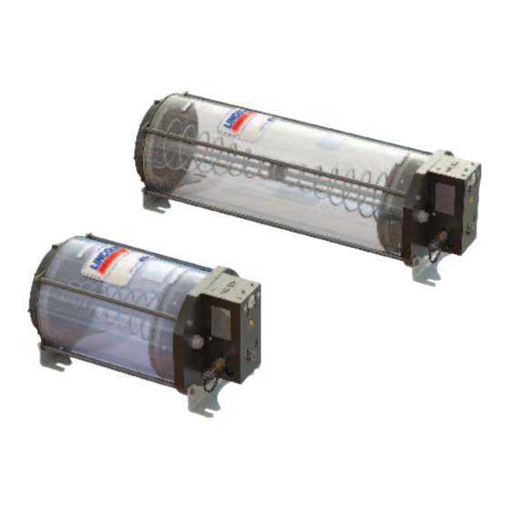
Hydraulically driven lubrication pump, with grease follower plate technology and ill level monitoring
Hide thumbs
Also See for HTL201:
- Installation instructions manual (56 pages) ,
- Assembly instructions manual (58 pages)

Subscribe to Our Youtube Channel
Related Manuals for SKF HTL201


Summary of Contents for SKF HTL201
- Page 1 Assembly instructions acc. to Hydraulically driven lubrication pump Machinery Directive 2006/42/EC HTL 201 with grease follower plate technology and ill level monitoring Version 01 951-171-044-EN...
-
Page 2: Ec Declaration Of Incorporation Acc. To Machinery Directive 2006/42/Ec, Appendix Ii Part 1 B
EC Declaration of Incorporation EC Declaration of Incorporation acc. to Machinery Directive 2006/42/EC, Appendix II Part 1 B The manufacturer, SKF Lubrication Systems Germany GmbH, Walldorf Plant, Heinrich-Hertz-Str. 2-8, DE - 69190 Walldorf, hereby declares conformity of the machine Designation:... -
Page 3: Masthead
Manufacturer Training Disclaimer of liability SKF Lubrication Systems Germany GmbH Address of manufacturer plants SKF conducts detailed training in order to The manufacturer shall not be held liable for Headquarters enable the maximum safety and efficiency. damage resulting from: ○ Improper usage, assembly,... -
Page 4: Table Of Contents
Emergency shutdown ................13 6.2.1 Minimum mounting dimensions ............25 1.18 Transport, assembly, maintenance, malfunction, 6.2.2 Assembly of the HTL201 ..............25 repair, shutdown, disposal ..............13 Connecting hydraulic lines (P) (T)............27 1.19 First start-up, daily start-up ...............15 Connecting a lubrication line ..............28 1.20... - Page 5 Replacing the reservoir assembly ............44 Emergency lubrication .................35 12.3 Replacing the pump body ..............46 6.10 Type identification code for the HTL201 pump .........36 Shutdown, disposal ..............48 First start-up ................37 13.1 Temporary shutdown ................48 Inspections before first start-up ............37 13.2...
-
Page 6: Explanation Of Symbols, Signs, And Abbreviations
Explanation of symbols, signs, and abbreviations Explanation of symbols, signs, and abbreviations These symbols can be used in the instructions. Symbols within safety instructions indicate the type and source of the hazard. General warning Risk of electrical shock Risk of slipping Hot surfaces Being drawn into machinery Crushing hazard... - Page 7 Explanation of symbols, signs, and abbreviations Abbreviations and conversion factors regarding °C degrees Celsius °F degrees Fahrenheit approx. approximately Kelvin ounce i.e. that is Newton fl. oz. Fluid ounce etc. et cetera hour inch incl. including second pound per square inch min.
-
Page 8: Safety Instructions
1. Safety instructions 1. Safety instructions 1.1 General safety instructions ○ Unauthorized persons must be kept tory regulations for accident prevention ○ The operator must ensure that the in- and environmental protection must be away. structions are read by all persons tasked observed. -
Page 9: Intended Use
1. Safety instructions 1.3 Intended use ○ Any malfunctions that occur must be ○ Use in areas with damaging radiation Feed lubricants only in compliance with the resolved according to responsibility. The specifications, technical data, and limits pre- (e.g., ionizing radiation) supervisor must be notified immediately sented in this manual. -
Page 10: Varnishing
1. Safety instructions 1.5 Varnishing 1.7 Prohibition of certain activities 1.9 Referenced documents The painting of all plastic components and The following activities must be performed In addition to this manual, the following seals of the products described here is pro- only by employees of the manufacturer or documents must be observed by the respec- hibited. -
Page 11: Markings On The Product
Model: ________________________________ Order No. 810-55325-1 P. No. ________________________________ Reservoir fill level MINimum S. No. ________________________________ indicator Order No. 810-55118-1 SKF Lubrication Systems Germany GmbH Reservoir fill level MAXimum indicator HTL201-XXXXX-X Model: XXX-XXXXX-X P. No.: Order No. 810-55117-1 XXXXXXXXXXXXXXXX S. -
Page 12: Authorized Persons
1. Safety instructions 1.13.2 Qualiied mechanic 1.12 Note on CE marking The CE marking is based on the require- Note on Pressure Equipment Directive A person with appropriate technical train- ments of the applied Directives: 2014/68/EU ing, knowledge, and experience who can recognize and avoid hazards that may occur ○... -
Page 13: Provision Of Personal Protective Gear
1. Safety instructions 1.15 Provision of personal protective gear 1.17 Emergency shutdown 1.18 Transport, assembly, maintenance, malfunction, repair, shutdown, disposal The operator must provide personal protec- Shut down the product in an emergency by: tive gear appropriate for the location and ○... - Page 14 1. Safety instructions ○ Transport only with suitable transport ○ All components used must be designed vehicle must not be damaged or their and lifting gear on marked paths. function impaired by the installation. for: - The maximum operating pressure ○...
-
Page 15: First Start-Up, Daily Start-Up
1. Safety instructions 1.19 First start-up, daily start-up 1.20 Cleaning ○ Use suitable hoisting equipment when ○ There is a fire hazard from the use of Ensure that: working with heavy parts. flammable cleaning agents. Use only ○ All safety mechanisms are fully present non-flammable cleaning agents that are ○... -
Page 16: Residual Risks In General
1. Safety instructions 1.21 Residual risks in general Residual risk Possible in lifecycle Remedy Unauthorized persons must be kept away. Personal injury, property damage due A B C G H K Nobody is allowed to be present below hoisted parts. to falling of hoisted parts Lift parts using suitable lifting gear. -
Page 17: Lubricants
○ Durability (physical/chemical stability) system. Ensure filling without introducing tion of suitable components for feeding the air! In case of error, bleed the HTL201. selected lubricant and in the planning and ○ Compatible with as many materials as design of a centralized lubrication system. -
Page 18: Material Compatibility
It is possible for lubricants to be tested in the company's laboratory for their suitability for pumping in centralized lubrication systems (e.g., "bleeding"). Please contact SKF if you have further ques- tions regarding lubricants. An overview of the lubricants we have tested is available on request. -
Page 19: Overview, Functional Description
Grease follower plate and tension spring Screw cap (see note on Fig. 2!) Fill connection with filler coupling Used to fill the HTL 201 Bleed screw (2x) Used to bleed the lubricant reservoir and the HTL201 pump CAUTION! Throttle (hidden) Screw cap is held under The throttle is protected by a cover screw. - Page 20 3. Overview, functional description Item Description see page Overview, Fig. 3 Bracket with assembly holes The pump is secured to the two brackets with assembly holes (4 bores). Pressure port P (G1/4) Is used to connect the supply line of the main machine's hydraulic system.
-
Page 21: Technical Data
Return flow port T G 1/4 tem. Ensure filling without introducing Lubrication line G 1/4 air! In case of error, bleed the HTL201. Nominal volume of lubricant reservoir 8 liters / 17 liters Filling Via fill connection Number of pump elements (outlets) Sound pressure level <... -
Page 22: Nominal Delivery Rates
4. Technical data 4.2 Nominal delivery rates Pump element C7 or K7 Nominal delivery rate per stroke 0.22 cm This information applies to NLGI Grade 2 greases at + 40 °C and 100 bar back pressure and the hydraulic operating pressure indicated in the diagram. Delivery rates can be increased or reduced by turning the throttle in the plus or minus direction, respectively. -
Page 23: Tightening Torques
4. Technical data 4.3 Tightening torques -See Figure 4 Overview, Fig. 4 Observe the specified tightening torques. Item Component Tightening torque: Pump element with integrated check valve 25 Nm ± 2.0 Nm Emergency lubricant nipple 14 Nm ± 1.0 Nm Bleed screw 15 Nm ±... -
Page 24: Delivery, Returns, Storage
5. Delivery, returns, storage 5. Delivery, returns, storage 5.1 Delivery ○ Protected from nearby sources of heat The following must be marked on the pack- After receipt of the supply, it must be in- aging of return shipments: or cold spected for any shipping damage and for ○... -
Page 25: Assembly
6. Assembly 6. Assembly 6.2.2 Assembly of the HTL201 6.1 General information -See Figure 5 and Fig. 6 ○ Drill the assembly holes for mounting as The HTL 201 is secured by the customer specified in corresponding chapter for the... - Page 26 6. Assembly Assembly drawing HTL201 with 8- and 17-liter lubricant reservoirs, Fig. 5 ØD View A View B 10,4 206,5 Reservoir dimensions [mm] 8 kg 17kg Minimum mounting dimensions 8 kg 17kg 10.4 Mounting diagram øD 951-171-044-EN - 26 -...
-
Page 27: Connecting Hydraulic Lines (P) (T)
6. Assembly 6.3 Connecting hydraulic lines (P) (T) -See Figure 7 Connecting hydraulic lines and the lubrication line, Fig. 7 Use suitable hydraulic screw unions and lines to connect the pump with the pressure port (P) and the return flow port (T) to the hydraulic circuit of the main machine / the carrier system. -
Page 28: Connecting A Lubrication Line
6. Assembly 6.4 Connecting a lubrication line -See Figure 7 ○ The delivery volume and the lubricant to be placed at the end of the main lubricant be fed line. CAUTION ○ The flow of lubricant should not be Risk of slipping Exercise caution when handling impeded by the incorporation of sharp Observe the following assembly informa-... -
Page 29: Connecting The Lubricant Level Switch
Quasi-analog lu- Supply Fill level analog signal analog signal range from 4 to 20 mA. SKF bricant level switch Pin 1 and pin 2 recommends that the customer evaluate the lubricant level switch to monitor lubricant 24VDC feeding. -
Page 30: Initial Filling
• Open alternative fill connections (12) (2x). To avoid possible air inclusions when ) During the subsequent filling process, do filling, SKF recommends switching on the HTL201 during the filling not exceed the MAXimum lubricant mark. process. 951-171-044-EN - 30 -... -
Page 31: Recharging
• If necessary, bleed the pump as described • If necessary, bleed the pump as described in Chapter 6.7. in Chapter 6.7. • Clean all lubricant residue from the • Clean all lubricant residue from the HTL201. HTL201. Optional Transfer pump - 31 - 951-171-044-EN... -
Page 32: Procedure When Overfilled
6. Assembly 6.6.4 Procedure when overilled -see Figure 2 and Fig. 9 • Run the HTL201 pump until the grease • Remove lubricant above the grease follower plate reaches the MINimum follower plate and clean the spring CAUTION mark. assembly. -
Page 33: Bleeding The Htl201
HTL201. filling.” In case of functional impairment (reduced delivery rate), bleed the pump as follows: Bleeding the HTL201, Fig. 10 • Switch off the hydraulic system on the main machine. • Place an oil or grease receiver tank under the HTL201. -
Page 34: Setting The Delivery Rate
6. Assembly 6.8 Setting the delivery rate • To adjust the delivery rate, turn the • Re-install the plug screw (1). -See Figure 11 throttle (3) in or out by the corresponding number of notch positions. Plug screw tightening torque The delivery rate cannot be 1 Nm ±... -
Page 35: Emergency Lubrication
6. Assembly 6.9 Emergency lubrication -See Figure 12 Emergency lubrication nipple of the HTL201, Fig. 12 • Place the transfer pump (1) with match- ing mating part on the emergency lubri- cation nipple (2). • Switch on the transfer pump and per-... -
Page 36: Type Identification Code For The Htl201 Pump
6. Assembly 6.10 Type identiication code for the HTL201 pump Example: 0 1 - K7 - 17.0 X M F K - SV120 Hydraulic Tool Lubrication Design 2 Application 0 Number of pump elements = 1 element Pump elements, piston diameter 7 mm... -
Page 37: First Start-Up
7. First start-up 7. First start-up To ensure safety and functionality, the person specified by the operator is required to perform the following inspections. Any detected deficiencies must be resolved immediately. The correction of deficiencies must be done exclusively by a specialist competent and authorized to do so. -
Page 38: Operation
8. Operation 8. Operation SKF products operate largely automatically. The activities required during normal op- eration are limited primarily to: ○ Initial filling with lubricant -See Chapter 6.6.1 ○ Adjusting the delivery rate -See Chapter 6.8 ○ Recharging with lubricant -See Chapter 6.6.2... -
Page 39: Cleaning
9. Cleaning 9. Cleaning WARNING Use steam-jet equipment or high-pressure cleaners only in accordance with the IP protection class of the main machine. Otherwise, electrical components such as the lubricant level switch may be damaged. Perform cleaning work only on products that have been de-energized and depressurized. Do not touch cables or electrical compo- nents with wet or moist hands. -
Page 40: Maintenance
10. Maintenance Maintenance Careful and regular maintenance is required in order to detect and remedy possibly malfunctions in time. The specific intervals must always be determined by the operator according to the operating conditions and regularly reviewed and adapted where necessary. If necessary, copy the table for regular maintenance activities. Maintenance checklist Activity to be performed Mechanical connection established correctly... -
Page 41: Cleaning / Replacing The Oil Strainer
(P). • Place an oil or grease receiver tank under • Switch the hydraulic system on the the HTL201. main machine on again. • Depressurize the supply line to the hy- draulic port (P). • Remove the screw union of the hydraulic port (P). -
Page 42: Malfunctions, Causes, And Remedies
11. Malfunctions Malfunctions, causes, and remedies Malfunctions table 1 Malfunction Possible cause Remedy ○ Carrier device's hydraulic system switched off • Switch on the hydraulic system. ○ Pressure in the hydraulic system is too low (< 80 bar) • Check the hydraulic system ○... -
Page 43: Repairs
(1) into the pump body. sure relief valve may necessitate repairs: removal of the HTL201 from its installation surface. Torque = 8 Nm + 1.0 Nm ○ Unauthorized persons must be kept away. -
Page 44: Replacing The Reservoir Assembly
(7). • Evenly tighten the fixing screws (15) crosswise with a torque of • Open one of the alternative fill connec- • Place the HTL201 on a clean surface. 15 Nm ± 1.0 tions (12). • Loosen and remove the pump/lubricant •... - Page 45 • Connect the power lead of the lubricant level switch (3.2) to the lubricant level switch. • Fill the HTL201 in accordance with Chap- ter 6.6.1 - “Initial filling.” • If necessary, bleed the HTL201 as de- scribed in Chapter 6.7.
-
Page 46: Replacing The Pump Body
• Grease the existing sealing ring (17) of the lubricant reservoir (3) and insert it in • Open one of the alternative fill connec- • Place the HTL201 on a clean surface. the groove in the reservoir bottom. tions (12). - Page 47 12. Repairs • Evenly tighten the fixing screws (15) • If necessary, bleed the HTL201 as de- crosswise with a torque of 15 Nm ± 1.0 scribed in Chapter 6.7. • Secure the HTL201 at the location against falling. Replacing the pump body, Fig. 16 •...
-
Page 48: Shutdown, Disposal
13. Shutdown, disposal Shutdown, disposal 13.1 Temporary shutdown 13.3 Disposal Temporary shutdown is performed by: Dispose of or recycle electrical Countries within the European Union components in accordance with ○ Switching off the main machine Waste should be avoided or minimized to WEEE Directive 2012/19/EU. -
Page 49: Spare Parts
14. Spare parts Spare parts Fig. 17 Designation Pcs. Item number Pressure relief valve, 270 bar 235-14343-2 Pressure relief valve, 120 bar 235-14343-5 Designation Pcs. Item number Fig. 18 Oil strainer screw G x 17, 100 μm 447-72394-1 Designation Pcs. Item number Fig. - Page 50 14. Spare parts Fig. 20 Designation Pcs. Item number Emergency lubricant nipple 251-14073-9 Fig. 21 Designation Pcs. Item number Filler coupling 995-000-705 Fig. 22 Designation Pcs. Item number Reservoir assembly for 8-liter lubricant reservoir 542-60473-1 Reservoir assembly for 17-liter lubricant reservoir 542-60474-1 951-171-044-EN - 50 -...
- Page 51 14. Spare parts Fig. 23 Designation Pcs. Item number Pump body, complete, for K7 pump element and 120 bar 642-41380-1 pressure relief valve Pump body, complete, for K7 pump element and 270 bar 642-41380-2 pressure relief valve Cable sockets M12x1, 4-pin design, without LED Designation Order No.
- Page 52 Lubrication Seals units Over the course of more than a century, SKF has specialized in five fields of competence and acquired a systems wide range of application expertise. We utilize this experience to provide innovative solutions to OEMs and other manufacturers in practically all industrial sectors worldwide.
Need help?
Do you have a question about the HTL201 and is the answer not in the manual?
Questions and answers