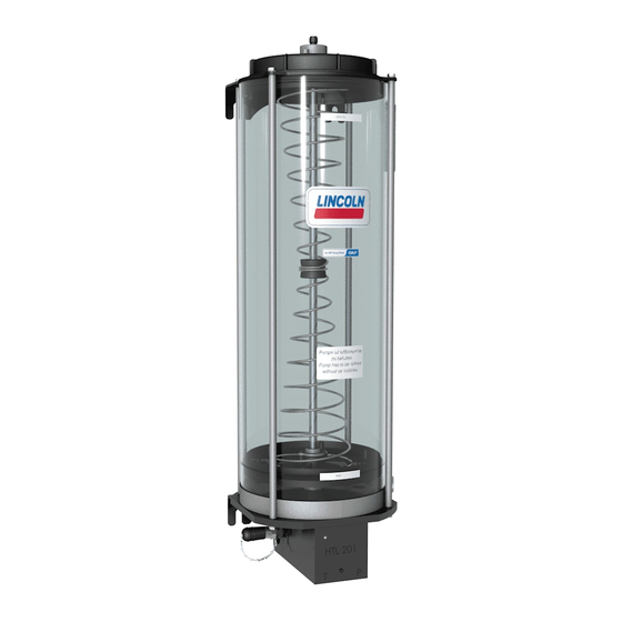
SKF Lincoln HTL201 Assembly Instructions Manual
Hydraulically driven lubrication pump with grease follower plate technology and fill level monitoring
Hide thumbs
Also See for Lincoln HTL201:
- Assembly instructions manual (52 pages) ,
- Installation instructions manual (56 pages)

Subscribe to Our Youtube Channel
Related Manuals for SKF Lincoln HTL201


Summary of Contents for SKF Lincoln HTL201
- Page 1 Assembly instructions Hydraulically driven lubrication pump acc. to Machinery Directive 2006/42/EC HTL201 with grease follower plate technology and fill level monitoring Version 03 951-171-044-EN...
-
Page 2: Ec Declaration Of Incorporation Acc. To Machinery Directive 2006/42/Ec, Appendix Ii Part 1 B
EC Declaration of Incorporation EC Declaration of Incorporation acc. to Machinery Directive 2006/42/EC, Appendix II Part 1 B The manufacturer, SKF Lubrication Systems Germany GmbH, Walldorf Plant, Heinrich-Hertz-Str. 2-8, DE - 69190 Walldorf, hereby declares conformity of the machinery Designation:... -
Page 3: Masthead
Manufacturer Training Disclaimer of liability SKF Lubrication Systems Germany GmbH Address of manufacturer plants SKF conducts detailed training in order to The manufacturer shall not be held liable for Headquarters enable the maximum safety and efficiency. damage resulting from: ○ Improper usage, assembly, operation,... -
Page 4: Table Of Contents
Table of contents Table of contents EC Declaration of Incorporation acc. to Machinery Directive 2006/42/EC, Appendix II Part 1 B ..................2 Masthead .....................3 Explanation of symbols, signs, and abbreviations ........6 Lubricants ................... 17 Safety instructions .................8 General information ................17 General safety instructions ..............8 Selection of lubricants ................17 General behavior when handling the product ........ - Page 5 Table of contents Maintenance ................41 6.6.1 Initial filling ....................30 10.1 Cleaning/replacing the oil strainer ............42 Filling with lubricant ................30 6.6.2 Refilling ....................32 Malfunctions, causes, and remedies ........... 43 6.6.3 Refill when the level drops below the MINimum mark ....32 6.6.4 Procedure with overfilling ..............33 Repairs ..................
-
Page 6: Explanation Of Symbols, Signs, And Abbreviations
Explanation of symbols, signs, and abbreviations Explanation of symbols, signs, and abbreviations These symbols may be used in the instructions. Symbols within safety instructions indicate the nature and source of the hazard. General warning Risk of electrical shock Risk of slipping Hot surfaces Being drawn into machinery Crushing hazard... - Page 7 Explanation of symbols, signs, and abbreviations Abbreviations and conversion factors regarding °C degrees Celsius °F degrees Fahrenheit approx. approximately Kelvin ounce i.e. that is Newton fl. oz. Fluid ounce etc. et cetera hour inch poss. possibly second pound per square inch if necessary if necessary sq.in.
-
Page 8: Safety Instructions
1. Safety instructions 1. Safety instructions 1.1 General safety instructions ○ Unauthorized persons must be kept tory regulations for accident prevention ○ The operator must ensure that the in- and environmental protection must be away. structions are read by all persons tasked observed. -
Page 9: Intended Use
1. Safety instructions 1.3 Intended use ○ Any malfunctions that occur must be ○ Use in areas with aggressive, corrosive Feed lubricants only in compliance with the resolved according to responsibility. The specifications, technical data, and limits pre- substances (e.g., high ozone loads) supervisor must be notified immediately sented in this manual. -
Page 10: Painting
1. Safety instructions 1.5 Painting 1.7 Prohibition of certain activities 1.9 Referenced documents The painting of all plastic components and The following activities must be performed In addition to this manual, the following seals of the products described here is pro- only by employees of the manufacturer or documents must be observed by the respec- hibited. -
Page 11: Markings On The Product
Order No. 810-55325-1 P. No. ________________________________ MINimum reservoir filling display S. No. ________________________________ Order No. 810-55118-1 MAXimum reservoir filling display Order No. 810-55117-1 SKF Lubrication Systems Germany GmbH HTL201-XXXXX-X Model: XXX-XXXXX-X P. No.: XXXXXXXXXXXXXXXX S. No.: XXX bar / X XXX psi... -
Page 12: Note On Ce Marking
1. Safety instructions 1.13.2 Qualified mechanic 1.12 Note on CE marking The CE marking is based on the require- Note on Pressure Equipment Directive A person with appropriate technical train- ments of the applied Directives: 2014/68/EU ing, knowledge, and experience who can recognize and avoid hazards that may occur ○... -
Page 13: Provision Of Personal Protective Gear
1. Safety instructions 1.15 Provision of personal protective gear 1.17 Emergency shutdown 1.18 Transport, assembly, maintenance, malfunction, repair, shutdown, disposal The operator must provide personal protec- Shut down the product in an emergency by: tive gear appropriate for the location and ○... - Page 14 1. Safety instructions ○ Maintenance and repair work can be ○ Dry any wet, slippery surfaces or cover - The maximum/minimum ambient tem- subject to restrictions at low or high appropriately. perature temperatures (e.g., alteration in the flow - The lubricant to be delivered ○...
-
Page 15: First Start-Up, Daily Start-Up
1. Safety instructions 1.19 First start-up, daily start-up 1.20 Cleaning ○ Avoid mixing up/incorrectly assembling ○ There is a fire hazard from the use of Ensure that: disassembled parts. Label parts. flammable cleaning agents. Use only ○ All safety mechanisms are fully present non-flammable cleaning agents that are and functional suitable for the intended purpose. -
Page 16: Residual Risks In General
1. Safety instructions 1.21 Residual risks in general Residual risk Possible in lifecycle Remedy Unauthorized persons must be kept away. Personal injury / property damage due A B C G H K Nobody is allowed to be present below hoisted parts. to falling of hoisted parts Lift parts using suitable lifting gear. -
Page 17: Lubricants
Large-sized air bubbles could cause a ○ Compatible with as many materials as and design of a centralized lubrication breakdown of the feed. SKF recommends possible system. electrical monitoring of the system for this reason. -
Page 18: Material Compatibility
It is possible for lubricants to be tested in the company's laboratory for their pumpability in centralized lubrication systems (e.g., "bleeding"). Please contact SKF if you have further ques- tions regarding lubricants. An overview of the lubricants we have tested is available on request. -
Page 19: Overview, Functional Description
3. Overview, functional description 3. Overview, functional description - See Figure 2 and Fig. 3 Item Description see page Overview, Fig. 2 Pump body 25/26 The pump body contains the pump element and the hy- draulic drive and conveying equipment. Mounting screws (pump/reservoir) (4x M8) Pump element 22/33... - Page 20 3. Overview, functional description Item Description see page Overview, Fig. 3 Holder with assembly holes The pump is secured at the two holders with assembly holes (4 bore holes) Pressure port P (G1/4) Used to connect the supply line of the hydraulic system of the main machine.
-
Page 21: Technical Data
Large-sized air bubbles could cause a min. 80 bar / max. 210 bar system breakdown of the feed. SKF recom- Working viscosity of the hydraulic oil for operating temperatures ≥ 20 – 1 000 mm mends electrical monitoring of the sys-... -
Page 22: Nominal Delivery Rates
4. Technical data 4.2 Nominal delivery rates Pump element C7 or K7 Nominal delivery rate per stroke 0,22 cm The specifications apply for Class NLGI 2 greases at + 40 °C, 100 bar back pressure and the hydraulic operating pressure specified in the diagram. The throttle can be turned in Plus or Minus direction to increase or decrease the delivery rates accordingly. -
Page 23: Tightening Torques
4. Technical data 4.3 Tightening torques - See Figure 4 Overview, Fig. 4 Observe the specified torques. Itnm Componnnt Torqun Pump element with integrated check valve 25 Nm ± 2.0 Nm Emergency lubrication nipple 14 Nm ± 1.0 Nm Vent plug 15 Nm ±... -
Page 24: Delivery, Returns, Storage
5. Delivery, returns, storage 5. Delivery, returns, storage 5.1 Delivery ○ Protected from nearby sources of heat The following must be marked on the pack- After receipt of the delivery, it must be in- aging of return shipments: or cold spected for any shipping damage and for ○... -
Page 25: Assembly
6. Assembly 6. Assembly 6.2.2 Assembling the HTL201 6.1 General information - See Figure 5 and Fig. 6 ○ The assembly holes for mounting are to The HTL201 is mounted at the customer site be drilled in accordance with specifica- by means of two holders, each of which is Only qualified technical personnel may in- tions in the corresponding chapter for the... - Page 26 6. Assembly HTL201 assembly drawing with 8-liter and 17-liter lubricant reservoir, Fig. 5 ØD View A View B 10,4 Rnsnrvoir dimnnsions [mm] 8 kg 17 kg 206,5 Minimum mounting 8 kg 17 kg dimnnsions 10.4 Mounting diagram øD - 26 - 951-171-044-EN Version 03...
-
Page 27: Connect Hydraulic Lines (P) (T)
6. Assembly 6.3 Connect hydraulic lines (P) (T) - See Figure 6 Connect hydraulic lines and lubrication line Fig. 6 Connect the pump with suitable hydraulic screw unions and hydraulic lines with the pressure port (P) and the return flow con- nection (T) on the hydraulic circuit of the main machine / of the carrier system. -
Page 28: Connecting A Lubrication Line
6. Assembly 6.4 Connecting a lubrication line - See Figure 6 ○ The delivery volume and the lubricant to ranged below the main lubricant line, be fed they should not be placed at the end of CAUTION the main lubricant line. Risk of slipping ○... -
Page 29: Connect The Fill Level Switch
Supply signal levels which are divided up across the Fill level analog signal Quasi-analog fill analog signal range of 4 to 20 mA. SKF rec- Pin 1 and Pin 2 level switch ommends a customer-supplied evaluation of the lubricant level signal for the purpose 24VDC of monitoring the lubricant feeding. -
Page 30: Initial Filling
- See Figure 8 same time keeping the screw cap (7) without introducing bubbles. closed SKF recommends that the initial filling be To avoid possible air inclusions when carried out with the HTL201 in horizontal • Switch on the transfer pump, start the filling, SKF recommends switching position. - Page 31 6. Assembly Check the packing rings of the two Initial filling Fig. 8 vent plugs for damage, replacing them if necessary (see Chapter 14). • Screw the two vent plugs (5) into the vent boreholes (6) and tighten them 15 ± 0.1 Nm) •...
-
Page 32: Refilling
6. Assembly 6.6.3 Refill when the level drops below • Clean the HTL201 completely of lubri- the MINimum mark cant residue • Resume the filling process until the sec- • For the procedure - See Chapter 6.6.1, ond ventilation hose can also be removed possibly Chapter 12.4. -
Page 33: Procedure With Overfilling
6. Assembly 6.6.4 Procedure with overfilling - See Figure 2 and Fig. 9 • Allow the HTL201 pump to continue • Remove lubricant above the grease fol- running until the grease follower plate lower plate, clean the spring assembly CAUTION has reached the MINimum mark Take care to ensure the following Risk of injury! -
Page 34: Bleeding The Htl201
6. Assembly 6.7 Bleeding the HTL201 - See Figure 10 Check the packing rings of the vent • Tighten the vent plug (2). If air inclusions are visible in the lubricant plug for damage, replacing them if contained in the lubricant reservoir, then a necessary Tightening torque = 15 Nm ±... -
Page 35: Setting The Delivery Rate
6. Assembly 6.8 Setting the delivery rate - See Figure 11 • To set the delivery rate, turn the throttle • Reinstall the plug screw (1) (3) open or shut by the corresponding number of notch positions Tightening torque Plug screw 1 Nm ±... -
Page 36: Emergency Lubrication
6. Assembly 6.9 Emergency lubrication - See Figure 12 Emergency lubrication nipple of the HTL201, Fig. 12 • Set the transfer pump (1) with matching counterpart on the emergency lubrica- tion nipple (2). • Switch on the transfer pump and carry out an emergency lubrication until the connected lubrication points are supplied with sufficient lubricant. -
Page 37: Type Identification Code Pump Htl201
6. Assembly 6.10 Type identification code Pump HTL201 Example: 0 1 - K7 - 17.0 X M K - SV120 Hydraulic Tool Lubrication Design 2 Application 0 Number of pump elements = 1 Element Pump element, piston diameter 7 mm Standard for grease = Increased fitting tolerance and oil... -
Page 38: First Start-Up
7. First start-up 7. First start-up To ensure safety and functionality, the person specified by the operator is required to conduct the following inspections. Any detected defi- ciencies must be resolved immediately. The correction of deficiencies must be done exclusively by a specialist competent and authorized to do so. -
Page 39: Operation
8. Operation 8. Operation SKF products operate largely automatically. Activities during normal operation are lim- ited essentially to: ○ Initial filling with lubricant - See Chapter 6.6.1 ○ Setting the delivery rate - See Chapter 6.8 ○ Refilling with lubricant - See Chapter 6.6.2... -
Page 40: Cleaning
9. Cleaning 9. Cleaning WARNING Use steam-jet equipment or high-pressure cleaners only in accordance with the IP protection class of the main machine. Otherwise, electrical components such as the fill level switch could become damaged. Perform cleaning work only on products that have been de-energized and depressurized. Do not touch cables or electrical compo- nents with wet or moist hands. -
Page 41: Maintenance
10. Maintenance Maintenance Careful and regular maintenance is required in order to detect and remedy possibly malfunctions in time. The specific intervals must always be determined by the operator according to the operating conditions and regularly reviewed and adapted where necessary. If necessary, copy the table for regular maintenance activities. Maintenance checklist Activity to be performed Mechanical connection established correctly... -
Page 42: Cleaning/Replacing The Oil Strainer
10. Maintenance 10.1 Cleaning/replacing the oil strainer - See Figure 13 The oil strainer must be cleaned • Open the supply feed to the hydraulic or replaced every 1000 hours of connection (P) operation. • Switch off the hydraulic system of the Cleaning/replacing the oil strainer Fig. -
Page 43: Malfunctions, Causes, And Remedies
11. Malfunctions Malfunctions, causes, and remedies Malfunctions table 1 Malfunction Possible cause Remedy ○ Carrier device's hydraulic system switched off • Switch on the hydraulic system ○ Pressure in the hydraulic system is too low (< 80 bar) • Check the hydraulic system ○... -
Page 44: Repairs
12. Repairs Repairs 12.1 Replace the pressure relief valve WARNING - See Figure 14 • Lightly oil/grease the packing ring (2) of Risk of injury the new pressure relief valve In order to access the pressure At a minimum, the following safety •... -
Page 45: Change The Reservoir Assembly
12. Repairs 12.2 Change the reservoir assembly - See Figure 2, Fig. 3 and Fig. 15 • Disconnect the power lead of the fill level • Set the old lubricant reservoir (3) aside Reservoir assembly, switch (3.2), set the power lead aside - See spare parts list Chapter 14, Fig. - Page 46 12. Repairs Change the reservoir assembly Fig. 15 • Connect and tighten the pressure line (P) and return line (T) of the carrier system at the pump connection • Connect the lubricant line to the pump element (2) • Connect the power lead of the fill level switch (3.2) to the fill level switch •...
-
Page 47: Change The Pump Body
12. Repairs 12.3 Change the pump body - See Figure 2, Fig. 3 and Fig. 16 • Disconnect the power lead of the fill level • Open both vent plugs (5) Pump body, switch (3.2), set the power lead aside - See spare parts list Chapter 14, Fig. - Page 48 12. Repairs • Tighten the fastening screws (15) evenly • Fill the HTL201 up to the MAXimum • Bleed the HTL201 in accordance with crosswise with a tightening torque (15 mark Chapter 6.7 if necessary ± 1.0 • Secure the HTL201 against falling at the installation location Replace the pump body Fig.
-
Page 49: Insertion Of The Two Ventilation Hoses Into The Reservoir Assembly Of The Htl201 8 L /17 L
12. Repairs 12.4 Insertion of the two ventilation hoses into the reservoir assembly of the HTL201 8 l /17 l - See Figure 17 and Fig. 19 Insert ventilation hoses Fig. 17 The insertion of the two ventilation hoses is necessary after replacing a pump body in order to eliminate air inclusions inside the pump body and inside the reservoir as- sembly. - Page 50 12. Repairs • Completely empty the HTL201 8 l / 17 l • Tilt the follower plate (6) in the reservoir in Insert ventilation hoses Fig. 18 pump such a way that a gap is created between the reservoir front side (Lincoln plate on •...
- Page 51 12. Repairs approximately 10 mm underneath the • Insert the spring assembly (4) back into Insert ventilation hoses Fig. 19 follower plate (6)) the reservoir and align it on the follower plate (6) • Thread the other ends (10) of the venti- lation hoses (9) through the venting duct The spring assembly of the 17 l (11) of the reservoir and fasten them in...
-
Page 52: Shutdown, Disposal
13. Shutdown, disposal Shutdown, disposal 13.1 Temporary shutdown 13.3 Disposal Temporary shutdown is performed by: Dispose of or recycle electrical Countries within the European Union components in accordance with ○ Switching off the main machine Waste should be avoided or minimized to WEEE Directive 2012/19/EU. -
Page 53: Spare Parts
14. Spare parts Spare parts Fig. 20 Designation Pcs. Item number Pressure relief valve, 270 bar 235-14343-2 Pressure relief valve, 120 bar 235-14343-5 Fig. 21 Designation Pcs. Item number Oil strainer screw G x 17, 100 μm 447-72394-1 Fig. 22 Designation Pcs. - Page 54 14. Spare parts Fig. 23 Designation Pcs. Item number Emergency lubrication nipple 251-14073-9 Fig. 24 Designation Pcs. Item number Filler coupling 995-000-705 Fig. 25 Designation Pcs. Item number Reservoir assembly for 8-liter lubricant reservoir 542-60473-1 Reservoir assembly for 17-liter lubricant reservoir 542-60474-1 - 54 - 951-171-044-EN...
- Page 55 14. Spare parts Fig. 26 Designation Pcs. Item number Pump body assy. for K7 pump element and 120 bar pressure 642-41380-1 relief valve Pump body assy. for K7 pump element and 270 bar pressure 642-41380-2 relief valve Cable sockets M12x1, 4-pin design, without LED Designation Order No.
- Page 56 951-171-044-EN 19/11/2020 Version 03 SKF Lubrication Systems Germany GmbH Walldorf Plant Heinrich-Hertz-Str. 2-8 DE - 69190 Walldorf, Germany Tel: +49 (0) 6227 33-0 Fax: +49 (0) 6227 33-259 E-mail: Lubrication-germany@skf.com www.skf.com/lubrication...
- Page 58 EC Declaration of Incorporation acc. to Machinery Directive 2006/42/EC, Appendix II Part 1 B The manufacturer, SKF Lubrication Systems Germany GmbH, Walldorf Plant, Heinrich-Hertz-Str. 2-8, DE - 69190 Walldorf, hereby declares conformity of the machinery Designation: Hydraulically driven lubrication pump for the feeding of lubricants...
Need help?
Do you have a question about the Lincoln HTL201 and is the answer not in the manual?
Questions and answers