
Related Manuals for SKF Lincoln P205-M075 2K7-000 EEX Series


Summary of Contents for SKF Lincoln P205-M075 2K7-000 EEX Series
- Page 1 Operating Instructions Lubrication pump P205EEX following ATEX directive 2014/34/EU 951-181-014-EN Version 16 2021/07/12...
-
Page 2: Eu Declaration Of Conformity Following Atex Directive 2014/34/Eu
EU Declaration of conformity following ATEX directive 2014/34/EU, annex X The manufacturer, SKF Lubrication Systems Germany GmbH, Walldorf Facilities, Heinrich-Hertz-Str. 2-8, DE - 69190 Walldorf hereby declares under sole responsibility that the electrical equipment Designation: Electrically driven pump to supply lubricant within a centralized lubrication system... -
Page 3: Legal Notice
The manufacturer shall not be held respon- In order to provide a maximum of safety and www.skf.com/lubrication sible for damages caused by: economic viability, SKF carries out detailed ○ non appropriate use training courses. It is recommended that the Manufacturer's facilities faulty assembly, operation, setting, main- training courses are attended. -
Page 4: Table Of Contents
Table of contents Table of contents EU Declaration of conformity following ATEX directive 2014/34/EU ..2 Legal notice ....................3 Explanation of symbols, signs and abbreviations ........7 1.20 Cleaning ....................16 Safety instructions ................ 9 1.21 Safety-related protective and emergency devices must ....16 General safety instructions .............. - Page 5 Table of contents Overview of pump versions ..............32 Electrical connection of the low-level indication .......52 Technical data of motor variants ............34 Electrical connection of ELNOR motor ..........53 Reservoir versions ................42 Adjustment of the KR pump elements ..........55 Capacitive sensors ................43 Lubrication line connection..............56 Contact rod ....................45 6.10...
- Page 6 Table of contents Maintenance ................63 Annexes purchase parts ................83 10.1 Pump maintenance ................64 Declaration of conformity of gear make Rehfuss ........83 Maintenance of gear unit ..............65 10.2 Declaration of conformity of EDR motor make SEW ........ 84 10.3 Cleaning of capacitive sensors ............65 Declaration of conformity of DFR motor make SEW ........
-
Page 7: Explanation Of Symbols, Signs And Abbreviations
Explanation of symbols, signs and abbreviations Explanation of symbols, signs and abbreviations The following abbreviations may be used within these instructions. Symbols within safety notes mark the kind and source of the hazard. General warning Dangerous electrical voltage Risk of falling Hot surfaces Unintentional intake Crushing hazard... - Page 8 Explanation of symbols, signs and abbreviations Abbreviations and conversion factors regarding °C degrees Celsius °F degrees Fahrenheit approx. approximately Kelvin Ounce i.e. that is Newton fl. oz. fluid ounce etc. et cetera hour inch poss. possibly second pounds per square inch if appl.
-
Page 9: Safety Instructions
1. Safety instructions 1. Safety instructions 1.2 General behaviour when handling the 1.1 General safety instructions ○ Remedy occurring faults in the frame of product ○ The owner must ensure that safety infor- responsibilities. Immediately inform your ○ The product may be used only in aware- superior in the case of faults beyond your mation has been read by any persons en- ness of the potential dangers, in proper... -
Page 10: Intended Use
1. Safety instructions 1.3 Intended use ○ in areas with harmful radiation (e. g. ion- Supply of lubricants within a centralized ○ in explosive dust atmospheres, the mini- lubrication system following the specifica- ising radiation) mum ignition and glow temperature of tions, technical data and limits stated in which is smaller than 150 % of the maxi- ○... -
Page 11: Modifications Of The Product
1. Safety instructions 1.6 Modifications of the product 1.9 Other applicable documents 1.10 Markings on the product Unauthorized conversions or modifica- In addition to these instructions, the follow- tions may result in unforeseeable impacts ing documents must be observed by the Warning of dangerous electrical on safety. -
Page 12: Notes Related To The Type Identification Plate
1. Safety instructions 1.11 Notes related to the type identifica- Reference on Low Voltage Directive tion plate SKF Lubrication Systems Germany GmbH 2014/35/EU The type identification plate states im- Model: xxx -xxx-xxx-xxx-xxx The protective regulations of Low Voltage P. No.:... -
Page 13: Persons Authorized To Operate The Pump
1. Safety instructions 1.13 Persons authorized to operate the 1.13.4 Specialist for maintenance and 1.14 Briefing of external technicians pump repairs in potentially explosive Prior to commencing the activities, external atmospheres technicians must be informed by the opera- 1.13.1 Operator A person who is qualified by training, know- tor of the company safety provisions, the A person who is qualified by training, know-... -
Page 14: Operation
1. Safety instructions 1.16 Operation ○ Carry out transport using suitable trans- ○ Dry or cover wet, slippery surfaces The following must be observed during port and hoisting equipment on suitable accordingly. commissioning and operation: ways only. ○ Any information within this manual and ○... -
Page 15: Initial Commissioning, Daily Start-Up
Do not damage lines and ○ When working with heavy parts use suit- cables when drilling. Changes to SKF products are prohibited. This includes able lifting tools. all drilling, welding, flame-cutting, and ○ Avoid mixing up or wrong assembly grinding work. -
Page 16: Cleaning
1. Safety instructions 1.21 Safety-related protective and emer- 1.20 Cleaning gency devices must ○ Risk of fire and explosion when using ○ Safety-related protective and emergency inflammable cleaning agents Only use devices must not be removed, modified or non-flammable cleaning agents suitable affected otherwise in their function and are for the purpose. -
Page 17: Special Safety Instructions Regarding Explosion Protection
1. Safety instructions 1.22 Special safety instructions regarding explosion protection ○ Always behave so that explosion hazards ○ Check the machine at regular intervals ○ The filling-level monitoring must be en- are avoided. in line with the operating conditions for sured by the operator at a high degree of damage which may represent an ignition safety. - Page 18 1. Safety instructions ○ Only use tools and clothing which are ○ If transport lugs are dismantled after ○ Avoid dust accumulation and remove permitted for use in potentially explosive set-up, the threaded bores must be per- dust immediately. Dust accumulations areas (ESD).
-
Page 19: Expiry Of The Atex Approval
○ All information given in these instructions ○ Unauthorized modifications or stated in the referenced documents. ○ Use of non-original SKF spare parts ○ All laws and regulations to be complied ○ non-observance of these instructions with by the user. -
Page 20: Residual Risks
1. Safety instructions 1.26 Residual risks Residual risk Possible in life cycle Prevention/ remedy Personal injury/ material damage due to Keep unauthorized persons away. No people may remain under suspended A B C G H K falling of raised parts loads. -
Page 21: Residual Risks Atex
1. Safety instructions 1.27 Residual risks ATEX Residual risk Prevention/ remedy Usage in a potentially explosive atmos- phere without testing the equipoten- Check the equipotential bonding with regard to electrical continuity before the initial start-up, tial bonding with regard to electrical after each repair and additionally at regular intervals to be determined by the operator. - Page 22 1. Safety instructions Residual risk Prevention/ remedy Generation of electrostatic charges and sparks Secure parts against falling. Where appropriate, cover parts in order to avoid the for- C D E F G through dropping parts. mation of sparks. Bringing catalytic, unstable or pyrophoric sub- Ensure that none of these substances gets into the potentially explosive area.
-
Page 23: Lubricants
2.2 Selection of lubricants Lubricants are used specifically for certain Lubricants must generally be compatible SKF considers lubricants to be an element application purposes. In order to fulfil their with the following materials: of system design. A suitable lubricant is se- ○... -
Page 24: Ageing Of Lubricants
(e.g. "bleeding"). on the packaging have to be Please contact SKF. if you have further observed. questions regarding lubricants. You may request an overview of the lubri- cants tested by SKF. -
Page 25: Overview, Functional Description
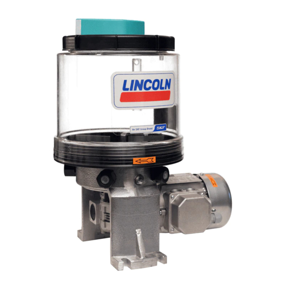
3. Overview, functional description 3. Overview, functional description Overview Fig. 1 1 Reservoir lid with earthing The terminal box, if any, for connection of the low-level indication is located on the reservoir lid. The reservoir lid is connected to the res- ervoir and the pump earthing system via an earth strap. - Page 26 3. Overview, functional description Overview Fig. 2 4 Pump housing The pump housing serves to fasten the pump to the base. Either pump elements or closure screws are screwed into the pump housing. 5 Gear The gear reduces the motor speed to the nec- essary speed of the pump.
- Page 27 3. Overview, functional description Overview Fig. 3 Operating principle: The gear (5) reduces the speed of the mo- tor (6) to the required speed of the pump's eccentric shaft. The eccentric shaft drives the pump elements (3) and the stirring paddle in the reservoir. The stirring paddle homogenizes and ven- tilates the lubricant and pushes it in the direction of the suction boreholes of the...
-
Page 28: Technical Data
4. Technical data 4. Technical data 4.1 Mechanical data Admissible operating pressure max. 350 bar Pump elements max. 5 Reservoir variants for grease Lubricating greases up to NLGI 2 Approved lubricant consistencies Reservoir variants for oil Lubrication oils of at least 40 mm2/s at operating temperature We recommend a use of lubricants with a high conductivity (>... -
Page 29: Electrics
4. Technical data 4.2 Electrics: Connection must be done in such way that a permanent, safe electrical connection can be maintained (use safe protective conductor connection and dedicated cable ends; avoid protruding wire ends). Make sure that there are no foreign particles, dirt or humidity in the terminal box. Close the terminal box dust- and watertight. -
Page 30: Nominal Output Volumes
4. Technical data Nominal output volumes Pump element Nominal output per pump element and stroke 0.16 cc 0.23 cc 0.04 - 0.18 cc The stated nominal outputs per stroke refer to NLGI II lubricating greases at an operating temperature of + 20 °C and a backpressure of 100 bar on the pump element. -
Page 31: Tightening Torques
4. Technical data 4.4 Tightening torques The stated tightening torques must be adhered to. Pump element with housing 25 Nm ± 2.5 Nm Pressure control valve 6 Nm ± 0.6 Nm Closure screw with housing 20 Nm ± 0.2 Nm Filling connection / return line 10 Nm ±... -
Page 32: Overview Of Pump Versions
4. Technical data 4.5 Overview of pump versions Ambient Part number Designation on the type identification plate Motor ReservoirSensor temperature range Explosion protection marking min. max. 655-41261-1 P205-M075- 5XL -1K6-400 EEX - 20 °C + 40 °C II 2G Ex h IIC T4 Gb II 2D Ex h IIIC T120°C Db 655-41261-2 P205-M075- 5XL -1K6-460 KAP. - Page 33 4. Technical data Ambient Part number Designation on the type identification plate Motor Reservoir Sensor temperature range Explosion protection marking min. max. Seawater-resistant version 655-46716-1 P205-M075-10XL -2K7/1KR-460 KAP. EEX - 20 °C + 50 °C II 3D Ex h IIIC T120°C Dc 655-46716-2 P205-M075- 5XL -1K6- 24 KAP.
-
Page 34: Technical Data Of Motor Variants
4. Technical data 4.6 Technical data of motor variants Assignment of the motor variants to a certain pump type, see table 4.5 Overview of pump variants Part number Type of motor Manufacturer 245-13998-5 EDFR63S4 Rated voltage V AC Operating mode Circuit Design Rated frequency Size... - Page 35 4. Technical data Part number Type of motor Manufacturer 245-13998-6 EDFR63S4 Rated voltage V AC Operating mode Circuit Design Rated frequency Size Rated power 0.12 0.12 Degree of protection Rated speed 1380 1380 Insulation class Nominal current 0.71 Flange Starting current 3.4 x rated current Shaft Ø...
- Page 36 4. Technical data Part number Type of motor Manufacturer 245-13998-8 EDFR63S4 Rated voltage V AC Operating mode Circuit Design Rated frequency Size Rated power 0.12 0.12 Degree of protection Rated speed 1380 1380 Insulation class F / B Nominal current 0.71 Flange Starting current 3.4 x rated current Shaft Ø...
- Page 37 4. Technical data Part number Type of motor Manufacturer 245-00101-3 EDFR63S4 Rated voltage V AC Operating mode Circuit Design Rated frequency Size Rated power 0.12 0.12 Degree of protection Rated speed 1680 1680 Insulation class Nominal current 0.59 0.34 Flange Starting current 4.0 x rated current Shaft Ø...
- Page 38 4. Technical data Part number Type of motor Manufacturer 245-13980-4 BA AP80SH AR ELNOR Rated voltage V DC Operating mode Design Size Rated power 0.09 Degree of protection Rated speed 1607 Insulation class Nominal current Flange Starting current 3.0 x rated current Shaft Ø...
- Page 39 4. Technical data Part number Type of motor Manufacturer 245-13975-4 KR/AC1204065B14M4 CEMP Rated voltage V AC Operating mode Design Rated frequency Size Rated power 0.09 Degree of protection Rated speed 1400 Insulation class Nominal current Flange Starting current 2.5 x rated current Shaft Ø...
- Page 40 4. Technical data Part number Type of motor Manufacturer 245-13975-7 KR/AC1204065B14M4 CEMP Rated voltage V AC Operating mode Design Rated frequency Size Rated power 0.09 Degree of protection Rated speed 1400 Insulation class Nominal current Flange Starting current 2.5 x rated current Shaft Ø...
- Page 41 4. Technical data Part number Type of motor Manufacturer 245-00107-4 EDFR63S4 Rated voltage 219-241 380-420 V AC Operating mode Design Rated frequency Size Rated power 0.12 0.12 Degree of protection Rated speed 1380 1380 Insulation class Nominal current 0.71 0.40 Flange Starting current 3.4 x rated current Shaft...
-
Page 42: Reservoir Versions
4. Technical data 4.7 Reservoir versions Assignment to a certain pump type, see table 4.5 Overview of pump variants 5 XL / 5 YL 5 XYN 5 XL 10 XL 10 XYN Part number Part number Part number Part number Part number 655-46805-2 655-46404-7... -
Page 43: Capacitive Sensors
4. Technical data 4.8 Capacitive sensors Assignment to a certain pump type, see table 4.1 Overview of pump variants Part numbers 664-34621-2 (aligned for grease) / 664-34621-5 (aligned for oil) D | part number 664-34621-3 (like 664-34621-2, but with 10 m connection cable) Rated operating distance Sn flush installation II 2G EX ia IIC T6 Gb... - Page 44 4. Technical data Part number 664-34621-7 (aligned for grease) Housing Stainless steel II 1G EX ia IIC T4/T5 Explosion protection marking Insulation material PEEK II 1D EX ta IIIC T 100 °C Da Ambient temperature -40 °C to + 85 °C Factory setting 0.1 s Operating temperature -40 °C to + 115 °C...
-
Page 45: Contact Rod
4. Technical data 4.9 Contact rod Part number 400-24085-1 Simple equipment without certification following EN 60079-x. Therefore no explosion protection marking. For connection to an intrinsically safe circuit with a maximum switching capacity of 100 mA and at least ignition protection category Ex Connection must be provided by a suitable isolating switching amplifier always. -
Page 46: Delivery, Returns, And Storage
6 - 12 months corresponding 5.2 Returns to the conditions at the place of storage. Clean all parts and pack them properly (i.e. SKF products are subject to the following We recommend: following the regulations of the recipient storage conditions: ○... -
Page 47: Special Storage Conditions For Parts Primed With Lubricant
5. Delivery, returns, and storage 5.4.3 Storage period exceeding 18 5.4 Special storage conditions for parts Metering device • Remove all connection lines and closure primed with lubricant months screws, if any. To avoid dysfunctions consult the manufac- The conditions mentioned in the following • Connect the pump primed with new turer before commissioning. -
Page 48: Installation
6. Installation 6. Installation 6.2 Place of installation 6.1 General information ○ Possibly existing visual monitoring de- Protect the product against humidity, dust Only qualified technical personnel may vices, e.g. pressure gauges, MIN/MAX and vibrations and install it in an easily ac- install the products described in these markings or piston detectors, must be cessible position to facilitate other installa-... -
Page 49: Mechanical Connection
6. Installation 6.3 Mechanical connection Minimum assembly dimensions Fig. 4 6.3.1 Minimum assembly dimensions Ensure sufficient space for maintenance or repair work or for assembly of further components of the centralized lubrication system by leaving a free space of at least 100 mm into each direction in addition to the stated dimensions. -
Page 50: Installation Bores
6. Installation 6.3.2 Installation bores Installation bores Fig. 5 NOTICE Damage to the pump Fastening may not be done on two parts moving against one another (machine bed and machine assembly). The product is fastened to the 4 mounting bores (7). Drill the mounting bores on non load-bearing parts only. -
Page 51: Electrical Connection Of Sew And Cemp Motors
6. Installation Electrical connection, Fig. 6 6.4 Electrical connection of SEW and CEMP motors WARNING Electric shock Make sure to disconnect the product from the power supply before carrying out any works on electrical components. WARNING Risk of explosion Connect the product to the equi- potential bonding of the superior machine. -
Page 52: Protective Conductor Connection Of Sew Motor
6. Installation Correct connection of the protective conductor in the terminal box Fig. 7 6.5 Protective conductor connection of SEW motor To connect the protective conductor in the terminal box (8) of the motor use a cable lug. The cable lug and the motor housing must be separated by means of a washer (9). -
Page 53: Electrical Connection Of Elnor Motor
6. Installation Electrical connection, Fig. 8 6.7 Electrical connection of ELNOR For electrical connection proceed as motor follows: • Loosen the 3 screws (1) and remove WARNING the lid. Explosion hazard • Unscrew the terminal insert (2a) of the Loss of pressure-resistant cable gland (2) to that extent that about encapsulation 7 threads (3) will become visible. - Page 54 6. Installation Correct connection in the terminal box Fig. 9 NOTICE Damage to the motor Risk of damage to the motor Always connect the thermal circuit breaker to the control circuit of the motor. • Screw-in terminal insert (2a) by hand until cable is clamped safely (higher resistance can be felt).
-
Page 55: Adjustment Of The Kr Pump Elements
6. Installation 6.8 Adjustment of the KR pump elements Adjusting pump element KR Fig. 10 lower output volume CAUTION Risk of falling higher output volume Exercise care when dealing with lubricants. Immediately absorb and remove and leaked lubricant. 0,18 0,16 Output adjustment of the KR 0,14 pump elements is possible only... -
Page 56: Lubrication Line Connection
6. Installation 6.9 Lubrication line connection ○ The lubricant flow should not be impeded Observe the following installation instruc- tions for safe and smooth operation. by the installation of sharp elbows, angle CAUTION ○ Use clean components and primed lubri- valves, gaskets protruding to the inside, Risk of falling or cross-section changes (big to small). -
Page 57: Filling With Lubricant
6. Installation Manual filling: 6.10 Filling with lubricant 6.10.1 Filling via the reservoir lid • Connect filling pump to filling adapter. • Open the reservoir lid. WARNING WARNING • Switch the filling pump on. Hand injuries caused by the Risk of explosion • Fill in lubricant up to a maximum of 1 cm The ignition temperature of the stirring paddle... -
Page 58: Inadvertent Filling With Incorrect Lubricant
6. Installation 6.10.3 Inadvertent filling with incorrect lubricant Should incorrect lubricant have been filled, please proceed as follows: • Switch off the pump and secure it • Switch off the pump and secure it against against being switched on. being switched on. • Remove the lubricant from the • Reconnect the lubricant lines reservoir. -
Page 59: Initial Start-Up
7. Initial start-up 7. Initial start-up In order to warrant safety and function, a person assigned by the operator must carry out the following inspections. Remedy detected de- fects before the initial start-up. Deficiencies may be remedied by an authorized and qualified specialist only. Checklist - Inspections prior to the initial start-up 7.1 Inspections prior to initial start-up Electrics... -
Page 60: Inspections During Initial Start-Up
7. Initial start-up Check list - Inspections during the initial start-up 7.2 Inspections during initial start-up No unusual noises, vibrations, accumulation of moisture, or odours present No smoke or smouldering spots No unwanted escape of lubricant from connections (leakages). Lubricant is supplied free from bubbles Bearings and friction points are provided with the planned amount of lubricant - 60 - 951-181-014-EN... -
Page 61: Operation
8. Operation 8. Operation SKF products operate automatically to the greatest possible extent. Basically, activities during standard opera- tion are limited to the control of the filling level and the timely refilling of lubricant as well as the outside cleaning of the product in case of contamination. -
Page 62: Cleaning
To do so, contact the Thoroughly remove residues • Mark and secure wet areas. SKF Customer Service. of cleaning agents from the • Keep unauthorized persons away. product and rinse off with clear 9.4 Cleaning of capacitive sensors • Thorough cleaning of all outer surfaces... -
Page 63: Maintenance
10. Maintenance Maintenance Regular and appropriate maintenance is WARNING a prerequisite to detect and clear faults in time. As it is not possible for us to exactly Risk of explosion define the operating conditions, we cannot Inspection and maintenance of indicate any definite deadlines. -
Page 64: Pump Maintenance
10. Maintenance 10.1 Pump maintenance Checklist pump maintenance Activity to be done Electrical connection carried out correctly Mechanical connection carried out correctly The performance data of the previously indicated connections correspond to the specifications stated in the Technical data All components, such as lubrication lines and metering devices, have been correctly installed Product protected with adequate pressure relief valve No visible damage, contamination and corrosion Any dismantled protection and monitoring equipment has been reassembled and checked for correct function... -
Page 65: Maintenance Of Gear Unit
10. Maintenance 10.2 Maintenance of gear unit Activity to be done Interval / deadline Visual check for leakages Every 3,000 hours, but at least once a year Visual check for damage of the surface protec- Depending on the type of application and ambi- tion/ corrosion protection ent conditions For further relevant information on maintenance, see original Instructions by the gear... -
Page 66: Motor Maintenance
10. Maintenance 10.4 Motor maintenance Maintenance check list of SEW and CEMP motors CEMP Activity to be done Interval / deadline Interval / deadline Every 4 weeks Every 4 weeks Inspection of the cooling air ways of the motor with Depending on the local contamination load Depending on the local contamination load regard to contamination... - Page 67 10. Maintenance Checklist maintenance of ELNOR motors Activity to be done Interval / deadline Interval depends on the operating conditions, at the latest, however, every Check the current and earth cables for damages and proper installation 4 weeks First inspection Every 500 operating hours or every 6 months Once a year: ○...
-
Page 68: Measurement Of The Insulation Resistance
10. Maintenance 10.5 Measurement of the insulation resis- tance WARNING Electric shock Do not touch the terminals when measuring the insulation resist- ance. Wear insulating gloves. Ob- serve the manual of the insulation measurement device. NOTICE Risk of damage to the motor The voltage applied for the insulation test must not exceed 500 V. -
Page 69: Troubleshooting
11. Troubleshooting Troubleshooting 11.1 Fault table of pump Fault Possible cause Remedy No supply Reservoir empty Check visually, refill if necessary. Air bubbles in the lubricant Vent Suction bore of pump element is clogged. Disassemble and clean the pump elements. Inappropriate lubricant Check and, if necessary, use a different type of lubricant. - Page 70 11. Troubleshooting 11.2 Fault table of the Rehfuss gear Fault Possible cause Remedy Check oil and oil level, if required, change bearing Bearing damage (grinding noise) Consult the manufacturer Constant unusual running noise Irregular toothing (knocking noise) Consult the manufacturer Check oil and oil level (see original instructions of the Inconstant unusual running noise Foreign particle in the gear oil...
- Page 71 11. Troubleshooting 11.3 Fault table of SEW motor Fault Possible cause Remedy Feed line interrupted Check and correct connections, if necessary. Blown fuse Replace fuse Check correct adjustment of motor circuit breaker. If Motor does not start Motor circuit breaker has responded necessary, remedy the fault Motor circuit breaker does not switch;...
- Page 72 11. Troubleshooting 11.4 Fault table of SEW motor Fault Possible cause Remedy Measure performance, if necessary, use larger motor or Overload Speed decreasing significantly in case reduce load of load Voltage drops out Increase cross section of feed line Measure performance, if necessary, use larger motor or Overload reduce load Correct cooling air supply or open cooling air ways, if...
- Page 73 11. Troubleshooting 11.5 Fault table of SEW motor Fault Possible cause Remedy Realign the motor, inspect the ball bearing and replace Ball bearing strained, contaminated or damaged it, if necessary (see original instructions of the motor manufacturer) Extreme noise emission Vibration of the rotating parts Determine cause, e.g.
- Page 74 11. Troubleshooting 11.6 Fault table of CEMP motor Fault Possible cause Remedy Check whether the connection corresponds to the connection diagram of the Incorrect connection motor. Motor switch opens due to overload Check motor switch Check motor switch Check bearings and lubrication Motor does not accelerate Short circuit in the stator Motor must be replaced...
-
Page 75: Repairs
12. Repairs Repairs The work described shall be WARNING carried out by a specialist for Risk of injury maintenance and repairs in po- Before carrying out any repair tentially explosive atmospheres. work, take at least the following The work described should safety measures: possibly be done at room tem- ○... -
Page 76: Replacement Of Capacitive Sensor
12. Repairs 12.1 Replacement of capacitive sensor Replacement of capacitive sensor Fig 11 The instructions refer to res- ervoirs with terminal box. Reservoirs without terminal box are disassembled electrically in accordance with the local con- nection situations. To replace the capacitive sensor proceed as follows: • Check the new sensor for accordance with the documentation and the intended... - Page 77 12. Repairs • Loosen the cable duct (19) on the termi- Replacement of capacitive sensor Fig 12 nal box (8). • Loosen the sensor (20) by loosening the fitting (21) on the reservoir lid. • Loosen the sensor (20) by means of its counter fitting (22) from the sensor pipe (23), unscrew it completely out of the sensor pipe and remove it downwards.
- Page 78 12. Repairs • Guide the cable through the cable duct Replacement of capacitive sensor Fig 13 (19) on the terminal box (8). • Mount the cable in the terminal box (see connection diagram in the Technical data) • Tighten the cable duct (19) on the termi- nal box (8) correctly again.
-
Page 79: Shutdown And Disposal
13. Shutdown and disposal Shutdown and disposal 13.1 Temporary shutdown 13.3 Disposal Temporarily shut the system down by: Countries within the European Union ○ Switching off the superior machine Disposal should be avoided or minimized Dispose of or recycle electrical ○... -
Page 80: Spare Parts
14. Spare parts Spare parts The spare parts assemblies may be used exclusively for replacement of identical defective parts. Modifications with spare parts on existing products are not allowed. Assignment of the spare parts to the respective pump type: See table 4.1 Overview of pump variants P205 ATEX Capacitive sensor M18x1 Fig. 14 14.1 Capacitive sensor M18 x 1 Designation... -
Page 81: Sew Motor
14. Spare parts SEW motors Fig. 16 14.3 SEW motor Designation Motor number Qty. Part number EDFR63S4 245-13998-5 EDFR63S4 245-13998-6 DFR63S4/II3D 245-13998-7 EDFR63S4 245-13998-8 EDFR63S4 245-00101-2 EDFR63S4 245-00101-3 EDRN63MS4 245-13999-2 EDFR63S4 245-00107-4 Gasket Abil Fig. 17 14.4 Gasket Abil Ø 40 x 70 x 0.5 Designation Qty. -
Page 82: Cemp Motor
14. Spare parts CEMP motors Fig. 18 14.5 Cemp motor Designation Motor number Qty. Part number KR/AC1204065B14M4 245-13975-4 CE/AC1204065B14M4 245-13975-5 KR/AC1204065B14M4 245-13975-7 AC12r63B4 245-13975-8 AC12r63B4 120 V 2450-00000012 ELNOR motors Fig. 19 14.6 ELNOR motor Designation Motor number Qty. Part number BA AP80SH AR 245-13980-2 BA AP80SH AR 245-13980-4... -
Page 83: Annexes Purchase Parts
Annex Annexes purchase parts Declaration of conformity of gear make Rehfuss 951-181-014-EN - 83 - Version 16... -
Page 84: Declaration Of Conformity Of Edr Motor Make Sew
Annex Declaration of conformity of EDRN motor make SEW - 84 - 951-181-014-EN Version 16... -
Page 85: Declaration Of Conformity Of Dfr Motor Make Sew
Annex Declaration of conformity of DFR motor make SEW 951-181-014-EN - 85 - Version 16... -
Page 86: Declaration Of Conformity Of Ba Ap80 Motor Make Elnor
Annex Declaration of conformity of BA AP80 motor make ELNOR - 86 - 951-181-014-EN Version 16... -
Page 87: Declaration Of Conformity Of Motor Make Cemp
Annex Declaration of conformity of motor make CEMP 951-181-014-EN - 87 - Version 16... -
Page 88: Declaration Of Conformity Of Motor Make Cemp
Annex Declaration of conformity of motor make CEMP - 88 - 951-181-014-EN Version 16... -
Page 89: Declaration Of Conformity Of Motor Make Cemp
Annex Declaration of conformity of motor make CEMP 951-181-014-EN - 89 - Version 16... -
Page 90: Declaration Of Conformity Of Motor Make Cemp
Annex Declaration of conformity of motor make CEMP - 90 - 951-181-014-EN Version 16... -
Page 91: Declaration Of Conformity Of Terminal Box Make Bartec
Annex Declaration of conformity of terminal box make Bartec 951-181-014-EN - 91 - Version 16... -
Page 92: Declaration Of Conformity Of Capacitive Sensor Make Turck
Annex Declaration of conformity of capacitive sensor make Turck - 92 - 951-181-014-EN Version 16... -
Page 93: Declaration Of Conformity Of Filling-Level Sensor Make Bartec
Annex Declaration of conformity of filling-level sensor make Bartec 951-181-014-EN - 93 - Version 16... - Page 94 SKF Lubrication Systems Germany GmbH Walldorf Facilities Heinrich-Hertz-Str. 2-8 DE - 69190 Walldorf Phone: +49 (0) 6227 33-0 Fax: +49 (0) 6227 33-259 e-mail: Lubrication-germany@skf.com www.skf.com/lubrication 951-181-014-EN Version 16 2021/07/12...
Need help?
Do you have a question about the Lincoln P205-M075 2K7-000 EEX Series and is the answer not in the manual?
Questions and answers