
Related Manuals for SKF 143 Series


Summary of Contents for SKF 143 Series
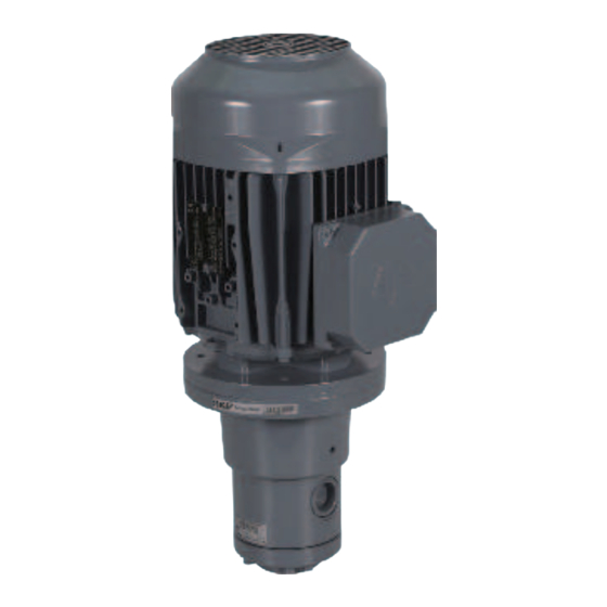
- Page 1 Operating instructions ATEX Directive 2014/34/EU ATEX-compliant gerotor pump units of series 143 for SKF CircOil centralized lubrication systems Version 03...
- Page 2 EU Declaration of Conformity EU Declaration of Conformity pursuant to ATEX Directive 2014/34/EU, Annex X The manufacturer, SKF Lubrication Systems Germany GmbH, Berlin Plant, Motzener Straße 35/37, DE -12277 Berlin, hereby declares conformity of the device Gerotor pump units Designation:...
- Page 3 Masthead Masthead Copyright Disclaimer of liability Manufacturer SKF Lubrication Systems Germany GmbH © Copyright SKF The manufacturer shall not be held liable for Address of manufacturer plants All rights reserved. damage resulting from: ○ Improper usage, assembly, Headquarters Walldorf Plant...
-
Page 4: Table Of Contents
Table of contents Table of contents ATEX-compliant gerotor pump units of series 143 Safety instructions Technical data Basic data Special safety instructions regarding Oil lubrication pump units in types IM B34 and explosion protection IM B14 Operation in potentially explosive atmospheres Explosion protection marking Delivery rates and characteristic curves Explosion protection measures... - Page 5 Table of contents Commissioning, operation Commissioning 7.1.1 Venting the pump unit 7.1.2 Inspections before initial commissioning 7.1.3 Enabling the gerotor pump unit 7.1.4 Inspections during initial commissioning Operation 7.2.1 Filling the gerotor pump units Shutdown and disposal Temporary shutdown Recommissioning after downtime Permanent shutdown and disposal Disposing of dismantled parts Maintenance and cleaning...
- Page 6 Explanation of symbols and signs Symbols used You will find these symbols, which warn of them. Please heed these instruc- Symbol Meaning specific dangers to persons, material as- tions and proceed with special sets, or the environment, next to all safety care in such cases.
-
Page 7: Safety Instructions
SKF in accordance with ATEX ognized by a notified body and accepted Directive 2014/34/EU are permitted to be by the manufacturer. If the work is not used in potentially explosive atmospheres. -
Page 8: Operation In Potentially Explosive Atmospheres
○ Unauthorized alterations The intervals are defined by the operator/ rating plate. system manufacturer. ○ Use of non-original SKF spare/ replacement components o Perform appropriate repairs in the event ○ Failure to comply with this manual and of damage, leaks, or rust. Replace the referenced documents product if necessary. -
Page 9: Intended Use
1. Safety instructions 1.7 Intended use 1.8 Foreseeable misuse ATEX gerotor pump units of SKF series 143 Any usage of the pump differing from the by taking suitable actions. The specialist has are for supplying centralized lubrication sys- conditions presented in this manual and the... -
Page 10: General Behavior When Handling The Product
1. Safety instructions 1.12 General behavior when handling 1.14 Emergency pump shut-down 1.16 Transport, assembly, servicing, the product repair, maintenance Shut down the pump in an emergency by: ○ The product may only be used in aware- ○ Switching off the machine/system in ○... -
Page 11: Initial Commissioning, Daily Startup
1. Safety instructions 1.17 Initial commissioning, daily 1.20 Provision of necessary startup information ○ All components used must be designed Ensure that: The operator must the relevant required ○ All safety mechanisms are fully present for: instructions available to all persons assigned - The maximum operating pressure and functional. -
Page 12: Information On Ce Marking
1. Safety instructions 1.22 Instruction of outside fitters 1.25 Information on CE marking Before commencing work, the operator The CE marking is based on the require- must inform outside fitters of the opera- ments of the applied Directives: tional safety regulations, applicable accident ○... -
Page 13: Existing Residual Risks
1. Safety instructions 1.26 Existing residual risks Residual risk Remedy Operating in a potentially explosive atmosphere ○ Prior to initial commissioning and then at regular intervals, inspect the varnishing and if neces- Use with non-standard-compliant varnishing sary have it replaced by a person competent to do so. The maximum permissible varnish layer of grounded metals or a conductive surface thickness is 0.2 mm and must not be exceeded under any circumstances. - Page 14 1. Safety instructions Residual risk Remedy Incorrect mounting position. ○ Install an appropriate canopy over the air inlet. - Foreign objects fall into the motor’s air inlet. Electrical shock due to reduced insulation ○ Check the insulation resistance at a regular basis. resistance.
-
Page 15: Warning Labels On The Product
1. Safety instructions 1.27 Warning labels on the product see Figure 1 The following warning labels are affixed to gerotor pump units of series 143. Before commissioning, check that the labels are present and intact. Immediately replace warning labels if damaged or missing. The product must not be operated until then. -
Page 16: Lubricants
(e.g., "bleeding"). cording to the manufacturer’s 2.2 Selection of lubricants data sheet are not suitable for Please contact SKF if you have further ques- use in centralized lubrication sys- tions regarding lubricants. SKF Lubrication Systems considers lubri- tems (e.g., incompatibility An overview of the lubricants we have cants to be an element of system design. -
Page 17: Overview, Functional Description
3. Overview, functional description 3. Overview, functional description 3.1 Assemblies Overview, Fig. 2 Item Description 1 Gerotor pump unit in flange design 1.1 Gerotor pump 1.2 Electric motor 1.3 Electric motor terminal box 1.4 Pump flange 1.5 Suction port (S), opposite pressure port (P) 2 Gerotor pump unit in foot design... -
Page 18: Order Example 143-21Fd03E-Re+1Gd
Gerotor pump unit of product series 143 (143) o Motor in foot design SKF gerotor pump units of product series 143 are used in circu- o FKM (FPM) gasket lating-oil and total-loss lubrication systems in a flow rate range of o Nominal delivery rate 1.7 l/min, back pressure 30 bar,... -
Page 19: Operation Of The Gerotor Pump Units
3. Overview, functional description 3.5 Operation of the gerotor pump units )See Figure 4 SKF gerotor pump units of product series 143 have a constant dis- placement volume and one delivery circuit. SKF CircOil centralized lubrication system, Fig. 3 The annular-toothed feeding element, also referred to as the gero- tor, is equipped with a cycloid contour, which creates a large tooth meshing length. -
Page 20: Technical Data
Total weight See Chapter 4.2 below Materials Pump housing Hydraulic cast (pressure-proof) with good wear and antifriction properties Gerotor insert Sintered material Shafts Low-deformation case-hardened steels Bearings SKF plain bearing - 20 - 951-180-074-EN Version 03, last updated 2019 / 07... -
Page 21: Oil Lubrication Pump Units In Types Im B34 And Im B14
It is important to note that temperature influences can render lubri- 12.50 cating and hydraulic oils extremely thin or viscous. 19.00 Please consult with SKF in advance if you will use lubricating and hy- 30.00 draulic oils with an operating viscosity outside the specified range. 40.00 50.00... -
Page 22: Operating Viscosity, Characteristics 20 Mm 2 /S, 50 Hz
4. Technical data 4.3 Operating viscosity, characteristics 20 mm /s, 50 Hz 4.5 Operating viscosity, characteristics 750 mm /s, 50 Hz Operating viscosity 20 mm /s, 50 Hz, Fig. 6 Operating viscosity 750 mm /s, 50 Hz, Fig. 8 † †... -
Page 23: Viscosity-Temperature Relationship Of Oils With Different Rated Viscosity
4. Technical data 4.7 Viscosity-temperature relationship of oils with different rated viscosity See Chapters 4.7.1 to 4.7.2 The curves shown in both figures are based on a viscosity index (VI) The change in the viscosity of oils is disproportionately greater in of VI ~ 95, approximately corresponding to standard mineral oil. -
Page 24: Delivery, Returns, And Storage
5.3 Storage until initial use Maximum + 40°C The following conditions apply to storage: ○ If possible, keep in original SKF shipping package Storage time of parts pre-filled with lubricant: ○ Maximum of 24 months ○ In dry, low-dust rooms ○... -
Page 25: Transporting The Gerotor Pump Unit By Forklift
5. Delivery, returns, and storage • Read the weight load of the pump unit from the motor rating plate; add a 25% safety margin to this amount. Select the hoisting IMPORTANT NOTE equipment according to this weight A gerotor pump unit with an optional attached lubricant •... -
Page 26: Assembly
6. Assembly 6. Assembly 6.1.3 Attachment The product should, to the extent possible, be protected from hu- Gerotor pump unit, Fig. 13 midity and vibration, and should be mounted so that it is easily accessible, allowing all further installation work to be done without difficulty. - Page 27 SKF recommends the use of filters for winding insulation. trouble-free operation of the pump unit. Effective filtration prevents ○...
-
Page 28: Minimum Mounting Dimensions
To flange the gerotor pump unit to a lubricant reservoir horizontally below the oil level, use a sealed pump in a special design. Consult SKF's Service department. 6.2 Minimum mounting dimensions To ensure enough space for maintenance work and for any disas- Installation examples, Fig. -
Page 29: Assembly Of Gerotor Pump Unit In Foot Design, Type Im B34
6. Assembly 6.4 Assembly of gerotor pump unit in foot design, 6.5 Assembly of gerotor pump unit in flange design, type IM B34 type IM B14 See Chapter 6.6 and “Technical data,” pages 20 to 23 See Chapter 6.6 and “Technical data,” pages 20 to 23 IMPORTANT NOTE IMPORTANT NOTE The clearance between fan and mounting surface as specified in... -
Page 30: Assembly Drawing
6. Assembly 6.6 Assembly drawing Dimensions [mm] (Fig. 15/16) Foot design Flange design Intake Pressure Motor port port frame size øPD Order No. Order No. øSD øPN øPF øFM1 øMZ øM1 SZ øSY L1 -...E... -XE... 1 /4 1 /4 71 M –... -
Page 31: Flange Design, Type Im B14, Assembly Holes And Minimum Mounting Dimensions
6. Assembly Dimensions [mm] (Fig. 15/16) ØAC 193/104 193/104 2x M25×1.5 1xM5 100 15 100 15 100 15 100 15 112 17 2xM5 100 15 1x M25×1.5 1xM5 1x M32x1.5 112 17 112 17 2xM5 112 17 2x M25×1.5 132 20 411 12 1x M32x1.5 For associated motor data, see the assembly instructions, Chapter 4, "Technical data."... -
Page 32: Electrical Motor Connection
6. Assembly 6.7 Electrical motor connection )See Figures 17 to 19 WARNING WARNING Electric shock Mains connection for explosion-proof motors Electrical connections for the product may only be estab- A mains connection in a potentially explosive atmosphere lished by qualified ATEX personnel authorized to do so by requires a motor circuit breaker or equivalent protective the operator. - Page 33 6. Assembly IMPORTANT NOTE Use only original cover fittings and original cable glands from the motor manufacturer. Improper work in the terminal box may result in property damage. Follow / comply with the following instructions to avoid this. ○ Do not damage components inside the terminal box. ○...
-
Page 34: Establishing Grounding Connection For Motor
6. Assembly 6.7.1 Establishing grounding connection for motor )See Figures 15 to 17 and Fig. 18 Connecting equipotential bonding to motor housing / direction of motor rotation, Fig. 18 WARNING Hazardous contact voltages on unit The protective earth conductor (in the motor terminal Rotation arrow box) and the equipotential bonding (on the motor hous- ing) must always be connected. -
Page 35: Lubrication Line Connection
For operating pressures up to 45 bar as can occur especially in single-line piston distributor systems, SKF fittings for solderless pipe Characteristics from rating plate, Fig. 19 unions can be used (double tapered sleeves or tapered sleeves). For... -
Page 36: Commissioning, Operation
7. Commissioning, operation 7. Commissioning, operation 7.1 Commissioning 7.1.1 Venting the pump unit Inspect all electrical and hydraulic connections before initial com- WARNING missioning of the gerotor pump unit. The intake and return lines in the lubricant reservoir must be below To ensure safety and functionality, the person speci- the minimum lubricant level in all operating states. -
Page 37: Inspections Before Initial Commissioning
7. Commissioning, operation 7.1.2 Inspections before initial commissioning Checklist for commissioning Inspections before initial commissioning Electrics Electrical connection established correctly, cables undamaged. The performance data for the aforementioned connections matches the specifications in “Technical data.” Cable gland properly implemented and sealed. - See operating instructions from motor manufacturer. The voltage and frequency of the mains network match the specifications on the rating plate of the motor/pump. -
Page 38: Operation
7. Commissioning, operation 7.2 Operation Immediately switch off the gerotor pump unit if any irregularities are SKF centralized lubrication systems operate largely automatically. identified during commissioning/operation. Determine and remedy The activities required during normal operation are limited primarily the cause of the malfunction with the aid of Chapter 10, “Malfunc- to inspection of the fill level and timely refilling of lubricant. -
Page 39: Shutdown And Disposal
Plastic or metallic parts: storage.” Can be disposed of as industrial waste. The product can also be returned to SKF Lubrication Systems Ger- many GmbH for disposal, in which case the customer is responsible for reimbursing the costs incurred. 8.2 Recommissioning after downtime To recommission the product, follow the instructions in Chapter 6, “Assembly.”... -
Page 40: Maintenance And Cleaning
Note the following: ○ Unlock the gerotor pump unit. ○ Only SKF Lubrication Systems Germany GmbH, Berlin Plant (see ○ Lock the gerotor pump unit to prevent it from being restarted. masthead) or an ATEX specialist firm authorized by the Service ○... -
Page 41: Maintenance Checklist
Varnishing is fully present. unit in accordance with ATEX requirements. Pump motor bearings - 4-pole motors at max. Have the bearings or motor replaced by SKF For further information, see the operating instruc- 40,000 operating hours Service. tions from the motor manufacturer. -
Page 42: Cleaning
9. Maintenance, cleaning 10. Malfunctions, causes, and remedies 9.4 Cleaning 10.1 Prior to beginning troubleshooting In cases of functional failure, always check whether all technical specifications have been adhered in the existing operating WARNING conditions. Risk of death Fire and explosion hazard from the use of flammable 10.2 Safety measures before maintenance work cleaning agents. -
Page 43: Commissioning, Product, And System Malfunctions
• Clean the fan slots PTC thermistor or ○ Gerotor pump unit is jammed • Have the gerotor pump unit replaced by SKF Service motor circuit breaker does not switch • Comply with the technical data for the pump unit and pump ○... -
Page 44: Supplier Documentation With Declarations Of Conformity
11. Supplier documentation with Declarations of Conformity 11. Supplier documentation with Declarations of Conformity 11.1 Supplier documentation The following supplier documentation is included with these operating instructions (gerotor pump unit of series 143): Operating instructions for three-phase motors with flameproof enclosures II 2G Ex db IIC T3...T6 Gb Ex db eb IIC T3...T6 Gb 0044... -
Page 45: Declaration Of Conformity For Motor
11. Supplier documentation with Declarations of Conformity 11.3 Declaration of Conformity for motor - 45 - 951-180-074-EN Version 03, last updated 2019 / 07... - Page 46 11. Supplier documentation with Declarations of Conformity - 46 - 951-180-074-EN Version 03, last updated 2019 / 07...
- Page 47 11. Supplier documentation with Declarations of Conformity - 47 - 951-180-074-EN Version 03, last updated 2019 / 07...
- Page 48 The Power of Knowledge Engineering Bearings Lubrication and Bearing Over the course of more than a century, SKF has specialized in five fields of competence and Seals Systems Units acquired a wide range of application expertise. We utilize this experience to provide innova- tive solutions to OEMs and other manufacturers in practically all industrial sectors worldwide.
Need help?
Do you have a question about the 143 Series and is the answer not in the manual?
Questions and answers