
Related Manuals for Advantech PPC-3150SW-PN4A


Summary of Contents for Advantech PPC-3150SW-PN4A
- Page 1 User Manual PPC-3150SW-PN4A/ PPC-3180SW-PN4A 15.6/18.5” Panel PC with TFT LCD and Intel® Pentium® N4200 Processor...
- Page 2 No part of this manual may be reproduced, copied, translated, or transmitted in any form or by any means without the prior written permission of Advantech Co., Ltd. The information provided in this manual is intended to be accurate and reliable.
- Page 3 This product has passed the CE test for environmental specifications when shielded cables are used for external wiring. We recommend the use of shielded cables. This type of cable is available from Advantech. Please contact your local supplier for ordering information.
- Page 4 70 dB (A). DISCLAIMER: These instructions are provided according to IEC 704-1 stan- dards. Advantech disclaims all responsibility for the accuracy of any statements contained herein. This product is intended to be supplied by an UL-certified power supply or DC power source suitable for use at TMA: 50 °C minimum (with an SSD) or TMA:...
- Page 5 CAUTION: This equipment is not intended for use by children (this product is not a toy) and is not suitable for use in locations where children are likely to be present. ATTENTION: Ce produit n'est pas un jouet et devrait être gardé hors de la por- tée des enfants.
- Page 6 Safety Precaution - Static Electricity Follow these simple precautions to protect yourself from harm and the products from damage. To avoid electrical shock, always disconnect the power from the PC chassis before manual handling. Do not touch any components on the CPU card or other cards while the equipment is powered on.
-
Page 7: Table Of Contents
Front Panel....................2 Figure 1.1 Front Panel ..............2 Rear Panel ....................3 Figure 1.2 Rear Panel..............3 Dimensions ....................4 Figure 1.3 PPC-3150SW-PN4A Dimensions....... 4 Figure 1.4 PPC-3180SW-PN4A Dimensions....... 4 Specifications .................... 5 Ordering Information ................. 6 Chapter System Installation and Setup ...7... - Page 8 Chapter Software Setup........29 Driver Installation ..................30 BIOS Setup Program ................30 4.2.1 Entering the BIOS Utility ............. 30 4.2.2 LCD Brightness Settings............. 31 4.2.3 COM2 Mode Selection (RS-232/422/485) ........33 4.2.4 OS Selection................35 4.2.5 BIOS AT/ATX Setup ..............36 4.2.6 Wake-on-LAN ................
-
Page 9: Chapter 1 General Information
Chapter General Information Introduction Specifications Dimensions... -
Page 10: Introduction
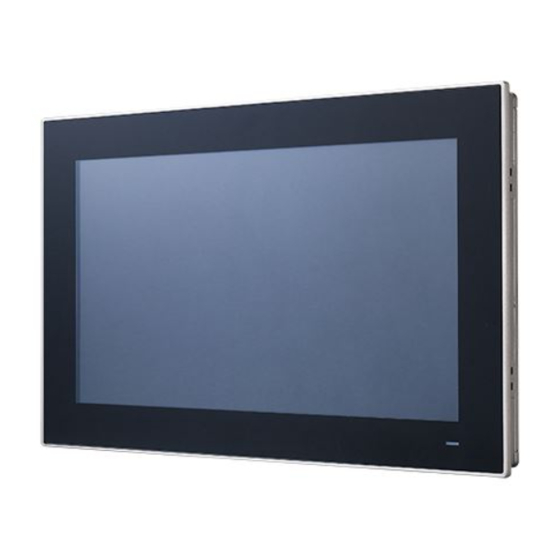
The PPC-3150SW/3180SW-PN4A front panel is a true-flat color TFT LCD with multi- touch projected capacitive touch control. Additionally, the front panel is IP65 rated for protection from dust and water ingress. Note! Figure 1.1 shows the PPC-3150SW-PN4A model. The PPC-3150SW/ 3180SW-XN4X models all follow the same design. Aluminium bezel Touchscreen... -
Page 11: Rear Panel
Rear Panel The PPC-3150SW/3180SW-PN4A rear panel features four VESA mount holes (75 x 75 mm) as shown in Figure 1.2. Speaker Speaker Figure 1.2 Rear Panel VESA Screw Specifications Screw Type: M4 Screw Depth:12 mm max. Screw Quantity: 4 PPC-3150SW_3180SW User Manual... -
Page 12: Dimensions
Dimensions 410.96 419.70 75.00 Cutout dimensions: 413 x 262 mm Figure 1.3 PPC-3150SW-PN4A Dimensions 477.72 488.00 75.00 Cutout dimensions: 479.3 x 300.3 mm Figure 1.4 PPC-3180SW-PN4A Dimensions PPC-3150SW_3180SW User Manual... -
Page 13: Specifications
Specifications PPC-3150SW-PN4A PPC-3180SW-PN4A LCD Size 15.6” 18.5” Display Type TFT LCD TFT LCD Max. Resolution 1366 x 768 1366 x 768 Brightness Color 16.7M 16.7M Pixel Pitch 252 x 252 300 x 300 Viewing Angle 170, 165 170, 160 Contrast... -
Page 14: Ordering Information
OS: Windows 10 (64 bit) Software: Burn In Test 8.1 Ordering Information Part Number Description Image Intel® Pentium® APL N4200 PPC-3150SW-PN4A PPC-3180SW-PN4A Fanless 15.6/18.5” panel PC Power adapter 100 ~ 240 V 96PSA-A90W19OT-1 90 W, 19V with PFC PPC-WLAN-B1E Wi-Fi module with antenna... -
Page 15: Chapter 2 System Installation And Setup
Chapter System Installation and Setup Quick System Tour Memory Card Installation HDD Installation mSATA Installation Wireless LAN Card Installation System Mounting... -
Page 16: Quick System Tour
Quick System Tour Before setting up the panel PC, take a moment to identify the locations of the device controls, drives, connectors, and ports (as shown in Figure 2.3). When placed upright, the PPC-3150SW/3180SW-PN4A front panel should appear as shown in Figure 2.1. -
Page 17: Installation Procedures
Figure 2.3 I/O Ports Installation Procedures The system installation procedures should be conducted in the following order: Install a SATA HDD or mSATA storage Install a memory card Install a wireless LAN module Mount the panel PC 2.2.1 HDD Installation Loosen and remove the 9 retention screws on the rear cover. - Page 18 Loosen and remove the 4 retention screws on the HDD bracket. Remove the HDD bracket. Install a SATA HDD and affix in place using 4 retention screws Close the HDD cover and affix in place using 4 retention screws PPC-3150SW_3180SW User Manual...
-
Page 19: Msata Installation
Connect the SATA cable to the motherboard. 2.2.2 mSATA Installation Insert an mSATA card into the mSATA socket. Secure the mSATA module using 2 retention screws provided in the accessory box. PPC-3150SW_3180SW User Manual... -
Page 20: Memory Card Installation
2.2.3 Memory Card Installation Insert the memory card into the slot highlighted by the red box in the image below. Then install the memory and CPU thermal pads provided in the acces- sory box. PPC-3150SW_3180SW User Manual... -
Page 21: Wireless Lan Module Installation
2.2.4 Wireless LAN Module Installation 2.2.4.1 Full-Size Mini PCIe Card Installation Insert the full-size mini PCIe card into the socket. Secure the card in place using one of the retention screws provided in the accessory box. 2.2.4.2 Half-Size Mini PCIe Card Installation Retrieve the hexagonal screw provided in the accessory box. - Page 22 Insert the half-size mini PCIe card into the socket at an angle. Secure the card in place using a screw from the accessory box. Connect the antenna cables and affix them to the brackets. Take note of the cable routing. Remove the two rubber plugs on the rear cover.
-
Page 23: System Mounting
Install the external antenna. System Mounting Warning! More than one person should participate in mounting the panel PC to prevent accidental damage to the panel or personal injury. Le comité constate qu'el-nasr mounting, plus d'une personne installation to prevent the cadre accidental damage to personal injury. The PPC-3150SW/3180SW-PN4A panel PC supports various mounting options. - Page 24 Remove the original screws at the rear of the panel PC. Secure the bracket to the rear panel using four M4 screws. Figure 2.5 Rear Panel Screw Locations Warning! Ensure that the screw thread depth does not exceed 4 mm. Assurez-vous que la profondeur du filetage des vis sur le panneau arri- èrene dépasse pas 4 mm.
-
Page 25: Panel Mounting
To mount the flat bezel panel PC into a panel, follow the steps below. Prepare a panel cutout that corresponds to the device size, (413 x 262 mm (16.25 x 10.31 in) for PPC-3150SW-PN4A, 479.3 x 300.3 mm (18.87 x 11.82 in) for PPC-3180SW-PN4A). - Page 26 4. Tighten the screws in the hook brackets to secure the panel PC in place. Figure 2.10 Fastening Hook Bracket Screws Figure 2.11 Panel Mount Rear View PPC-3150SW_3180SW User Manual...
-
Page 27: Arm Mounting
2.3.3 Arm Mounting PPC-3150SW/3180SW-PN4A can be mounted on a VESA-compliant arm mount with a 100-mm pad. To affix the panel PC to an arm mount, follow the steps outlined below. Refer to the mounting arm’s installation instructions to correctly mount the arm onto the surface as a base. -
Page 28: Stand Mounting
2.3.4 Stand Mounting Before stand mounting, check that the items listed below were included with your shipment. To mount the panel PC onto a stand, follow the steps outlined below Remove the four original screws at the rear of the machine. Use four M4 x 8L screws to affix the VESA bracket to the panel PC. - Page 29 Use four M4 x 8L screws to secure the base plate to the mount stand. Figure 2.14 Securing the VESA Mount Base Use four M4 x 6L screws to secure the mount stand to the VESA mount bracket. Figure 2.15 Securing the VESA Mount Bracket PPC-3150SW_3180SW User Manual...
- Page 30 Use one M4 x 5L screw to attach the stand mount hinge cover. Figure 2.16 Stand Mount Hinge Cover Figure 2.17 Completed Stand Mount PPC-3150SW_3180SW User Manual...
-
Page 31: Chapter 3 Jumper Setting
Chapter Jumper Setting Motherboard Layout Jumpers and Connectors External COM Ports and Pin Definitions... -
Page 32: Motherboard Layout
Motherboard Layout The PPC-3150SW/3180SW-PN4A motherboard features internal peripheral connec- tors that can be accessed when the motherboard is outside of the chassis. Figure 3.1 shows the locations of the internal peripheral connectors on the motherboard. Figure 3.1 Motherboard Layout Diagram Connectors Functions LPC conn... -
Page 33: Jumpers And Connectors
Jumpers and Connectors Icon RTC Reset (2~3) Normal (default) (3~4) CMOS clear Icon Backlight Power Selection (1~2) (2~3) 3.3V (default) Icon Backlight PWM Power Selection (1~2) (2~3) 3.3V (default) Icon Touch Power Selection (1~2) Closed P8 3.3VSB (1~2) Open Resistive touch disabled (default) PPC-3150SW_3180SW User Manual... - Page 34 Icon ATX/AT Selection (1~2) AT power (2~3) ATX power (default) Icon COM1 Ring and Power Selection (1~2) COM1 RI (default) (3~4) COM1 5V (4~5) COM1 12V Icon Panel Resolution 1,2,3 ON; 4 1366 x 768 (24 bit) for PPC-3180SW 1,2,3 OFF; 4 1366 x 768 (24 bit) for PPC-3150SW PPC-3150SW_3180SW User Manual...
-
Page 35: External Com Port Pin Definition
External COM Port Pin Definition 3.3.1 COM1: RS-232; COM2: RS-232/422/485 COM1 COM2 COM2_422_485_TX- COM2_422_485_TX+ COM2_422_RX+ COM2_422_RX- Ring or 5V/12V output Ring PPC-3150SW_3180SW User Manual... - Page 36 PPC-3150SW_3180SW User Manual...
-
Page 37: Software Setup
Chapter Software Setup Driver Installation BIOS Setup Program... -
Page 38: Driver Installation
Driver Installation Before installing software on the panel PC, install the corresponding drivers to ensure full functionality. All drivers can be downloaded from the Advantech website at http://www.advantech.com. BIOS Setup Program 4.2.1 Entering the BIOS Utility During system bootup, press the <Del> button to enter the BIOS setup utility. -
Page 39: Lcd Brightness Settings
4.2.2 LCD Brightness Settings Select the “North Bridge” item in the “Chipset” tab. Then select “LCD Control”. PPC-3150SW_3180SW User Manual... - Page 40 Select “Brightness Mode Control”. There are six brightness levels available.Select the level most suitable for your application needs. PPC-3150SW_3180SW User Manual...
-
Page 41: Com2 Mode Selection (Rs-232/422/485)
4.2.3 COM2 Mode Selection (RS-232/422/485) Select the “NCT6116D Super IO Configuration” option in the “Advanced” tab. Select “Serial Port 2 Configuration”. PPC-3150SW_3180SW User Manual... - Page 42 Navigate to the “Serial Port 2 Mode” item and double click to set the COM2 operation mode as [RS-422] or [RS-485]. When COM2 Mode is set as RS-485, the “RS-485 Auto Flow” item can be con- figured as [enabled] or [disabled] PPC-3150SW_3180SW User Manual...
-
Page 43: Os Selection
When COM3 Mode is set as RS-485, the “Serial Port3 Terminal” can be config- ured as [enabled] or [disabled] 4.2.4 OS Selection Select the “South Bridge” item in the “Chipset” tab. PPC-3150SW_3180SW User Manual... -
Page 44: Bios At/Atx Setup
The system supports different OS [Windows/Android/Intel Linux]. Navigate to the “OS Selection” item to set the system OS. 4.2.5 BIOS AT/ATX Setup Select the “South Cluster Configuration” item in the “Chipset” tab. PPC-3150SW_3180SW User Manual... - Page 45 Select the “Miscellaneous Configuration” item. Configure the “Restore AC Power Loss” item as “Power On” when in “AT Mode” and as “Power Off” for “ATX Mode”. PPC-3150SW_3180SW User Manual...
-
Page 46: Wake-On-Lan
4.2.6 Wake-on-LAN Select the “South Cluster Configuration” item in the “Chipset” tab. Select the “Miscellaneous Configuration” item. PPC-3150SW_3180SW User Manual... -
Page 47: Wake-On-Ring
Set “Wake-on-PCIE” as “enabled”. 4.2.7 Wake-on-Ring Select the “NCT6106D Super IO Configuration” item in the “Advanced” tab. PPC-3150SW_3180SW User Manual... - Page 48 Set “Wake-on-Ring” to “enabled”. PPC-3150SW_3180SW User Manual...
-
Page 49: Appendix A Watchdog Timer Programming
Appendix Watchdog Timer Programming... -
Page 50: Watchdog Timer Programming Example
Watchdog Timer Programming Example The watchdog timer is provided to ensure that standalone systems can always recover from catastrophic CPU failures and crashes. Such events may have been caused by external EMI or a software bug. If the CPU is malfunctioning, the watch- dog timer performs a hardware reset to return the system to a previous state. - Page 51 ;----------------------------------------------------------------------------- MOV DX, 2EH MOV AL, F1H OUT DX, AL MOV DX, 2FH MOV AL, 05H OUT DX, AL; set timeout value as 5s; 00 = timeout disabled ;----------------------------------------------- ; Exit the Extended Function Mode ;---------------------------------------------- MOV DX, 2EH MOV AL, AAH OUT DX, AL PPC-3150SW_3180SW User Manual...
- Page 52 No part of this publication may be reproduced in any form or by any means, such as electronically, by photocopying, recording, or otherwise, without prior written permission from the publisher. All brand and product names are trademarks or registered trademarks of their respective companies. © Advantech Co., Ltd. 2019...
Need help?
Do you have a question about the PPC-3150SW-PN4A and is the answer not in the manual?
Questions and answers