Table of Contents
Advertisement
Quick Links
Operating Manual
Product Features:
•
2x analogue input for current (0...20mA or 4...20mA - adjustable)
•
2x analogue input for voltage (-10V ... +10V)
•
High-precision reference output +10 V for potentiometer (> 1 kOhm)
•
Simple device parameterization possible via IO-Link using various engineering tools
•
Switchable averaging and adjustable sampling intervals for each analog input
•
Adjustable limit value monitoring possible for each input
•
Numerous connection options via expansion option (IO220/CO) (three additional control
inputs and two additional control outputs)
•
Generation of pending events (e.g. threshold value exceeded, line break, ... ) possible
•
Compact rail housing to EN60715
Available Options:
IO220:
Basic device with 4 analog inputs (16 bit) and reference output
IO220/CO:
Basic device with 4 analog inputs (16 bit), reference output and additional 3x
HTL PNP control inputs and 2x PNP control outputs
motrona GmbH, Zeppelinstraße 16, DE - 78244 Gottmadingen, Tel. +49 (0) 7731 9332-0, Fax +49 (0) 7731 9332-30, info@motrona.de, www.motrona.de
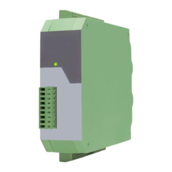
Signal converter IO220 and IO220/CO
4x analog input → IO – Link (V1.1)
Advertisement
Table of Contents

Subscribe to Our Youtube Channel
Related Manuals for Motrona IO220


Summary of Contents for Motrona IO220
- Page 1 Basic device with 4 analog inputs (16 bit), reference output and additional 3x HTL PNP control inputs and 2x PNP control outputs motrona GmbH, Zeppelinstraße 16, DE - 78244 Gottmadingen, Tel. +49 (0) 7731 9332-0, Fax +49 (0) 7731 9332-30, info@motrona.de, www.motrona.de...
- Page 2 First Version Legal notices: All contents included in this manual are protected by the terms of use and copyrights of motrona GmbH. Any reproduction, modification, usage or publication in other electronic and printed media as well as in the internet requires prior written authorization by motrona GmbH.
-
Page 3: Table Of Contents
Inhaltsverzeichnis Safety Instructions and Responsibility ................4 General Safety Instructions ......................4 Use according to the intended purpose ..................4 Installation ............................5 EMC Guidelines ..........................6 Cleaning, Maintenance and Service Notes..................6 Introduction ........................7 Function diagram ..........................8 Electrical Connections .................... -
Page 4: Safety Instructions And Responsibility
Safety Instructions and Responsibility General Safety Instructions This operation manual is a significant component of the unit and includes important rules and hints about the installation, function and usage. Non-observance can result in damage and/or impairment of the functions to the unit or the machine or even in injury to persons using the equipment! Please read the following instructions carefully before operating the device and observe all safety and warning instructions! Keep the manual for later use. -
Page 5: Installation
Installation The device is only allowed to be installed and operated within the permissible temperature range. Please ensure an adequate ventilation and avoid all direct contact between the device and hot or aggressive gases and liquids. Before installation or maintenance, the unit must be disconnected from all voltage-sources. Further it must be ensured that no danger can arise by touching the disconnected voltage-sources. -
Page 6: Emc Guidelines
Run signal and control cables apart from power lines and other cables emitting electromagnetic • noise. Please also refer to motrona manual “General Rules for Cabling, Grounding, Cabinet Assembly”. You can download that manual by the link https://www.motrona.com/en/support/general-certificates.html Cleaning, Maintenance and Service Notes To clean the front of the unit please use only a slightly damp (not wet!), soft cloth. -
Page 7: Introduction
Introduction The device can be used as a signal converter for analog standard signals (-10 ... +10 V or 0/4 ... 20 mA), which are to be transmitted as cyclic process values via IO-Link. In addition to its four analog inputs (two fixed as voltage inputs and the other two fixed as current inputs), the signal converter has a high-precision reference output (+10.00 V ±... -
Page 8: Function Diagram
Function diagram Io220_01a_oi_e.docx / Jul-23 Seite 8 / 34... -
Page 9: Electrical Connections
Electrical Connections The terminal screws should be tightened with a slotted screwdriver (blade width 2mm). DC Power Supply The unit accepts DC supply from 18 to 30 V at the terminals X1 pin 7 (+) und 8 (-). The power consumption depends on the level of the supply voltage with approx. -
Page 10: Analog Inputs
Analog Inputs The reference potential (AGND) for the analog inputs is connected to terminal X2 pin 4 and pin 7. Two 16-bit analog inputs are available on terminal X2, pins 3 and 6. These are firmly designed as voltage inputs. Two additional 16-bit analog inputs are available on terminal X2, pins 5 and 8. These are firmly designed as current inputs. -
Page 11: Control Inputs (Only With Option „Co")
Control Inputs (only with option „CO“) Three control inputs with HTL PNP characteristics are available on terminal X1, pins 1, 2 and 3. The current state of the control inputs is cyclically exchanged with the process data and can therefore be used for a wide variety of functions. -
Page 12: Control Outputs (Only With Option "Co")
Control Outputs (only with option “CO“) Two control outputs are available on terminal X1, pins 5 and 6. These signal, when limit values defined by the user have been undercut or exceeded. Control output 1 always reacts as soon as the lower limit value is undercut. -
Page 13: Io-Link Interface
IO-Link Interface This chapter contains important notes and information regarding IO-Link communication data. In addition to general information on the IO-Link connection, the parameter data of the device, the exchanged process data and the implemented system commands, error codes and events are discussed. -
Page 14: Connection Of The Io Link Interface
Device ID 2162945 / 0x210101 Vendor Name motrona GmbH Vendor Text http://www.motrona.de Product Name signalconverter Product ID IO220 oder IO220/CO analog converter with Product Text IO-Link interface Serial Number Hardware Revision z.B.: 224IO11 Firmware Revision z.B.: IO22001A Application Specific Tag Max. - Page 15 Continuation “Parameter data”: ISDU DPP1 Length Name of the Parameter Access Default Value Range Index Index in bytes GENERAL MENU OUTPUT SOURCE 0..3 INPUT CONFIGURATION 0..3 INPUT ACTIVATION 0..15 DIAGNOSIS SETUP 0 (0x0000) 0..32767 IN 1 (V) PROPERTIES SAMPLING TIME (S) 1..60000 AVERAGE FILTER 0..4...
-
Page 16: System Commands
System Commands A system command is a write-only parameter that causes an action in the device. To invoke the desired action, the corresponding value must be written to index 2, subindex 0. If the desired command is a static command (s), this command remains active until the corresponding value is written again to index 2, subindex 0. -
Page 17: Io-Link Process Data
IO-Link Process data Process input data (Total: 11 Byte): (View from the IO-link master) Byte Subindex Description Bit 0 Diagnosis: Upper set threshold (Upper Limit) exceeded - (Input1_V) Bit 1 Diagnosis: Below the lower set threshold value (Lower Limit) - (Input1_V) Bit 2 Diagnosis: Upper set threshold (Upper Limit) exceeded - (Input2_V) Bit 3... -
Page 18: Measuring Ranges Of The Analog Process Values
Measuring ranges of the analog process values Nominal measuring range Max. measuring range Input resistance Value (1 LSB) 0…20 mA 0… 20.997 mA 100 Ohm 641 nA 4…20 mA 0… 20.996 mA 100 Ohm 641 nA -10V … +10V -10.498 V … +10.498 V 1 MOhm 320 µV Measuring ranges of the analog inputs... -
Page 19: Error Types
Error types Error code Name Description Access was denied by the device. No 32768 / 0x 8000 Application errors in the device-no details detailed information is available. 32785 / 0x 8011 Index does not exist Access to a non-existent index. 32786 / 0x 8012 Subindex does not exist Access to a non-existent subindex.. -
Page 20: Events
Events Device Code Status Bedingung 0x00 0x1800 Warning Diagnosis: Upper set threshold (Upper Limit) exceeded - (Input1_V) 0x00 0x1801 Warning Diagnosis: Below the lower set threshold value (Lower Limit) - (Input1_V) 0x00 0x1802 Warning Diagnosis: Upper set threshold (Upper Limit) exceeded - (Input2_V) 0x00 0x1803 Warning... -
Page 21: Parameter / Overview - Menu Structure
Parameter / Overview - Menu Structure The device is parameterized via the IO-Link interface using a suitable engineering tool, which is usually provided by the IO-Link master manufacturers. This section shows the overview of the individual menus and their parameters. The menu name is written in bold, the associated parameters are arranged directly under the menu name. -
Page 22: General Menu
General Menu The general parameters for this signal converter are described in this menu. OUTPUT SOURCE This parameter defines the reference source to which the two switching outputs should react during limit value monitoring. INPUT 1 (Voltage) Reference source is input 1 (voltage). INPUT 2 (Voltage) Reference source is input 2 (voltage). - Page 23 Continuation „General Menu“: DIAGNOSIS SETUP This parameter can be used to specify which "events" are to be generated by the device. Corresponding bit = 1→ associated event is generated as soon as the event is pending (appears) or is no longer pending (disappears).
-
Page 24: In 1 (V) Properties
In 1 (V) Properties The respective parameters for voltage input 1 are described in this menu. SAMPLING TIME (S) The value set here corresponds to the sampling interval of the analog input. This interval defines the time interval in seconds between the individual samples of the analog signal. 0,001 Shortest sampling time 0,01... - Page 25 Continuation „In 1 (V) Properties“: HYSTERESE LOWER LIMIT This parameter defines a hysteresis for the lower limit value. Smallest value Default value +32767 Highest value If the value set in "LOWER LIMIT" plus the hysteresis set here is exceeded, control output 1 is reset (if "OUTPUT SOURCE"...
-
Page 26: In 2 (V) Properties
In 2 (V) Properties The respective parameters for voltage input 2 are described in this menu. SAMPLING TIME (S) The value set here corresponds to the sampling interval of the analog input. This interval defines the time interval in seconds between the individual samples of the analog signal. 0,001 Shortest sampling time 0,01... - Page 27 Continuation „In 2 (V) Properties“: HYSTERESE LOWER LIMIT This parameter defines a hysteresis for the lower limit value. Smallest value Default value +32767 Highest value If the value set in "LOWER LIMIT" plus the hysteresis set here is exceeded, control output 1 is reset (if "OUTPUT SOURCE"...
-
Page 28: In 1 (C) Properties
In 1 (C) Properties The respective parameters for current input 1 are described in this menu. SAMPLING TIME (S) The value set here corresponds to the sampling interval of the analog input. This interval defines the time interval in seconds between the individual samples of the analog signal. 0,001 Shortest sampling time 0,01... - Page 29 Continuation „In 1 (C) Properties“: HYSTERESE LOWER LIMIT This parameter defines a hysteresis for the lower limit value. Smallest value Default value +32767 Highest value If the value set in "LOWER LIMIT" plus the hysteresis set here is exceeded, control output 1 is reset (if "OUTPUT SOURCE"...
-
Page 30: In 2 (C) Properties
In 2 (C) Properties The respective parameters for current input 2 are described in this menu. SAMPLING TIME (S) The value set here corresponds to the sampling interval of the analog input. This interval defines the time interval in seconds between the individual samples of the analog signal. 0,001 Shortest sampling time 0,01... - Page 31 Continuation „In 2 (C) Properties“: HYSTERESE LOWER LIMIT This parameter defines a hysteresis for the lower limit value. Smallest value Default value +32767 Highest value If the value set in "LOWER LIMIT" plus the hysteresis set here is exceeded, control output 1 is reset (if "OUTPUT SOURCE"...
-
Page 32: Attachment
Attachment Parameter / serial codes Menu Name Ser.Code Default GENERAL MENU FACTORY SETTINGS GENERAL MENU OUTPUT SOURCE GENERAL MENU INPUT CONFIGURATION GENERAL MENU INPUT ACTIVATION GENERAL MENU DIAGNOSIS SETUP 32767 IN 1 (V) PROPERTIES SAMPLING TIME (S) 60000 IN 1 (V) PROPERTIES AVERAGE FILTER IN 1 (V) PROPERTIES LOWER LIMIT... -
Page 33: Dimensions
Dimensions Dimensions in mm [inch] Io220_01a_oi_e.docx / Jul-23 Seite 33 / 34... -
Page 34: Technical Specifications
Failure rate: MTBF in years: IO220: 102,7 a (continuous operation at 60 °C) IO220/CO: 92,9 a Conformity and standards: EMC 2014/30/EU: EN 61326-1: 2013 for industrial location EN 55011: 2016 + A1: 2017 + A11: 2020 Class A RoHS (Ⅱ) 2011/65/EU RoHS (Ⅲ) 2015/863:...
Need help?
Do you have a question about the IO220 and is the answer not in the manual?
Questions and answers