Table of Contents
Advertisement
Quick Links
Operating Manual
Product Features:
•
1x strain gauge input for connecting a strain gauge full bridge sensor
•
Simple device parameterization via IO-Link possible using various engineering tools
•
Numerous connection options via expansion option (IO221/CO) (three additional control
inputs and two additional control outputs)
•
Adjustable limit value monitoring possible
•
Generation of pending events (e.g. calculated bridge resistance above or below the set target
resistance, bridge current > 50 mA, undervoltage, ...) possible
•
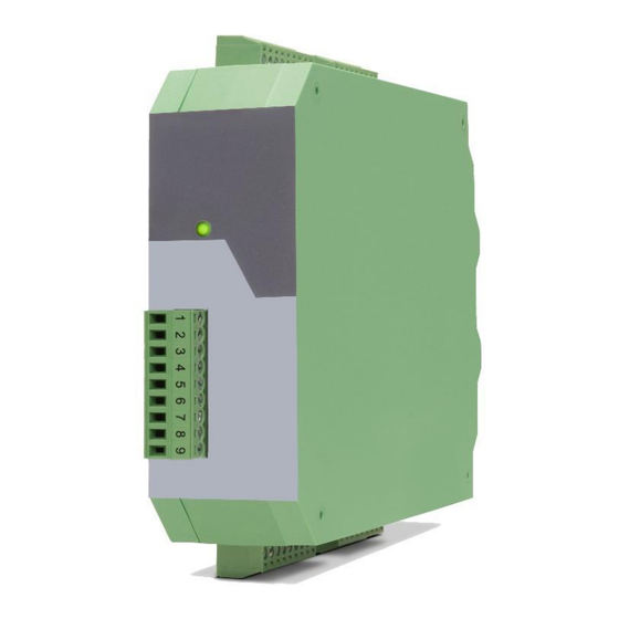
Compact rail housing to EN60715
Available Options:
IO221:
Basic device with strain gauge input for a strain gauge full bridge sensor
IO221/CO:
Basic device with strain gauge input for a strain gauge full bridge sensor and
additional 3x HTL PNP control inputs and 2x PNP control outputs
motrona GmbH, Zeppelinstraße 16, DE - 78244 Gottmadingen, Tel. +49 (0) 7731 9332-0, Fax +49 (0) 7731 9332-30, info@motrona.de, www.motrona.de
Signal converter IO221 and IO221/CO
DMS input → IO – Link (V1.1)
Advertisement
Table of Contents

Related Manuals for Motrona IO221


Summary of Contents for Motrona IO221
- Page 1 Basic device with strain gauge input for a strain gauge full bridge sensor and additional 3x HTL PNP control inputs and 2x PNP control outputs motrona GmbH, Zeppelinstraße 16, DE - 78244 Gottmadingen, Tel. +49 (0) 7731 9332-0, Fax +49 (0) 7731 9332-30, info@motrona.de, www.motrona.de...
- Page 2 First Version Legal notices: All contents included in this manual are protected by the terms of use and copyrights of motrona GmbH. Any reproduction, modification, usage or publication in other electronic and printed media as well as in the internet requires prior written authorization by motrona GmbH.
-
Page 3: Table Of Contents
Inhaltsverzeichnis Safety Instructions and Responsibility ................5 General Safety Instructions ......................5 Use according to the intended purpose ..................5 Installation ............................6 EMC Guidelines ..........................7 Cleaning, Maintenance and Service Notes..................7 Introduction ........................8 Function diagram ..........................9 Electrical Connections .................... - Page 4 Dimensions ............................ 41 Technical Specifications ........................ 42 Io221_01a_oi_e.docx / Jul-23 Seite 4 / 42...
-
Page 5: Safety Instructions And Responsibility
Safety Instructions and Responsibility General Safety Instructions This operation manual is a significant component of the unit and includes important rules and hints about the installation, function and usage. Non-observance can result in damage and/or impairment of the functions to the unit or the machine or even in injury to persons using the equipment! Please read the following instructions carefully before operating the device and observe all safety and warning instructions! Keep the manual for later use. -
Page 6: Installation
Installation The device is only allowed to be installed and operated within the permissible temperature range. Please ensure an adequate ventilation and avoid all direct contact between the device and hot or aggressive gases and liquids. Before installation or maintenance, the unit must be disconnected from all voltage-sources. Further it must be ensured that no danger can arise by touching the disconnected voltage-sources. -
Page 7: Emc Guidelines
Run signal and control cables apart from power lines and other cables emitting electromagnetic • noise. Please also refer to motrona manual “General Rules for Cabling, Grounding, Cabinet Assembly”. You can download that manual by the link https://www.motrona.com/en/support/general-certificates.html Cleaning, Maintenance and Service Notes To clean the front of the unit please use only a slightly damp (not wet!), soft cloth. -
Page 8: Introduction
Introduction The IO221 or the IO221/CO are devices for connecting a strain gauge full bridge sensor, the converted measurement result of which is transmitted cyclically via the process data via IO Link. The "CO" expansion option also has three HTL PNP control inputs and two PNP switching outputs. These switching outputs transmit when switching points are exceeded or fallen below, as well as movements outside of a range. -
Page 9: Function Diagram
Function diagram Io221_01a_oi_e.docx / Jul-23 Seite 9 / 42... -
Page 10: Electrical Connections
Electrical Connections The terminal screws should be tightened with a slotted screwdriver (blade width 2mm). DC Power Supply The unit accepts DC supply from 18 to 30 V at the terminals X1 pin 7 (+) und 8 (-). The power consumption depends on the level of the supply voltage with approx. -
Page 11: Dms Input
DMS Input Strain gauge full bridge supply With the terminals SUP+, SUP- resp. X3 Pin 5 (+) and Pin 4 (-) the DMS sensor can be supplied by a programmable voltage of 3V - 10VDC with max. 50mA. The supply voltage can be read back in mV via Index „40“, Subindex „19“... -
Page 12: Control Inputs (Only With Option „Co")
Control Inputs (only with option „CO“) Three control inputs with HTL PNP characteristics are available on terminal X1, pins 1, 2 and 3. The current state of the control inputs is cyclically exchanged with the process data and can therefore be used for a wide variety of functions. -
Page 13: Control Outputs (Only With Option „Co")
Control Outputs (only with option „CO“) Two control outputs are available on terminal X1, pins 5 and 6. Depending on the configuration ("DIGITAL OUTPUT MENU"), they can transmit different statuses. The outputs Ctrl. Out 1 and 2 are designed as high side drivers. The status of the outputs is transmitted cyclically with the IO-Link process data. -
Page 14: Io-Link Interface
IO-Link Interface This chapter contains important notes and information regarding IO-Link communication data. In addition to general information on the IO-Link connection, the parameter data of the device, the exchanged process data and the implemented system commands, error codes and events are discussed. -
Page 15: Connection Of The Io Link Interface
Device ID 2228481 / 0x220101 Vendor Name motrona GmbH Vendor Text http://www.motrona.de Product Name signal amplifier Product ID IO221 oder IO221/CO DMS amplifier with IO- Product Text Link interface Serial Number Hardware Revision z.B.: 224IO11 Firmware Revision z.B.: IO22101A Application Specific Tag Max. - Page 16 Continuation “Parameter data”: ISDU DPP1 Length Name of the Parameter Access Default Value Range Index Index in bytes SENSOR MENU SENSOR SUPPLY 3..10 SENSOR GAIN 0..4 SENSOR OSR 0..12 SENSOR OFFSET -10000..10000 SENSOR RESISTOR 0..10000 SENSOR SENSITIVITY 1000 100..20000 SENSOR VOLTAGE 1000 1..99999 SENSOR DIGIT...
- Page 17 Continuation “Parameter data”: ISDU DPP1 Length Name of the Parameter Access Default Value Range Index Index in bytes Observation Menu (Read Out Variables) Read Back Voltage Value (Raw Value) Bridge Value (Raw Value) Maximum Value Minimum Value ADC Time Read Back Offsetcorrection Factor of the Gain Compensation...
-
Page 18: System Kommandos
System Kommandos A system command is a write-only parameter that causes an action in the device. To invoke the desired action, the corresponding value must be written to index 2, subindex 0. If the desired command is a static command (s), this command remains active until the corresponding value is written again to index 2, subindex 0. -
Page 19: Io-Link Process Data
IO-Link Process data Process input data (Total: 16 Byte): (View from the IO-link master) Byte Subindex Beschreibung Bit 0 Diagnosis: Overcurrent (> 50mA) detected. Bit 1 Diagnosis: Calculated resistance is above the set range. Bit 2 Diagnosis: Calculated resistance is below the set range. Bit 3 Diagnosis: Device supply undervoltage (<... -
Page 20: Error Types
Error types Error code Name Description Access was denied by the device. No 32768 / 0x 8000 Application errors in the device-no details detailed information is available. 32785 / 0x 8011 Index does not exist Access to a non-existent index. 32786 / 0x 8012 Subindex does not exist Access to a non-existent subindex.. -
Page 21: Events
Events Device Code Status Bedingung 0x04 0x1853 Error Diagnosis: Overcurrent (> 50mA) detected. 0x04 0x1854 Error Diagnosis: Calculated resistance is above the set range. 0x04 0x1855 Error Diagnosis: Calculated resistance is below the set range. 0x02 0x180C Warning Diagnosis: Device supply undervoltage (< 17 V) 0x00 0x8D68 Error... -
Page 22: Parameter / Overview - Menu Structure
Parameter / Overview - Menu Structure The device is parameterized via the IO-Link interface using a suitable engineering tool, which is usually provided by the IO-Link master manufacturers. This section shows the overview of the individual menus and their parameters. The menu name is written in bold, the associated parameters are arranged directly under the menu name. -
Page 23: Sensor Menu
This parameter is used to set the bridge resistance (input resistance) of the sensor. This value can be monitored by the IO221. For example, if 350 ohms is set, an error will be triggered at R < 175 ohms and R > 700 ohms. (/2 or *2) („Index 40“, „Subindex 17“) - Page 24 Continuation „Sensor Menu“: SENSOR SENSITIVITY (sensor sensitivity) This parameter is used to set the sensitivity (mV/V) of the sensor. This parameter is only used for certain billing types. 0.100 Smallest Sensitivity-Value 1.000 Default-Value 20.000 Largest Sensitivity Value SENSOR VOLTAGE (sensor-voltage) This parameter is used to set the bridge voltage conversion together with the Sensor Digit parameter.
-
Page 25: Digital Input Menu
Digital Input Menu The parameters for the digital inputs are described in this menu. INPUT 1 CONFIG characteristic input 1) This parameter defines the switching behavior for "Ctrl. Input 1". ACTIVE LOW Active at „LOW“ (static) ACTIVE HIGH Active at „HIGH“ (static) RISING EDGE Activate at rising edge (dynamic) FALLING EDGE... -
Page 26: Digital Output Menu
Digital Output Menu The parameters for the digital outputs are described in this menu. OUTPUT POLARITY changeover of the output polarity of both outputs) This parameter defines the switching state for both outputs. No inversion of both outputs. (Output = HIGH if condition met) Switching output 1 is inverted. - Page 27 Continuation „Digital Output Menu“: OUTPUT FUNCTION 1 (switching condition for switching output 1) Switching condition for output 1. Output switches according to the following condition: Absolute value of the selected source is greater or equal absolute value of PRESELECTION 1 0 |RESULT|>=|PRES| With HYSTERESIS 1 not equal 0 the following switching condition is applied: Selected source >= PRESELECTION 1 →...
- Page 28 Continuation „Digital Output Menu“: OUTPUT SOURCE 2 Reference source for switching output 2) This parameter defines the reference source for switching output 2 DIRECT BRIDGE RESULT The reference source is the directly converted measurement result. SCALED BRIDGE RESULT The reference source is the converted measurement result. OUTPUT FUNCTION 2 switching condition for switching output 2) Switching condition for output 2.
- Page 29 Continuation „Digital Output Menu“: OUTPUT PRESELECTION 2 (preselection / switching point 2) -9999 Smallest value 1000 Default value +9999 Highest value Io221_01a_oi_e.docx / Jul-23 Seite 29 / 42...
-
Page 30: General Menu
General Menu The general parameters for this signal converter are described in this menu. FILTER This parameter provides a better filtering of the DMS sensor supply readback. The filter time is doubled with each increase in value. .The longer the filter time, the more accurate the read value. -
Page 31: Adjustment Menu
Adjustment Menu In this menu, the specific parameters for the fine adjustments of the signal converter are described. TCI BRIDGE OFFSET ( fine adjustment of the offset temperature difference) The temperature difference can be read out via Index "662", Subindex "0". The TCI OFFSET INVERSION parameter can be used to determine whether the value is added or subtracted. - Page 32 Continuation„Adjustment Menu“: TCI OFFSET INVERSION See parameter TCI Bridge Offset weaken(Default) amplifying TCI GAIN INVERSION See parameter TCI Bridge Gain weaken (Default) amplifying TEMP. SIMULATION If the parameter TEMP. SIMULATION = 0 is set, the internal temperature sensor is used. If the parameter is set to "1", instead of the internal temperature sensor, the parameter TEMP.
-
Page 33: Commissioning
Commissioning Basic setting oft he strain gauge sensor For connection and wiring, see connection example for strain gauge sensor. After connection, the parameters "Sensor Supply", "Sensor Gain", "Sensor OSR", "Sensor Resistor" and "Filter" can be set. The "Sensor Supply" parameter corresponds to the supply voltage of the strain gauge sensor, which can be found in the sensor's operating instructions. -
Page 34: Easiest Setting
Easiest setting The simplest setting for the digital outputs or for further processing with a higher-level controller is to use the directly converted bridge voltage ("DIRECT BRIDGE RESULT"). (Corresponds to Index “40", Subindex "21" or byte 0..3 of the cyclic process data). To do this, the parameters "Output Source 1" or "Output Source 2"... -
Page 35: Conversion To Sensor Units
Setting without zeroing: Zeroing is not necessary if the input variable is not required as a reference for the forces, i.e. the acting forces cannot be read directly from the input variable. (e.g. value 531 -> 400g) Then the DMS sensor is loaded with a reference weight, a new value is displayed that corresponds to the reference weight. -
Page 36: Digtal Input
Continuation “Conversion to sensor units”: Attention: Here a multiplication with a factor of 4 takes place, it would be better to increase the gain to 4 if you want an accuracy of 1g. The "Sensor Correction" parameter can be used to adjust the conversion to a small degree. -
Page 37: Calibration Of The Mea Readback
Calibration of the MEA readback Both analog readbacks of the bridge voltage can be calibrated. To do this, an external multimeter must be connected and then compared in relation to the readback (via Index "40", Subindex "19"). Calibration is possible via the "Bridge Supply Adjust" parameter. Adjustment is necessary to increase the accuracy of the calculated resistance value and when using the conversion to sensor units. -
Page 38: Calibration Of The Input Stage And The Dms Sensor
Example gain correction: Voltage at input: 5 mV "Temp. Comp. (TCI)" = 0 Temperature compensation of offset and gain "Temp. Simulation" = 1 simulation active "Temp. Sim. Value" = 1412 Simulation with -20° Index "665", subindex "0" -20 (temperature read back) “Sensor Gain”... -
Page 39: Attachment
Attachment Parameter / serial codes Menu Name Ser.Code Default SENSOR MENU SENSOR SUPPLY SENSOR MENU SENSOR GAIN SENSOR MENU SENSOR OSR SENSOR MENU SENSOR OFFSET -10000 10000 SENSOR MENU SENSOR RESISTOR 10000 SENSOR MENU SENSOR SENSITIVITY 20000 1000 SENSOR MENU SENSOR VOLTAGE 99999 1000... - Page 40 Continuation “Parameter / serial codes Menu Name Ser.Code Default ADJUSTMENT MENU TCI GAIN INVERSION ADJUSTMENT MENU TEMP. SIMULATION ADJUSTMENT MENU TEMP. SIM. VALUE 1412 1140 BRIDGE SUPPLY ADJUSTMENT MENU COMP. ADJUSTMENT MENU BRIDGE SUPPLY REF. 11000 5000 Io221_01a_oi_e.docx / Jul-23 Seite 40 / 42...
- Page 41 Dimensions Dimensions in mm [inch] Io221_01a_oi_e.docx / Jul-23 Seite 41 / 42...
- Page 42 Failure rate: MTBF in years: IO221: 92,9 a (continuous operation at 60 °C) IO221/CO: 84,9 a Conformity and standards: EMV 2014/30/EU: EN 61326-1: 2013 for industrial location EN 55011: 2016 + A1: 2017 + A11: 2020 Class A RoHS (Ⅱ) 2011/65/EU RoHS (Ⅲ) 2015/863:...
Need help?
Do you have a question about the IO221 and is the answer not in the manual?
Questions and answers