Sign In
Upload
Manuals
Brands
Kontron Manuals
PCI Card
CP306
Kontron CP306 Manuals
Manuals and User Guides for Kontron CP306. We have
1
Kontron CP306 manual available for free PDF download: User Manual
Kontron
CP306
User Manual
Kontron CP306 User Manual (198 pages)
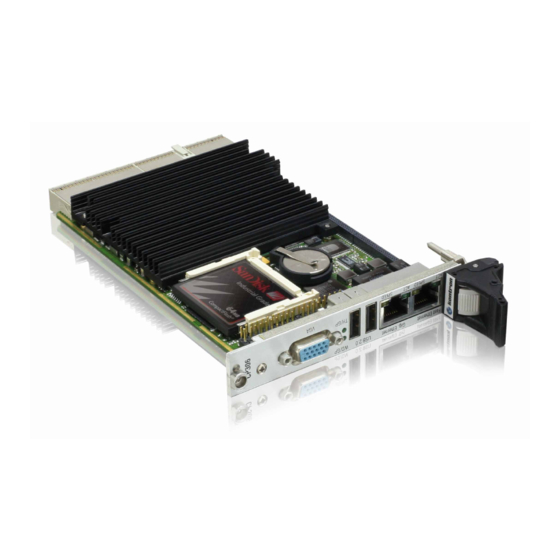
3U CompactPCI Pentium M Based CPU Board
Brand:
Kontron
| Category:
PCI Card
| Size: 1 MB
Table of Contents
Table of Contents
4
Introduction
26
Board Overview
27
Board-Specific Information
28
Optional Modules
29
CP306 Functional Block Diagram
30
System Relevant Information
29
Board Diagrams
30
CP306 4HP Front Panel
31
CP306 Board Layout (Front View)
32
CP306 Board Layout (Reverse View)
32
Board Layouts
32
CP306 4HP Version Main Specifications
33
Technical Specification
33
Kontron Software Support
37
Standards
38
Related Publications
39
2 Functional Description
42
Supported Intel® Pentium® M Processors on the CP306
43
Maximum Power Dissipation of Intel® Pentium® M (CPU Only)
43
Intel® Pentium® M Core Voltage in the Various Frequency Modes
43
Supported Intel® Celeron® M Processors on the CP306
44
Maximum Power Dissipation of Intel® Celeron® M (CPU Only)
44
Memory
44
855GME Chipset Functional Block Diagram
45
Graphics and Memory Controller Hub (855GME)
45
I/O Controller Hub ICH4
46
Battery
47
Smbus Device Addresses
48
EEPROM Address Map
48
Smbus Devices
48
Compactflash Socket Connector J8
49
FLASH Memory
49
Compactflash Connector J8 Pinout
50
PCI-To-PCI Bridge
50
Board Interfaces
51
Graphics Controller
52
USB Connectors J4 and J5
52
Partial List of Display Modes Supported
53
D-SUB CRT Connector J3
53
Video Resolution
53
CRT Connector J3 Pinout
54
COM Port Configuration Matrix
54
Universal Serial Ports (UART)
54
Dual Fast Ethernet Connector J6
55
Ethernet
55
RJ45 Connector J6-A Pinout
56
Fast Ethernet Controller J6-A
56
Pinouts of J6-B Based on the Implementation
57
Gigabit Ethernet
57
EIDE Interface
58
J7 (Secondary EIDE) Pinout
59
EIDE Interface Connector J7
59
Coding Key Colors
60
Compactpci Bus Interface
60
Compactpci Bus Connector J1 Pinout
61
Compactpci Connectors J1 and J2 Pinouts
61
Bit Compactpci Bus Connector J2 Pinout
62
Optional Rear I/O Interface on Compactpci Connector J2
63
Rear I/O Compactpci Bus Connector J2 Pinout
64
Optional Rear I/O Interface on Compactpci Connector J2
64
Rear I/O Configuration
66
Extension Connectors J10 and J11
67
I/O Extension Connector J10
67
Installation
70
CP306 Initial Installation Procedures
71
Standard Removal Procedures
72
USB Device Installation
73
Software Installation
74
Compactflash Configuration
78
Clearing BIOS CMOS Setup
78
Shorting Chassis GND (Shield) to Logic GND
78
Interrupt Setting
79
PCI Interrupt Routing
80
Memory Map for the 1St Megabyte
80
I/O Address Map
81
Special Registers Description
82
Watchdog Timer
83
Watchdog, Compactpci Interrupt Configuration Register
84
I/O Status Register
85
I/O Configuration Register
86
Board ID Register
87
Hardware Index Register
87
Logic Version Register
87
Board Version
87
LED Control Register
88
5 Phoenix BIOS
92
The Menu Bar
93
Main Menu - Screen Display
93
The Main Menu
93
The Legend Bar
94
The Field Help Window
95
Main Menu Selections
96
Master/Slave Sub-Menu - Screen Display
97
Master/Slave Sub-Menu Options
98
Advanced Menu - Screen Display
99
The Advanced Menu
99
Advanced Chipset Control Options
100
Advanced Chipset Control - Screen Display
100
PCI/PNP Configuration Options
101
PCI/PNP Configuration - Screen Display
101
PCI/PNP ISA IRQ Resource Exclusion Options
102
PCI/PNP ISA IRQ Resource Exclusion - Screen Display
102
Memory Cache - Screen Display
103
Memory Cache Configuration Options
104
I/O Device Configuration Menu 4 HP Version - Screen Display
105
I/O Device Configuration Options 4 HP Version
106
I/O Device Configuration Menu 8 HP Version - Screen Display
107
I/O Device Configuration Options 8 HP Version
108
Keyboard Features Options
110
Keyboard Features Menu - Screen Display
110
Miscellaneous Options
111
Miscellaneous Menu - Screen Display
111
Security Menu Options
112
Security Menu - Screen Display
112
The Security Menu
112
Power Menu Options
113
Power Menu - Screen Display
113
The Power Menu
113
Boot Menu - Screen Display
114
OEM Features Menu - Screen Display
116
OEM Features Options
117
Speedstep Frequency Table
118
PC Health - Screen Display
118
Watchdog Settings - Screen Display
119
Watchdog Settings Options
120
Temperature Management Options
121
Temperature Management - Screen Display
121
Front-Rear I/O Options
122
Front-Rear I/O - Screen Display
122
System Info Options
123
System Info - Screen Display
123
Exit Menu - Screen Display
124
The Exit Menu
124
Load Setup Defaults
125
Phoenixbios Messages
126
Phoenix Phlash16
131
Updating the Crisis Recovery Diskette
132
COM Ports Pinout
134
JRC Jumptec® Remote Control
134
POST Errors and Beep Codes
135
Checkpoint and Beep Codes
136
Absolute Maximum Ratings
144
DC Operational Input Voltage Ranges
144
6 Power Considerations
144
Backplane Requirements
145
Input Voltage Characteristics
146
Voltage Ramp of the CP3-SVE180 AC Power Supply
146
Rise Time Diagram
146
Supply Voltage Regulation
147
Power Consumption BIOS Pentium® M
148
Power Consumption Win 2000 IDLE Mode Pentium® M
148
Power Consumption Win 2000 100% CPU Usage Pentium® M
148
Power Consumption Win 2000 3D Mark Benchmark Pentium® M
148
Power Consumption Using Pentium® M and Real Applications
148
Power Consumption Win 2000 High Power Tool Pentium® M
149
Power Consumption Using Pentium® M and Testing Application
149
Power Consumption BIOS Celeron® M
150
Power Consumption Win 2000 IDLE Mode Celeron® M
150
Power Consumption Win 2000 100% CPU Usage Celeron® M
150
Power Consumption Win 2000 3D Mark Benchmark Celeron® M
150
Power Consumption Using Celeron® M and Real Applications
150
Power Consumption Win 2000 High Power Tool Celeron® M
151
Power Consumption Using Celeron® M and Testing Application
151
Power Consumption Table for CP306 Accessories
152
Start-Up Current of the CP306 with Pentium® M Processors
152
Start-Up Current of the CP306 with Celeron® M Processors
152
7 System Considerations
156
CPU External Thermal Supervision
157
Thermal Management Recommendations
158
Mobile Pentium® M Temperature Vs. Airspeed Graph
159
Forced Air Flow
159
Mobile Celeron® M Temperature Vs. Airspeed Graph
160
Peripherals
161
CP306-IDE1 Module Main Specifications
164
CP306IDE1 Module Functional Block Diagram
165
CP306-IDE1 Module Front Panel
166
CP306-IDE1 Module Layout (Front Side)
167
CP306-IDE1 Module Layout (Reverse Side)
167
Keyboard/Mouse Connector
168
A.6 Module Interfaces (Front Panel and Onboard)
168
Keyboard Connector CON6 Pinout
169
Serial Port Connectors CON2 and CON5 Pinouts
170
PC-Compatible D-SUB Serial Interface
170
A.6.2.2 Serial Port Configuration
171
Serial Port Configuration Diagram
171
PC-Compatible Parallel Interface Connector CON1
172
A.6.3.1 Parallel Port Connector CON1 Pinout
173
Pinout of the at 44-Pin Connector
176
A.6.4.1 Onboard EIDE Connector CON4 Pinout
176
Pinouts of EIDE Connectors CON3 and CON9
177
Floppy Drive Interface Connector CON7
178
A.6.5 Floppy Drive Interface
178
Floppy Drive Connector CON7 Pinout
179
I/O Extension Interface Connector CON10
180
Shorting Chassis GND (Shield) to Logic GND
181
Jumper Setting to Configure COM1
181
Jumper Setting to Configure COM2
181
A.7 Jumper Description
181
Jumper Settings for RS422 RXD Termination (COM1)
182
Jumper Settings for RS422 TXD and RS485 Termination (COM1)
182
Jumper Settings for RS422 RXD Termination (COM2)
182
Jumper Settings for RS422 TXD and RS485 Termination (COM2)
182
A.7.2.1 RS422 and RS485 COM1 Termination
182
B. CP-RIO3-03 Rear I/O
186
CP-RIO3-03 Front Panels, 4HP and 8HP Versions
187
B.2 Front Panels
187
CP-RIO3-03 Module Layout, 4HP Version
188
CP-RIO3-03 Module Layout, 8HP Version
188
B.3 Module Layout: 4HP and 8HP Versions
188
USB Connector CON3/CON4
189
B.4 Module Interfaces
189
VGA Connector CON6 Pinout
190
D-SUB VGA Connector
190
B.4.2 VGA Interface
190
RJ45 Connector CON2 Pinout
191
Ethernet/Fast Ethernet Connector
191
B.4.3 Fast Ethernet Interface
191
Serial Port Connectors CON8 and CON10 Pinouts
192
Fan Control Connector CON9 Pinout
192
Pinout of at Standard EIDE Connector CON7
193
Rear I/O Compactpci Bus Connector CON1 Pinout
194
B.4.7 Rear I/O Interface on Compact PCI Connector CON1
194
Shorting Chassis GND (Shield) to Logic GND
196
COM1 Configuration Using Jumper J3
196
COM2 Configuration Using Jumper J2
196
B.5 Jumper Setting
196
Advertisement
Advertisement
Related Products
Kontron CP3004-SA
Kontron CP3010-SA
Kontron CP307
Kontron CPS3105
Kontron CP6004-SA
Kontron CP6004-RC
Kontron CP6004X-SA
Kontron cPCI-MXP64GX
Kontron CP6004-RA
Kontron CP6-GPU8860
Kontron Categories
Computer Hardware
Motherboard
Server
Industrial PC
Desktop
More Kontron Manuals
Login
Sign In
OR
Sign in with Facebook
Sign in with Google
Upload manual
Upload from disk
Upload from URL