
Related Manuals for Metal-Fach SMART EKO


Summary of Contents for Metal-Fach SMART EKO
- Page 1 ENGLISH SMART EKO / SMART PLUS OPERATION AND MAINTENANCE DOCUMENTATION RANSLATION OF THE ORIGINAL MANUAL II 2019/06/01 SSUE...
- Page 2 Dear User, Thank you for choosing the heating boiler from Metal-Fach. We hope that the device will meet your requirements and bring much satisfaction. The heating boiler was designed and manufactured according to the most important, current norms and standards, guaranteeing safety and dependable use. Using the device in accordance with the provided manual ensures effective and dependable operation.
-
Page 3: Table Of Contents
Schematic 1.1 Serial plate ........................3 Connecting the boiler to the power supply ..............13 Schematic 7.1 Basic elements of the boiler SMART EKO, SMART PLUS ........5 Connecting the boiler to the chimney ................13 Schematic 8.1 Boiler dimentions SMART EKO, SMART PLUS ............6 Boiler start-up ........................ -
Page 4: Initial Activities
The Operation and Maintenance Documentation contains data concerning the design, installation and method of using SMART EKO, SMART PLUS series boilers with a retort burner. A thorough study of the manual enables a proper and safe operation of the boiler. -
Page 5: Boiler Equipment
The user should thoroughly read the instruction manual of the regulator, fan and feeder along as well as the burner. ATTENTION! METAL-FACH reserves the right to implement changes to the parametres, equipment and specification of the offered products without prior notice. -
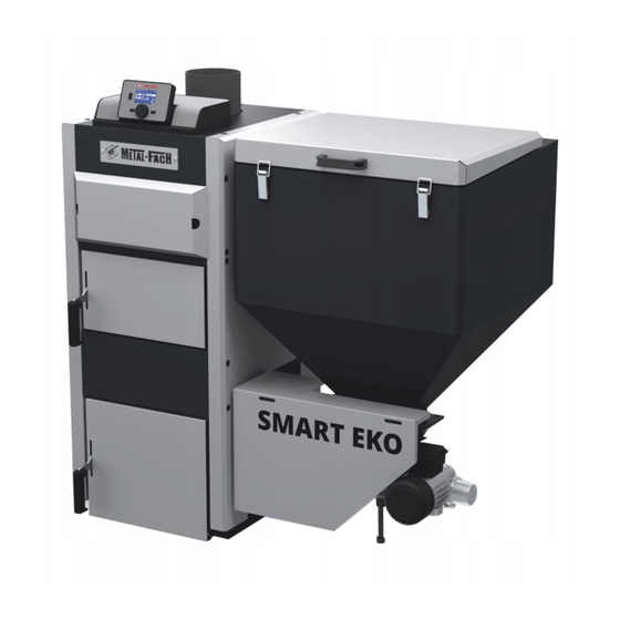
Page 6: Basic Elements Of The Boiler
The boiler is equipped with connector pipes: feed and return for boiler water with diameter G 1 Schematic 6.1 Basic elements of the boiler SMART EKO, SMART PLUS ½”, water drain pipe with diameter G ¾”, connector tube of regulator sensor and STB. A microprocessor-based regulator controls the boiler’s work and the combustion process. -
Page 7: Basic Dimentions Of The Boiler Smart Eko, Smart Plus
7. Basic dimentions of the boiler SMART EKO, SMART PLUS (USER/INSTALLER) Tab. 7.1 Boiler dimentions (mm) SMART EKO, SMART PLUS TYPE 12 kW 15 kW 20 kW 25 kW 30 kW 1250 1250 1250 1300 1300 1300 1300 1350 1350... -
Page 8: Technical Specifications Smart Eko, Smart Plus
8. Technical specifications SMART EKO, SMART PLUS (USER/INSTALLER) Tab. 8.1 Technical specifications SMART EKO, SMART PLUS TYPE OF BOILERS PARAMETERS UNIT 12 kW 15 kW 20 kW 25 kW 30 kW Nominal thermal output (coal) [kW] Boiler power range [kW]... -
Page 9: Control And Safety
9. Control and safety supply ventilation should be provided by an open slot of 200 cm2 in diameter and placed up to 100 cm over the floor surface. (USER/INSTALLER) the exhaust ventilation should be provided by an exhaust duct of 14 x 14 diameter and 1) Automatic control of the boiler can adjust: made from noncombustible material. -
Page 10: Boiler Installation
(USER/INSTALLER) law is amended. The important element of installation is correct setting and levelling of the SMART EKO, SMART PLUS boilers. The boilers do not require special base and need to be leveled with adjustable feet. The boiler must be set in the vertical position. -
Page 11: Tab. 13.1 Flammability Of Construction Products
13. Connecting the boiler to the heating The boiler must be placed on a flameproof pad that exceeds the boiler outline by 2 cm. if the boiler is located in the basement, it is recommended that it is placed on a base of at least 5 cm thick. system The bearing of the floor and the fire hazard conditions are the key elements of choosing the right location for the boiler i.e:... -
Page 12: Tab. 14.1 Symbols Applied In The Schematics
Schematic 13.2 Connecting boilers to the heating system diagram Schematic 13.1 Connecting the boiler to the heating system diagram Tab. 13.1 Symbols applied in the schematics Tab. 13.2 Symbols applied in the schematics Designation Designation Deaeration pipe Temperature sensor Expansion pipe Boiler temperature sensor Signal pipe Outside temperature sensor... -
Page 13: Schematic 14.3 Connecting The Boiler To The Heating System
Schematic 13.4 Connecting the boiler to the heating system with Laddomat and buffer Schematic 13.3 Connecting the boiler to the heating system Central heating pump (CO) Figure description: 10. Hot tap water pump (CWU) 1. Outside the building 11. Circulation pump 2. -
Page 14: Requirements For The Expansion Vessel
The fumes pipes should not be set in rooms where furnaces cannot be the manufacturer, holding a current Authorized Service Technician or Distributor certificate issued by METAL-FACH, or by a person holding an Electrician's license up installed, moreover, they cannot installed in walls and ceilings. Due to low fumes temperature, in order to protect the chimney from dampness and draught limit, use the acid- resistant or ceramic to 1.5 kW. -
Page 15: Boiler Start-Up
17. Boiler start-up Properly selecting the boiler to the heated rooms. Using, between the infeed and return of water, three- of four-way mixing valves, operated (USER/INSTALLER) manually or automatically. Maintaining the continuity of the burning process requires periodical replenishment of fuel in ATTENTION! the dispenser. -
Page 16: Boiler Maintenece And Cleaning
after the heating season is over, the boiler and the smoke duct must be thoroughly cleaned the boiler room should be kept tidy and dry ATTENTION! The boiler is not meant to be operated by persons of lowered mental or physical independence or by persons with no experience or limited knowledge about the product if they are not supervised or instructed by the person responsible for their safety. -
Page 17: Tab. 23.1 Spare Parts
20. Instruction for utilising the boiler 22. Possible faults and malfunctions (USER) (USER) Before scrapping the boiler, all the electronic elements should be removed. They should be Before calling the helpline read the FAQ section of the manual. disposed of according to the 2002/96/WE Electric and Electronic Equipment. In order to dispose of the electronic elements you should contact the manufacturer. - Page 18 Question Answer Explanation long boiler There is no simple answer. It can be assumed that the boiler The continuous burn time depends on: operate on full tank? can operate for 3-4 days. fuel calorific value, heating insulation of the building ...
- Page 19 Question Answer Explanation Is it allowed to fill up the Filling up the installation while the boiler is working is Letting water into the boiler runs the risk of unsealing the boiler and installation. If the boiler is overly heated installation with water while absolutely forbidden.
- Page 20 Question Answer Explanation The cleaning hatch seal is broken. Replace the seal. The seal between the burner and feeder pipe is broken. Tighten all the screws. Loose screws on the connections of the basket between the feeder and burner. What does The boiler overheats when the temperature exceeds 90 Cool down the boiler.
-
Page 22: Warranty Conditions
3. Presentation of the guarantee card, properly filled out (signed and sealed by the seller), at the Warranty conditions time of filing a claim, along with proof of the appliance's purchase (e.g. receipt, invoice). In the event of the User’s loss of the guarantee card, a duplicate will not be issued. 4. - Page 23 Claim procedure: 1. In the event where improper work of the appliance is detected, prior to filing a claim, make sure that all steps were taken according to the Operation and Maintenance Documentation. 2. The User should report the need to repair the appliance under the guarantee without delay, preferably within 7 days from the date on which the defect is detected.
-
Page 24: Confirmation Of Performance Of Inspection, Guarantee Repair, Maintenance Service
Confirmation of performance of inspection, guarantee repair, maintenance service: Item Contractor’s signature and seal Date of performance Description of performed activities... -
Page 26: Conformity Declaration We/Ue
Product name and intended use Solid fuel steel central heating boiler with automatic feeder. Type SMART PLUS, SMART EKO……………………………………. Manufacturer’s number …………………………………………….. Year of production 20……………………………………… Relevant documents: Act of 19 April 2016 on conformity assessment and market monitoring systems (Journal of Laws item 542). -
Page 28: Warranty Card For The Steel Boilers, Central Heating Water Boilers
Warranty Card for the steel boilers, central heating water boilers Power: ……………………………………….……………. [kW] Type: ……………………………………………………………. Number: ………………………………………………………………. Production date: ……………………………………….……………………………………….……………………………………….………………………………………………………………………………………………..………. Purchase date: ……………………………………….……………………………………….……………………………………….…………………………………………………………………………………………………..……... Buyer’s name: ………………………..……………………………………….……………………………………….……………………………………….………………………………………………………………………………… Address: ……………………………………….……………………………………….……………………………………….……………………………………….…………………………………………………………………… ………………………………………. ………………………………………. Date of purchase and seal I agree to the warranty conditions Buyer’s signature Personal data given in this form are processed by Jacek Kucharewicz, conducting economic activity under the company name Metal Fach Jacek Kucharewicz, 16-100 Sokółka, ul. -
Page 30: Warranty Claim
Warranty claim Client's details: ………………………………………………………………………………… Batch and product number: …………………………………….………………………… ………………………………………………………………………………….……………… ………………………………….………….……………………………………………… (first name, second name, address, contact number) Name of the product under warranty: ……………………………………………… Purchase document number: date: …………………………………………………………… …………………………………………………………………………………………………. Payment document number: ………..……….………………………………………………. Warranty period:: valid invalid Seller’s signature: …………………………………………………………………………... -
Page 32: Start-Up Report
The fan rotation is correct. Start-up report Opening the blower door with blow power. (Owner’s copy) The screw rotation is correct. In order to verify your purchase and warranty validity please send the report on the start-up within 30 days. You can do it by: 1. - Page 33 User's training certificate on Start-up date Boiler name Boiler power (kW) Serial number Comments ……………………….. ……………………….. ……………………….. ……………………….. Training on safe operation of the boiler is included in chapter 19. When operating ……………………………………………………. ……………………………………………………. the boiler you should remember (TECHNICIAN’S NAME) (OWNER’S NAME) Training boiler...
-
Page 34: Start-Up Report
The readings are in accordance with the Start-up report actual state. The fan rotation is correct. (METAL FACH Jacek Kucharewicz company's copy) Opening the blower door with blow power. In order to verify your purchase and warranty validity please send the report on the start-up within 30 days. - Page 35 User's training certificate on Start-up date Boiler name Boiler power (kW) Serial number Comments ……………………….. ……………………….. ……………………….. ……………………….. Training on safe operation of the boiler is included in chapter 19. When operating ……………………………………………………. ……………………………………………………. the boiler you should remember (TECHNICIAN’S NAME) (OWNER’S NAME) Training boiler...
- Page 38 METAL-FACH J ACEK UCHAREWICZ 66, 16-100 S IKORSKIEGO OKÓŁKA SERVICE INFOLINE . +48 85 711 94 54 METALFACH CALL US WRITE TO US +48 663 453 222 p.czepiel@metalfach.com.pl...
Need help?
Do you have a question about the SMART EKO and is the answer not in the manual?
Questions and answers