Advertisement
Table of Contents
- 1 Table of Contents
- 2 Boiler Equipment
- 3 Boiler Dimentions (MM) SD DUO
- 4 Boiler Dimentions (MM) SD DUO BIO
- 5 Boiler Technical Specifications SD DUO
- 6 Boiler Technical Specifications SD DUO BIO
- 7 Mass and Building Materials Flammability
- 8 Symbols Applied in the Schematics
- 9 Symbols Applied in the Schematics
- 10 Suggested Controler Settings for the Trough Burner
- 11 Suggested Controler Settings for the Feeder ECOENERGY
- 12 Spare Parts
- 13 Possible Faults and Malfunctions
- Download this manual
Advertisement
Table of Contents

Related Manuals for Metal-Fach SD DUO Series


Summary of Contents for Metal-Fach SD DUO Series
- Page 1 TRANSLATION OF THE ORIGINAL MANUAL ISSUE IV 09.2015 OPERATION AND MAINTENANCE DOCUMENTATION SD DUO / SD DUO BIO...
- Page 3 INTRODUCTION Dear User Thank you for choosing the heating boiler from Metal-Fach. We hope that the device will meet your requirements and bring much satisfaction. The heating boiler was designed and manufactured according to the most important, current norms and standards, guaranteeing safety and dependable use.
- Page 4 Initial activities (U)................ 19.9 Replacing the ignition (U/I)............Pictograms (U)................19.10 Disposal of trough burner after its lifespan (U)......Applied symbols (U/I)..............19.11 Possible trough operation diturbances (U)......... Definitions of terms in the manual (U/I).......... Warranty conditions (U)............. Certificate.................. General information (U)..............Boiler equipment (U)..............
-
Page 5: Table Of Contents
LIST OF TABLES DESCRIPTION OF SCHEMATICS Pictograms................... Serial plate................... Boiler equipment................Basic elements of the boiler SD DUO and SD DUO BIO....7.2.1 Boiler dimentions (mm) SD DUO..........7.2.1 Boiler dimentions SD DUO............7.2.2 Dimentions of the supplementary burning chamber and charging 7.2.2 Dimentions of the supplementary burning chamber and charging inlet SD DUO................ - Page 6 2. P 1. I (USER) (USER) Procedure to follow on delivery of the METAL-FACH boiler: Table 2.1 Pictograms check if the boiler is complete (tab 6.1 page 5) and if it has not been ź damaged during delivery confront your order with the data plate, that is placed on the left or ź...
-
Page 7: Boiler Equipment
-burner temperature information concerning the construction characteristics, installation and operation of boilers equipped with the SD DUO series Blower fan pcs. EKOENERGIA cast- iron retort burner and SD DUO BIO series trough burner. - Page 8 Every user should familirise themselves with the and 4 mm (for other elements) S235JR+N. operation manual for the regulator, blower fan and EKOENERGIA feeder. ATTENTION! METAL-FACH reserves the right to implement changes to the parametres, equipment and specification of the offered products without prior notice.
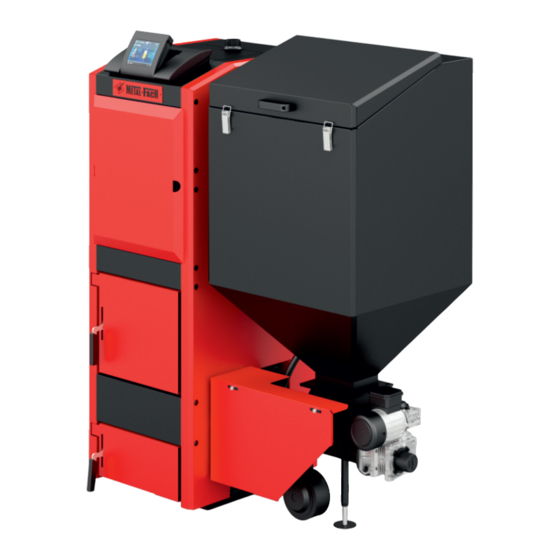
- Page 9 Description 7.1 Basic elements of the boiler SD DUO and SD DUO BIO Description 7.1 Basic elements of the boiler SD DUO and SD DUO BIO 16. Ventilator electrical connection Schematics description: 8. Ash door 17. Feeder electrical connection 1. Exchanger 9.
- Page 10 Description 7.1 Basic elements of the boiler SD DUO and SD DUO BIO Description 7.1 Basic elements of the boiler SD DUO and SD DUO BIO 21. Discharge stub with G3/4 int. 27. P3 additional pump socket 33. Central heating water 39.
- Page 11 7.2 B SD DUO (USER/INSTALLER) Description 7.2.1 Boiler dimentions SD DUO Description 7.2.1 Boiler dimentions SD DUO...
-
Page 12: Boiler Dimentions (Mm) Sd Duo
Table 7.2.1 Boiler dimentions (mm) SD DUO Type SD DUO-14 SD DUO-17 SD DUO-25 SD DUO-35 1230 1230 1230 1280 1680 1680 1680 1680 1430 1430 1430 1430 1717 1717 1717 1717 ATTENTION! ATTENTION! The manufacturer reserves the right to implement Maximum height of the any construction changes during modernisation boiler is 30 mm. - Page 13 7.3 B SD DUO BIO (USER/INSTALLER) Description 7.3.1 Boiler dimentions SD DUO BIO Description 7.3.1 Boiler dimentions SD DUO BIO...
-
Page 14: Boiler Dimentions (Mm) Sd Duo Bio
Table 7.3.1 Boiler dimentions (mm) SD DUO BIO Type SD DUO BIO-16 SD DUO BIO-20 SD DUO BIO-28 SD DUO BIO-34 1240 1240 1240 1290 1680 1680 1680 1680 1430 1430 1430 1430 1717 1717 1717 1717 ATTENTION! ATTENTION! The manufacturer reserves the right to implement Maximum height of the any construction changes during modernisation boiler is 30 mm. -
Page 15: Boiler Technical Specifications Sd Duo
7.4 T SD DUO SD DUO BIO (USER/INSTALLER) Table 7.4.1 Boiler technical specifications SD DUO Type of boiler Parameters Unit SD DUO - 14 SD DUO - 17 SD DUO - 25 SD DUO - 35 Nominal thermal output (coal) [kW] Heating surface [m ]... -
Page 16: Boiler Technical Specifications Sd Duo Bio
Table 7.4.2 Boiler technical specifications SD DUO BIO Type of boiler Parameters Unit SD DUO BIO - 16 SD DUO BIO - 20 SD DUO BIO - 28 SD DUO BIO - 34 Nominal thermal output (coal) [kW] Heating surface [m ] 2,33 2,62... - Page 17 7.5 C 6) Mixing valve acutator With this device you can adjust the set heating circle temperature in the central heating system, keeping the constant boiler temperature. (USER/INSTALLER) The temperature is calculated from the heating curve in relation to the outside temperature. 1) Automatic control of the boiler can adjust: boiler temperature ź...
- Page 18 8. R • the fuel and slag store should be located by the boiler room. The storing height up to 220 cm with a 50 cm free space above it. • the equipment for vertical and horizontal delivery of the fuel and slag should be considered.
-
Page 19: Mass And Building Materials Flammability
the SD DUO and SD DUO BIO boilers. the boilers do not require special base and need to be leveled with adjustable feet. the boiler must be set in the vertical position. The boiler must be placed on a flameproof pad that exceeds the boiler outline by 2 cm. - Page 20 1. Check that four adjustable feet 3. Place the feet into the have been provided dedicated slots 2. Level the boiler in relation to the floor (if the position of the 4. Level the position of the boiler boiler is level, there is no need for the feet) 8.2 C ATTENTION!
-
Page 21: Symbols Applied In The Schematics
ATTENTION! It is required that the boiler is connected to the heating installation by a four- way valve. ATTENTION! The temperature of the return water from the central heating boiler should not be lower than 45 C. The schematics of the connecting the boiler to the heating installation meet the PN- 91/B-02420 requirements. -
Page 22: Symbols Applied In The Schematics
Table 8.2.2 Symbols applied in the schematics Designation temperature sensor boiler temperature sensor outside temperature sensor hot tap water temperature sensor central heating temperature sensor return water temperature Description 8.2.2 Connecting boilers to the heating system digram Tpod feeder temperature sensor... - Page 23 Tpod Tpod Description 8.2.4 Connecting the boiler to the heating system with Description 8.2.3 Connecting the boiler to the heating system Laddomat and buffer...
- Page 24 Tpod Description 8.2.5 Connecting the boiler to a complex heating system with Laddomat and buffer Floor heating Figure description Central heating pump (CO) Outside the building Hot tap water pump (CWU) Expansion vessel Circulation pump Room regulator Additional pump P3 Mixer Block Heater...
- Page 25 The diameter of the deaeration and spill pipe should be at least ATTENTION! The start-up of the boiler should be carried out by the manufacturer- certified and trained company with a valid METAL-FACH Distributor or Service [mm] Technician Certificate. - Boiler efficiency [kW]...
- Page 26 LAMBDA SENSOR Shut off switches on the doors and covers LAMBDA MODULE PROTECTION FL 310 LG RTC (1xPOD) MODULE KEY: BLOWER ZO- open valve FEEDER ZZ- close valve CWU- hot tap water pump CO central heating pump ZP- ignition C/K- circulation pump or reserve boiler LZ- lambda sensor power supply DM- inlet fan ZTK- boiler thermal protection...
- Page 27 11. C materials. The smoke flues or their housings should meet the requirements set in the small chimneys fire test Polish Norm. It is allowed to build the housing from solid bricks of 12 cm thickness. The bricks should be set on the cement- plaster mortar with outer plaster or binder. The connections should be kept as short as possible and set in the upright (INSTALLER) direction to the chimney in order to avoid heat losses and additional...
- Page 28 ATTENTION Starting the boiler with fuel- wood The controller settings can be regulated • set the controller panel to „OFF” mode depending on the variety of the existing central • choose the kind of fuel to be used- wood heating systems, heating requirements of the •...
-
Page 29: Suggested Controler Settings For The Trough Burner
13. R Boiler power [kW] Pellet fuel Burner power Blower power Oxygen 100% 08.00 10.00 13.00 (USER) 14.00 17.00 To obtain the correct, fault-free and efficient operation of the boiler, the Motoreducer [1 rev/min] boiler should operate at 80% of its nominal power and temperature Feeding 100% 8,0 - 9,0s of 60 C. - Page 30 14. T Table 13.1.2 Suggested controler settings for the feeder ECOENERGY Boiler power [kW] Eco-pea coal (USER) Burner power Blower power Oxygen the boiler can be operated by two adults who have familiried ź 100% 13.50 themselves with the manual 14.10 the presence of unsupervised children in the boiler room, or allowing ź...
- Page 31 15. B 17. S (USER/INSTALLER) Table 17.1 Spare parts (USER) ATTENTION! Spare parts Article Clean the boiler only when it is disconnected from the power supply. Sensors Temperature sensors for FL300, FL310, FL600 Boiler sensor Feeder sensor In order to save fuel, the burner chamber as well as the convection Return sensor channels must be kept clean.
-
Page 32: Spare Parts
Table 17.1 Spare parts Instrumentation Capillary for fumes sensor Electric bundle Spare parts Article Ventilator, feeder, ignitor socket Rubber loop Feeder Motoreducer with engine 1 rpm Ewmar Power switch Motoreducer with engine 3 rpm Ewmar Fuse nest Motoreducer with engine 1 rpm Lenze Fuse Motoreducer with engine 3 rpm Lenze Interface transmitter... -
Page 33: Possible Faults And Malfunctions
Table 18.1 Possible faults and malfunctions Question Answer Explanation The continuous burn time depends on: -fuel calorific value -heating insulation of the building There is no simple answer. It can be assumed that the boiler -kind of installation i.e. floor heating, radiators, boiler How long can the boiler operate on full tank? can operate for 3-4 days. - Page 34 Table 18.1 Possible faults and malfunctions Question Answer Explanation In the first case, the wet fuel produces low fumes temperature causing fumes condensation. In such case, not only does the boiler get dirty but the chimney as well. In the second case, it is usually caused by insufficient amount of air in the combustion chamber.
- Page 35 Question Answer Explanation Letting water into the boiler runs the risk of unsealing the boiler and installation. If the boiler is overly heated it may unseal and crack. In the case of an oversized boiler, the temperature is reached very quickly making the boiler idle and the fumes gases burn out causing Is it allowed to fill up the installation with water Filling up the installation while the boiler is working...
- Page 36 Table 18.1 Possible faults and malfunctions Question Answer Explanation Mode 1- eco- pea. Mode 2- pellet as well as grain, seeds or fine wood chips of low What fuel can I use in boilers with a gutter You can use different fuels thanks to three working modes. granulation feeder? Mode 3- grate- wood and coal.
- Page 37 Question Answer Explanation Lower the feeding by 2-3% and check for improvement, if necessary, Why does the unburnt pellet fall into the ash repeat the procedure. Because the pellet feeing rate or ventilation are too big. tray? Lower the ventilation by 2-3% and check for improvement, if necessary, repeat the procedure.
- Page 38 Table 18.1 Possible faults and malfunctions Question Answer Explanation Heat the boiler above 80 C and keep this temperature for at least 6 hours. During the initial start-ups the boiler „sweats”. It is due to condensation. If necessary, repeat. Close the throttle on the flue. The chimney diameter is too big.
- Page 39 TROUGH BURNER...
- Page 40 Proper type and sort of fuel ensures: trouble- free operation of the multi-fuel burner ź higher burner performance and fuel saving of up 15% ź (USER/INSTALLER) lower emission of harmful chemicals into the atmosphere ź A complete fuel burner consists of: motoreducer ź...
- Page 41 Description 19.2.1 Trough burner schematics...
- Page 42 In the lower part of the boiler body is located a support foot which Table 19.2.1 Trough burner dimentions (mm) enables levelling of the feeder in the range of 2 cm. The multi-fuel burner Dimentions has an air chamber which serves as an expander for the air delivered by the blower, which is a part of the burner.
- Page 43 Description 19.2.2 Through burner dimentions (mm)
- Page 44 19.3 O 19.5 I (USER) The assembly and disassembly of the feeder and its elements should (USER/INSTALLER) not be forced. No pressure and vibrations are allowed and the whole unit should be carefully levelled. The connecting surfaces should be smooth The trough burner does not require any specialist operation.
- Page 45 3. Clean the element from any Protection element dirt and residues left by the (locking screw) locking screw 4. Insert a new protection element 1. Remove the plastic cover from the mechanism 5. Secure the screw with a nut 2. Remove the protection element from the motoreducer...
- Page 46 ATTENTION The settings must not be corrected more than 5-10% at a time in order not to spoil the correct settings. 19.7 F 6. The protection element has been installed correctly (USER/INSTALLER) The weekly activities that should be performed on the feeder: open the inspection door to check on the flame ź...
- Page 47 19.8 F (USER) You should periodically clean the feeder from dust, fuel remains or ash. Clean the engine chassis regularly. The reducers are filled with synthetic 2. Unscrew the lock nut. oil that ensures their performance during the operation period so you need to clean it on the outside.
- Page 48 19.11 P (USER) Table 19.11 Possible trough burner faults 5. Install the new ignition. Type of problem Possible cause Possible solution Check the power supply No power supply or the and the main switch boiler controller is off. of the controller. Check it and replace Motoreducer fuse is on.
- Page 49 Check if the feeder door is closed properly. The motoreducer Smoke coming The whole system Check the seals and Correct and ensure support is not properly from the bin. is leaky. feeder screws with stable connection. connected to the floor. burner.
- Page 50 6. Any damages due to incorrect use, improper storage, incompetent maintenance, non-conforming to the conditions outlined in this operation Metal-Fach Jacek Kucharewicz is not liable for an inappropriate and maintenance manual, and due to reasons outside the manufacturer's selection of boiler in relation to the heating surface. If the warranty call is...
- Page 51 21. C...
- Page 55 1. Manufacturer Metal-Fach Jacek Kucharewicz Ul. Sikorskiego 66 16-100 ka NIP 545-100-10-62 2. Product name and intended use. Solid fuel steel central heating boiler with automatic feeder. Type SD DUO/SD DUO BIO Manufacturer's number Year of production I. Relevant documents: 1.
- Page 56 Power Type: Number: Production date: Purchase date: Buyer's name: Address: Date of purchase and seal I agree to the warranty conditions Buyer's signature...
- Page 57 Client's details: Batch and product number: (first name, second name, address, contact number) Name of the product under warranty: Purchase document number date: Warranty period: valid invalid Payment document number: Detailed description of the fault Seller's signature: Warranty comencement conditions 1.
- Page 59 Purchaser's Copy ka, date ....…20..WARRANTY CLAIM NO. ……./R/20…… Client's details: Purchase document no.: ..................... First name and last name: ................... Full name of the purchased product: ................Address: ................................................... Phone no.: ........................Warranty expiry date: valid invalid Detailed description of the fault: .........................................................................................................
- Page 61 III. Connecting the components to the Valid Invalid Comments electrical system The conditions are in accordance with the Operation and Mainteneance Documentation in the chapter: 10. Connecting the components to the In order to verify your purchase and warranty validity please send the electrical system.
- Page 62 VI. The set parameters of the boiler parameters (chapter 13. Recommended settings of the boiler power) Boiler: System password: Boiler operation mode: Required temperature: Boiler hysthesis: Burner: Fuel: Stand-by maintaining: Operation maintaining: Blower outlet: Antilock: Test mode power: Feeding 100%: Initial stoking: Ignition: Blower+ Ignitor:...
- Page 63 III. Connecting the components to the Valid Invalid Comments electrical system The conditions are in accordance with (METAL FACH J the Operation and Mainteneance Documentation in the chapter: 10. Connecting the components to the In order to verify your purchase and warranty validity please send electrical system.
- Page 64 VI. The set parameters of the boiler parameters (chapter 13. Recommended settings of the boiler power) Boiler: System password: Boiler operation mode: Required temperature: Boiler hysthesis: Burner: Fuel: Stand-by maintaining: Operation maintaining: Blower outlet: Antilock: Test mode power: Feeding 100%: Initial stoking: Ignition: Blower+ Ignitor:...
- Page 68 METAL-FACH J TECHNIKA GRZEWCZA 16-100 . +48 85 711 94 54,...
Need help?
Do you have a question about the SD DUO Series and is the answer not in the manual?
Questions and answers
ошибка 00-00-63536