
Subscribe to Our Youtube Channel
Related Manuals for Metal-Fach Slim Pellet Series


Summary of Contents for Metal-Fach Slim Pellet Series
- Page 1 ENGLISH SLIM PELLET MINI/SLIM PELLET RANSLATION OF THE ORIGINAL MANUAL OPERATION AND MAINTENANCE DOCUMENTATION I 2018/11/09 SSUE...
- Page 2 Technical documentation of boilers: Boiler name Palnik SLIM PELLET; DW-X SLIM PELLET MINI; DW-X...
- Page 3 Dear User, Thank you for choosing the heating boiler from Metal-Fach. We hope that the device will meet your requirements and bring much satisfaction. The heating boiler was designed and manufactured according to the most important, current norms and standards, guaranteeing safety and dependable use. Using the device in accordance with the provided manual ensures effective and dependable operation.
-
Page 4: Table Of Contents
Table of Contents List of tables Initial activities ..........................4 Tab. 6.1 Boiler equipment ........................7 Applied symbols .......................... 4 Tab. 7.1 Boiler dimentions (mm) SLIM PELLET .................. 8 General information ........................4 Tab. 8.1 Technical specifications SLIM PELLET ................10 Use 4 Tab. -
Page 5: Initial Activities
confront your order with the data plate, that is placed on the left or right on the boiler body design, installation and method of using SLIM PELLET series boilers with a self-cleaning pellet read the user's manual carefully as it contains all the information required for safe operation burner. -
Page 6: Basic Elements Of The Boilers Slim Pellet And Slim Pellet Mini
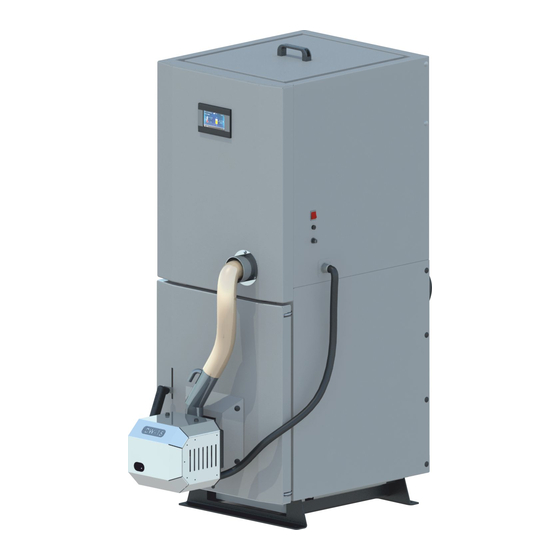
5. Basic elements of the boilers SLIM PELLET and SLIM PELLET MINI (USER/INSTALLER) SLIM PELLET and SLIM PELLET MINI are boilers with an automatic burner for biomass in the form of wood pellets. The boiler is made of attested P265GH steel sheets (furnace parts), S235JR steel sheets (parts of the water jacket) and heat-resistant steel (burner parts directly exposed to flame). -
Page 7: Schematic 5.2 Basic Elements Of The Boiler Slim Pellet Mini
Schematics description Exchanger 12. Ash drawer Self-cleaning pellet burner 13. Flexible fuel supply hose Fuel bin 14. Feeder Ash pan and furnace door 15. Controller display Flue cleaning hatch 16. Master switch Flue 17. Fuse Infeed stub 18. STB Return stub 19. -
Page 8: Boiler Equipment
The user should thoroughly read the instruction manual of the regulator, fan and feeder along as well as the self-cleaning pellet burner. ATTENTION! METAL-FACH reserves the right to implement changes to the parametres, equipment and specification of the offered products without prior notice. -
Page 9: Basic Dimentions Of The Boilers Slim Pellet And Slim Pellet Mini
7. Basic dimentions of the boilers SLIM PELLET and SLIM PELLET MINI (USER/INSTALLER) Tab. 7.1 Boiler dimentions (mm) SLIM PELLET SLIM PELLET 10 SLIM PELLET 15 SLIM PELLET 20 TYPE 1550 1550 1550 1510 1510 1510 1100 1100 1260 1470 1470 *This dimension does not account for the height of feet for leveling of the boiler. -
Page 10: Schematic 7.2 Boiler Dimentions Slim Pellet Mini
Tab. 7.2 Boiler dimentions (mm) SLIM PELLET MINI TYPE SLIM PELLET MINI 10 SLIM PELLET MINI 15 SLIM PELLET MINI 20 1220 1220 1320 1020 1020 1020 1370 1370 1370 1100 1100 1260 1470 1470 *This dimension does not account for the height of feet for leveling of the boiler. Schematic 7.2 Boiler dimentions SLIM PELLET MINI... -
Page 11: Technical Specifications Slim Pellet And Slim Pellet Mini
8. Technical specifications SLIM PELLET and SLIM PELLET MINI (USER/INSTALLER) Tab. 8.1 Technical specifications SLIM PELLET TYPE OF BOILERS PARAMETERS UNIT SLIM PELLET 10 SLIM PELLET 15 SLIM PELLET 20 Nominal thermal output [kW] Boiler power range [kW] 3-10 4,5-15 6-20 Heating surface Boiler water capacity... -
Page 12: Tab. 8.2 Technical Specifications Slim Pellet Mini
Tab. 8.2 Technical specifications SLIM PELLET MINI TYPE OF BOILERS PARAMETERS UNIT SLIM PELLET MINI 10 SLIM PELLET MINI 15 SLIM PELLET MINI 20 Nominal thermal output [kW] Boiler power range [kW] 3-10 4,5-15 6-20 Heating surface Boiler water capacity Maximum working pressure [bar] Maximum working temperature... -
Page 13: Control And Safety
9. Control and safety the height in a new building should be at least 220 cm. in old buildings the the boiler room should be at least 190 cm high as long as the ventilation inside is sufficient (supply- exhaust (USER/INSTALLER) ventilation) 1) Automatic control of the boiler can adjust:... -
Page 14: Boiler Installation
12. Boiler installation (USER/INSTALLER) The important element of installation is correct setting and levelling of the SLIM PELLET and SLIM PELLET MINI boilers. The boilers do not require special base and need to be leveled with adjustable feet. The boiler must be set in the vertical position. 1. -
Page 15: Connecting The Boiler To The Heating System
ATTENTION! 13. Connecting the boiler to the heating If the boiler is not levelled properly it can be damaged. system ATTENTION! The boiler must not be placed in a damp and wet room as the enhanced corrosion (INSTALLER) process will shortly damage the boiler. The connecting of the boiler to the central heating system should be contracted to a producer- certified company. -
Page 16: Schematic 13.1 Connecting The Boiler To The Heating System Diagram
Schematic 13.2 Connecting boilers to the heating system diagram Schematic 13.1 Connecting the boiler to the heating system diagram Tab. 13.2 Symbols applied in the schematics Tab. 13.1 Symbols applied in the schematics Designation Designation Temperature sensor Deaeration pipe Boiler temperature sensor Expansion pipe Outside temperature sensor Signal pipe... -
Page 17: Schematic 13.3 Connecting The Boiler To The Heating System
Schematic 13.4 Connecting the boiler to the heating system with Laddomat and buffer Schematic 13.3 Connecting the boiler to the heating system Figure description: Opis rysunku: 15. Central heating pump (CO) 1. Outside the building Na zewnątrz budynku 16. Hot tap water pump (CWU) 2. -
Page 18: Schematic 13.5 Diagram With Four-Way Valve Controlling Central Heating Circulations
Schematic 13.5 Diagram with four-way valve controlling central heating circulations Schematic 13.6 Diagram with two regulated heating circulations and with dispenser Descriptions 1. Boiler 9. Hot domestic water tank, Descriptions 2. Regulator 10. Hot tap water pump 1. Boiler 10. Temperature sensor of mixer circulation ct4, 3. -
Page 19: Connection Of Boiler To Heating Installation In Closed-Loop System
14. Connection of boiler to heating installation in closed-loop system (INSTALLER) When installing the boiler in the closed system, it is important to use elements that prevent overheating, excessive increase of pressure and use the controller of temperature during burning process. -
Page 20: Schematic 14.1 Safety Schematics Of The Boiler With The Cooling Coil And Thermal Protection
Protection of the installation by means of dual-function cooling valve. Thermal protection by means of cooling valve (e.g. DBV-2) serves to reduce water temperature in the heating installation when its temperature is exceeded. After safe temperature is exceeded, the valve opens. After the discharge valve opens, hot water flows out of the heating installation, and cold water can flow in from the supply pipe (water from the water supply network), cooling the boiler and installation. -
Page 21: Schematic 14. 3 Example Of Dbv2 Valve Connection To The Boiler's Supply
The solid fuel boilers with an automatic feeding feature carry very little risk of an uncontrolled rise in central heating temperature as the amount of the fed fuel is small. Moreover, in case of a sudden temperature rise, the safety procedure will activate without the user. If anything goes wrong, the controller will switch off the feeder for 30 sec in order to remove the ember. -
Page 22: Requirements For The Expansion Vessel
First start-up of the boiler must be performed solely by service personnel trained by the manufacturer, holding a current Authorized Service Technician or Distributor [MM] certificate issued by METAL-FACH, or by a person holding an Electrician's license up to 1.5 kW. - Boiler efficiency [kW]... -
Page 23: Schematic 16.1 Electrical Schematics For Connecting The Boiler- Controller Platinum
Schematic 16.1 Electrical schematics for connecting the boiler– controller PLATINUM. Electrical connection diagram of regulator: RT - control panel, and additionally, ecoSTER200/ecoSTER TOUCH room panel, λ - Lambda sensor module, B - module for support of additional heating circulations, BT – CT4 boiler temperature sensor, FS –... -
Page 24: Schematic 16.2 Electrical Schematics For Connecting The Boiler
Schematics of electric connections – additional B MODULE, where M3- regulated circuit temperature sensor (mixer 3) CT4 type M4- regulated circuit temperature sensor (mixer 4) CT4 type RM3- mixer 3 room thermostat RM4- mixer 4 room thermostat FS- BU feeder fuel level sensor H2- outlet to the back-up boiler control or alarm or hot tap water circulation pump Relay... -
Page 25: Connecting The Boiler To The Chimney
17. Connecting the boiler to the chimney 18. Boiler start-up (INSTALLER) (USER/INSTALLER) Smoke flue The flue pipes extract the fumes outside and intake air used for burning fuel. The necessary ATTENTION! draught depends on: The controller settings can be regulated depending on the variety of the existing ... -
Page 26: Tips When Using The Boiler
Maintaining the continuity of the burning process requires periodical replenishment of fuel in the dispenser. The frequency of replenishment depends on the intensity of the burning process and ATTENTION! should be determined individually based on experience. Replenishment is done every 1-3 days on The boiler is not meant to be operated by persons of lowered mental or physical average. -
Page 27: Spare Parts List
22. Spare parts list (USER/INSTALLER) Tab. 22.1 Spare parts Spare parts Article Sensors Boiler sensor Feeder sensor Hot Tap Water Sensor Controllers PLUM Regulator WPA 097 Fan Ignition Ignition 300W Sensor Lambda sensor set Lambda sensor case Feeder Fuel feeder worm, Dispenser feeder Instrumentation Rubber loop... - Page 28 Question Answer Explanation long boiler There is no simple answer. It can be assumed that the boiler The continuous burn time depends on: operate on full tank? can operate for 3-4 days. fuel calorific value heating insulation of the building ...
- Page 29 Question Answer Explanation The blower fan is not working? The blower fan is not working because it might be unplugged. Put the blower plug back in. After the boiler has cooled down, press the STB button. The boiler has overheated and STB protection has intervened. Is it allowed to fill up the Filling up the installation while the boiler is working is Letting water into the boiler runs the risk of unsealing the boiler and installation.
- Page 30 Question Answer Explanation What does alarm mean – Clean boiler means that the boiler's exchanger may be dirty. Clean the boiler's exchanger. excessive flue Flue gas temperature greater than 280 Reduce fuel feed temperature? Why does the unburnt pellet Because the pellet feeing rate or ventilation are too big. Lower the feeding by 2-3% and check for improvement, if necessary, repeat the procedure.
-
Page 31: Potential Problems With Pellas-Series Pellet Burner
24. Potential problems with PELLAS-series pellet burner Problems Causes The burner does not ignite fuel No fuel – check the dispenser and feeder for clogging Insufficient starting dose – check the starting dose Damaged igniter – check the heater ... - Page 32 The central heating pump isn’t working. Check: whether the boiler exceeded temperature above the central heating pump activation temperature – wait or reduce the value of this parameter. whether domestic hot water priority is active, blocking the central heating pump – deactivate the priority by setting domestic hot water pump work mode to No priority, ...
-
Page 33: Warranty Conditions
3. Presentation of the guarantee card, properly filled out (signed and sealed by the seller), at the time of filing a claim, along with proof of the appliance's purchase (e.g. receipt, invoice). In the Warranty conditions event of the User’s loss of the guarantee card, a duplicate will not be issued. 4. - Page 34 Claim procedure: 1. In the event where improper work of the appliance is detected, prior to filing a claim, make sure that all steps were taken according to the Operation and Maintenance Documentation. 2. The User should report the need to repair the appliance under the guarantee without delay, preferably within 7 days from the date on which the defect is detected.
-
Page 35: Confirmation Of Performance Of Inspection, Guarantee Repair, Maintenance Service
Confirmation of performance of inspection, guarantee repair, maintenance service: Item Contractor’s signature and seal Date of performance Description of performed activities... -
Page 38: Conformity Declaration We/Ue
Conformity declaration WE/UE Manufacturer: METAL-FACH Jacek Kucharewicz Ul. Sikorskiego 66 16-100 Sokółka NIP 545-100-10-62 Product name and intended use Solid fuel steel central heating boiler with automatic feeder. Type SLIM PELLET / SLIM PELLET MINI …………………………………….Manufacturer’s number…………………………………………….. Year of production 20………………………………………... -
Page 40: Warranty Card For The Steel Boilers, Central Heating Water Boilers
Warranty Card for the steel boilers, central heating water boilers Power: ……………………………………….……………. [kW] Type: ……………………………………………………………. Number: ………………………………………………………………. Production date: ……………………………………….……………………………………….……………………………………….………………………………………………………………………………………………..………. Purchase date: ……………………………………….……………………………………….……………………………………….…………………………………………………………………………………………………..……... Buyer’s name: ………………………..……………………………………….……………………………………….……………………………………….………………………………………………………………………………… Address: ……………………………………….……………………………………….……………………………………….……………………………………….…………………………………………………………………… ………………………………………. ………………………………………. Date of purchase and seal I agree to the warranty conditions Buyer’s signature Personal data given in this form are processed by Jacek Kucharewicz, conducting economic activity under the company name Metal Fach Jacek Kucharewicz, 16-100 Sokółka, ul. -
Page 42: Warranty Claim
Warranty claim Client's details: ………………………………………………………………………………… Batch and product number: …………………………………….………………………… ………………………………………………………………………………….……………… ………………………………….………….……………………………………………… (first name, second name, address, contact number) Name of the product under warranty: ……………………………………………… Purchase document number: date: …………………………………………………………… …………………………………………………………………………………………………. Payment document number: ………..……….………………………………………………. Warranty period:: valid invalid Seller’s signature: …………………………………………………………………………... -
Page 44: Start-Up Report
Start-up report The fan rotation is correct. (Owner’s copy) Opening the blower door with blow power. In order to verify your purchase and warranty validity please send the report on the start-up within 30 The screw rotation is correct. days. You can do it by: 1. - Page 45 Start-up date Boiler name Boiler power (kW) Serial number User's training certificate on Comments ……………………….. ……………………….. ……………………….. ……………………….. Training on safe operation of the boiler is included in chapter 19. When ……………………………………………………. ……………………………………………………. operating the boiler you should (TECHNICIAN’S NAME) (OWNER’S NAME) remember Training on boiler regulator and...
-
Page 46: Start-Up Report
The screw rotation is correct. 1. E-mail - w którym zostanie zamieszczony skan lub zdjęcie raportu. 2. List - w którym wysłana zostanie kopia raportu dla firmy METAL-FACH Jacek Kucharewicz, adres przedsiębiorstwa znajduje się na końcu Dokumentu Techniczno - Ruchowego. - Page 47 Start-up date Boiler name Boiler power (kW) Serial number User's training certificate on Comments ……………………….. ……………………….. ……………………….. ……………………….. Training on safe operation of the boiler is included in chapter 19. When ……………………………………………………. ……………………………………………………. operating the boiler you should (TECHNICIAN’S NAME) (OWNER’S NAME) remember Training on boiler regulator and...
- Page 50 METAL-FACH J ACEK UCHAREWICZ 66, 16-100 S IKORSKIEGO OKÓŁKA SERVICE INFOLINE . +48 85 711 94 54 METALFACH CALL US WRITE TO US +48 663 453 222 p.czepiel@metalfach.com.pl...
Need help?
Do you have a question about the Slim Pellet Series and is the answer not in the manual?
Questions and answers