Grundfos Control MPC Installation And Operating Instructions Manual
Hide thumbs
Also See for Control MPC:
Table of Contents
Advertisement
Advertisement
Table of Contents

Related Manuals for Grundfos Control MPC


Summary of Contents for Grundfos Control MPC
- Page 1 GRUNDFOS INSTRUCTIONS Control MPC Installation and operating instructions...
-
Page 2: Table Of Contents
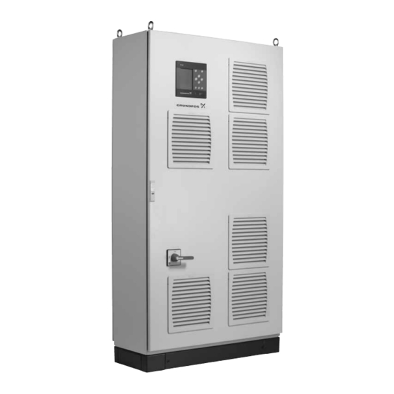
Grundfos Control MPC is used for control and monitoring of Warning booster systems and circulation systems. Prior to installation, read these installation and Control MPC consists of a control cabinet with a built-in controller, operating instructions. Installation and operation the CU 352. must comply with local regulations and accepted The control cabinet contains all necessary components such as codes of good practice. -
Page 3: Applications
3. Applications 4. Identification Control MPC is used for control and monitoring of pumps in these 4.1 Nameplate applications: The nameplate is fitted on the base frame. • booster systems • circulation systems for heating, cooling and air-conditioning. Type: 3.1 Pumps... -
Page 4: Software Label
Software label Pos. Description Control MPC - GSC file number Control MPC options - GSC file numbers Hydro MPC - GSC file number * Hydro MPC options - GSC file numbers * Pump data - GSC file numbers ** * Applies only to booster systems. -
Page 5: Type Key
Type range Control variants E: Pumps with integrated frequency converter (0.37 - 22 kW) EC: Pumps connected to a Grundfos CUE frequency converter - one per pump F: Pumps connected to one Grundfos CUE frequency converter S: Mains-operated pumps (start/stop) -
Page 6: Overview Of Control Variants
(cut-out pressure). parallel control of the pumps in operation. • A pump connected to the Grundfos CUE • Pump changeover is automatic and frequency converter always starts first. If • Pump changeover is automatic and... - Page 7 Control MPC Series 2000 Control MPC with three E-pumps. One E-pump in operation. Three E-pumps in operation. • Control MPC Series 2000 maintains a constant pressure through adjustment of the speed of the pumps connected. • The performance is adjusted to the...
-
Page 8: Installation
Indicator light, fault (red) 8. The system is now ready for operation. Brightness Grundfos can supply hydraulic data for CR, CRI, CRE and CRIE pumps where GSC files can be downloaded to the CU 352. Electrical data of power must be entered manually. -
Page 9: Control Panel
7.1 Display 7.2 Buttons and indicator lights The buttons (pos. 2 to 10 in fig. 4) on the CU 352 are active when they are lit. 7.2.1 Arrow to the right (pos. 2) Press [>] to go to the next menu in the menu structure. If you press [>] when menu "Settings"... -
Page 10: Functions
8. Functions 8.1 Tree of functions The functions depend on system configuration. Continued on page 11 1. Status 2. Operation 3. Alarm 1. Status 2. Operation 3. Alarm status Actual alarms Further settings 3.1 Actual alarms 3.1.1 Actual alarms 2.1.1 System operating mode 3.2 Alarm log System 2.1.2 Control mode... - Page 11 Continued from page 10 4. Settings Primary controller 4.1.1 PI controller 4.1.2 Alternative setpoints 4.1.2.1 Alternative setpoints 2 - 7 4.1.3 External setpoint influence 4.1.3.1 Input value to be influenced by 4.1.3.2 Setting of influence function 4.1.4 Primary sensor 4.1.6 Clock program 4.1.7 Proportional pressure...
- Page 12 8.2 Overview Section Display and display number See page 8.4 Status (1) 8.4.1 Actual alarms (3.1) 8.4.2 System (1.2) 8.4.3 Operating mode (1.2.1) 8.4.4 Setpoint (1.2.2) 8.4.5 Setpoint influence (1.2.3) 8.4.6 Measured values (1.2.4) 8.4.7 Analog inputs (1.2.5) 8.4.8 Log graph (1.2.6) 8.4.9 Battery status (1.2.7) 8.4.10...
- Page 13 Section Display and display number See page 8.7.31 Digital outputs (4.3.9) 8.7.32 Function of digital outputs (4.3.9.1 - 4.3.9.16) 8.7.33 Analog outputs (4.3.10) 8.7.34 Output signal (4.3.10.1 - 4.3.10.3) 8.7.35 Min., max. and user-defined duty (4.3.14) 8.7.36 Min. duty (4.3.14.1) 8.7.37 Max.
-
Page 14: Description Of Functions
8.3 Description of functions If a fault has occurred, the warning symbol The description of functions is based on the four main menus of alarm symbol will be shown in the line (C) Note the CU 352 control unit: together with the cause and fault code, for instance "Overtemperature (64)". - Page 15 8.4.2 System (1.2) 5. Stop – All pumps have been stopped. 6. Emergency run – The pumps run according to the setting made in display Emergency run (4.3.5). The performance required in these operating modes can be set in menu "Settings": •...
- Page 16 8.4.5 Setpoint influence (1.2.3) 8.4.7 Analog inputs (1.2.5) Fig. 11 Setpoint influence Fig. 13 Analog inputs Description Description The selected setpoint can be influenced by parameters. The This display shows an overview of the analog inputs and the parameters are shown as percentage from 0 to 100 % or as a measured values of each input.
- Page 17 8.4.9 Battery status (1.2.7) Besides information about the operating mode, it is possible to read various parameters in the status display, such as these: • actual operating mode • control source • speed (only 0 or 100 % are shown for mains-operated pumps) •...
-
Page 18: Operation (2
8.5 Operation (2) Select one of the settings below: • System operating mode In this menu, you can set the basic parameters, such as setpoint, (see section 8.5.2). operating mode, control mode and individual pump control. • Control mode 8.5.1 Operation (2) (see section 8.5.3). - Page 19 8.5.3 Control mode (2.1.2) Open loop In open-loop control, the pumps run at a fixed speed. The pump speed is calculated from the performance set by the user (0-100 %). The pump performance in percentage is proportional with the flow rate. Open-loop control is usually used when the system is controlled by an external controller which controls the performance via an external signal.
- Page 20 Setting via control panel Flow rate [m Proceed as follows to set an external control source to control the system: • Operation > Further settings > Control mode. • Select: Open loop. • Select: Stop x 2. Flow rate 2. Set to 100 %: Set setpoint 1, open loop. Pump 1 3.
- Page 21 8.5.4 Alternative setpoints (2.1.3) 8.5.5 Individual pump control (2.1.4) Fig. 27 Alternative setpoints Fig. 28 Individual pump control Description Description In addition to the primary setpoint 1 (shown in display 2 in menu It is possible to change the operating mode from automatic "Operation"), six alternative setpoints can be set for closed-loop operation to one of the manual operating modes.
- Page 22 8.5.6 Pump 1 - 6 (2.1.4.1 - 2.1.4.6) 8.5.7 Operation, pilot pump (2.1.4.7) Fig. 29 Pump 1 - 6 Fig. 30 Operation, pilot pump Description Description This display is shown for the individual pumps and makes it This display is only shown in systems that have been configured possible to set an operating mode.
- Page 23 8.5.8 Operation, backup pump (2.1.4.8) Fig. 31 Operation, backup pump Description This display is only shown in systems with a backup pump. It is possible to set the operating mode, start delay and stop limit for the pump. The function is only available in pressure-boosting applications. Setting range Auto It is possible to set a start delay.
-
Page 24: Settings (4
8.6 Alarm (3) This menu gives an overview of alarms and warnings. It is possible to reset alarms. 8.6.1 Alarm status (3) Man/ Water shortage auto Man/ Water shortage Stop auto Man/ Pressure high Stop auto Man/ auto Pressure low Man/ Stop auto... - Page 25 8.6.2 Actual alarms (3.1) 8.6.3 Alarm log (3.2) The alarm log can store up to 24 warnings and alarms. Fig. 33 Actual alarms Fig. 34 Alarm log Description This submenu shows the following: Description • Warnings caused by faults that still exist. Here warnings and alarms are shown.
- Page 26 8.7 Settings (4) 8.7.1 Primary controller (4.1) Fig. 37 Primary controller Fig. 36 Settings Description In this menu, you can set the following functions: It is possible to set the functions related to the primary controller. • Primary controller It is only necessary to make settings in this menu if the PI controller, Alternative setpoints, External setpoint influence, functionality is to be expanded with for instance alternative Primary sensor, Clock program, Proportional pressure,...
- Page 27 8.7.2 PI controller (4.1.1) PI controller settings for heating and cooling If another application than pressure boosting has been selected in the start-up wizard, the values of K and T will be set automatically according to the table below. As the system does not know the pipe length, the default parameters will be set according to the table to a pipe length (L or L...
- Page 28 8.7.3 Alternative setpoints (4.1.2) 8.7.4 Alternative setpoints 2 - 7 (4.1.2.1 - 4.1.2.7) Fig. 39 Alternative setpoints Fig. 40 Alternative setpoints 2 - 7 Description For each alternative setpoint, select the digital input to activate the setpoint. This function makes it possible to select up to six setpoints (2 to 7) as alternatives to the primary setpoint (1).
-
Page 29: Measuring Parameters
8.7.5 External setpoint influence (4.1.3) Setting via control panel • Settings > Primary controller > External setpoint influence > Input value to be influenced by. A list of available parameters appears. 1. Select the parameter which is to influence the setpoint. 3. - Page 30 8.7.6 Setting of influence function (4.1.3.2) Setting via control panel • Settings > Primary controller > External setpoint influence. 1. Set the influence function. 2. Set the number of points. 3. Set: External input value. (Point 1.) 4. Set as a percentage: Reduce setpoint to. (Point 1.) 5.
- Page 31 Setting via control panel Setting range • Settings > Primary controller > Primary sensor > Go to setting • Activation and setting of event. of analog input. Display Analog inputs (4.3.8) appears. 1. Select analog input (AI) for the primary sensor and set the parameters.
- Page 32 8.7.9 Proportional pressure (4.1.7) Factory setting The function is disabled. 8.7.10 S-system configuration (4.1.8) Fig. 47 Proportional pressure Description Fig. 49 S-system configuration The function can only be enabled in pressure-controlled systems and automatically adapts the setpoint to the actual flow rate to Description compensate for flow-dependent dynamic losses.
- Page 33 8.7.11 Setpoint ramp (4.1.9) 8.7.13 Min. time between start/stop (4.2.1) Fig. 53 Min. time between start/stop Fig. 51 Setpoint ramp Description Description This function ensures a delay between the starting/stopping of When this function is enabled, setpoint changes will be affected one pump and the starting/stopping of another pump.
- Page 34 Setting range 8.7.16 Forced pump changeover (4.2.4) 1 to 1000 starts per hour. Setting via control panel • Settings > Pump cascade control > Max. number of starts/ hour. 1. Set: • Min. time between start/stop. • Max. number of starts/hour. Factory setting MPC-E: 200 starts per hour...
- Page 35 8.7.17 Pump test run (4.2.5) 8.7.18 Pump stop attempt (4.2.7) Fig. 58 Pump stop attempt Fig. 57 Pump test run Description Description The function makes it possible to set automatic stop attempts of a This function is primarily used in situations where the forced pump when several pumps are running.
- Page 36 8.7.19 Pump start and stop speed (4.2.8) Setting via control panel • Settings > Pump cascade control > Pump start and stop Description speed. The function controls the starting and stopping of pumps. • Select: Use fixed speed. There are two options: •...
- Page 37 8.7.21 Compensation for pump start-up time (4.2.10) 8.7.22 Secondary functions (4.3) Fig. 62 Compensation for pump start-up time Fig. 63 Secondary functions Description Description The function is used for MPC-F systems only. Functions that are secondary in relation to the normal operation of the system can be set in this display.
- Page 38 The description of the stop function applies to all booster systems Diaphragm tank size with variable-speed pumps. MPC-S systems will have on/off control of all pumps as described in section Recommended diaphragm tank size [litres] 5. Overview of control Pump type variants.
- Page 39 3. Select one of the stop parameters. If you select "Customised System with flowmeter settings", you must set the parameters shown in fig. 68. Make the following additional settings: See the examples below. 1. Select: Go to setting of analog input. Display Analog inputs (4.3.8) appears.
- Page 40 Setting range 8.7.26 Digital inputs (4.3.7) • Pump speed • number of pumps • filling pressure • maximum filling time • warning or alarm + stop • ramp time for the pressure build-up phase. Setting via control panel • Settings > Secondary functions > Stop function > Soft pressure build-up.
- Page 41 8.7.27 Functions of digital inputs (4.3.7.1) Factory setting Digital input Function External start/stop. Open contact = stop. DI1 (CU 352) [10] Note: Input No 1 cannot be changed. Monitoring of water shortage (dry-running DI2 (CU 352) [12] protection). Open contact = water shortage (if the system is supplied with this option).
- Page 42 8.7.29 Analog inputs (4.3.8.1 to 4.3.8.7) 8.7.30 Analog inputs and measured value (4.3.8.1.1 - 4.3.8.7.1) Fig. 75 Analog inputs Fig. 76 Analog inputs and measured value Description Description Analog inputs can be set. Each display is divided into three parts: A function can be related to the individual analog inputs.
- Page 43 8.7.31 Digital outputs (4.3.9) 8.7.32 Function of digital outputs (4.3.9.1 - 4.3.9.16) Fig. 77 Digital outputs Fig. 78 Function of digital outputs Description Description Each digital output can be activated and related to a certain A function can be related to the individual outputs. function.
- Page 44 8.7.33 Analog outputs (4.3.10) • Ambient temperature • Differential pressure 2 - 3 • System power • Power, pump 1 - 6 • Power, pilot pump • Power, backup pump • Power, VFD • Speed, pump 1 - 6 • Current, pump 1 - 6 •...
- Page 45 8.7.36 Min. duty (4.3.14.1) 8.7.37 Max. duty (4.3.14.2) Fig. 82 Min. duty Fig. 83 Max. duty Description Description In all systems, apart from MPC-S systems, minimum duty is only The function makes it possible for a set number of pumps to run possible for variable-speed pumps.
- Page 46 Select and set: Note CRIE. • Number of pumps in operation, user-defined duty. For Grundfos E-pumps, the data of input power (P1) • Speed. must be entered. Factory setting The data are read by means of the pump performance curves The function is disabled as the following has been set: which can be found in WebCAPS on Grundfos’...
- Page 47 Setting via control panel • Settings > Secondary functions > Stop function Settings > Secondary functions > Stop function > Pump curve data. 4. Select and set: Duty point, Q0, • Rated flow rate Qnom 100 % speed • Rated head Hnom •...
- Page 48 8.7.41 Fixed inlet pressure (4.3.22) 8.7.42 Flow estimation (4.3.23) Fig. 91 Fixed inlet pressure Fig. 92 Flow estimation Description Description This function is only used when no inlet-pressure sensor is fitted As described in section (4.3.19), the 8.7.39 Pump curve data in the system and the inlet pressure is fixed and known.
- Page 49 8.7.43 Reduced operation (4.3.24) 8.7.44 Monitoring functions (4.4) Fig. 93 Reduced operation Fig. 94 Monitoring functions Description Description This function makes it possible to limit the number of pumps in The system has a series of functions that constantly monitor the operation, or for MPC-E systems, to limit power consumption.
- Page 50 Dry-running protection can take place by means of a pressure pumps run dry. Grundfos thus always recommends dry-running switch on the suction manifold or a level switch in a tank on the protection.
- Page 51 8.7.47 Measurement, inlet pressure (4.4.1.2) 8.7.48 Measurement, tank level (4.4.1.3) Fig. 97 Measurement, inlet pressure Fig. 98 Measurement, tank level Description Description Dry-running protection can take place by means of a pressure Dry-running protection can take place by means of a level transmitter measuring the inlet pressure.
- Page 52 8.7.49 Min. pressure (4.4.2) 8.7.50 Max. pressure (4.4.3) Fig. 99 Min. pressure Fig. 100Max. pressure Description Description The discharge pressure will be monitored if the application is The discharge pressure will be monitored if the application is pressure boosting. In all other applications, the system pressure pressure boosting.
- Page 53 8.7.51 External fault (4.4.4) Description With this function, the CU 352 can monitor set limits of analog values. It will react if the values exceed the limits. Each limit can be set as a maximum or minimum value. For each of the monitored values, a warning limit and an alarm limit must be defined.
- Page 54 8.7.53 Pumps outside duty range (4.4.7) 1: Solenoid valve opens. 2: Solenoid valve closes. 3: Solenoid valve opens. 4: Warning is activated. 5: Solenoid valve closes, P [bar] and warning is reset. Valve opening pressure Band Time [sec] Warning Valve opening pressure delay minus band Fig.
- Page 55 8.7.55 Log values (4.4.9) 8.7.56 Fault, primary sensor (4.4.10) Fig. 106Log values Fig. 107Fault, primary sensor Description Description Select the values to be logged and the number of samples per You can set how the system is to react if the primary sensor fails. hour.
- Page 56 8.7.57 Functions, CU 352 (4.5) 8.7.58 Display language (4.5.1) Fig. 108Functions, CU 352 Fig. 109Display language Description Description Make the basic settings of the CU 352 in this submenu. Here you select the language for the CU 352 display. CU 352 comes with most of these settings, or they are made at Setting range start-up and normally not to be changed.
- Page 57 8.7.59 Units (4.5.2) Set unit standard, measuring parameter and specific unit. See the example in fig. 111. Fig. 110Units Fig. 111 Example of selection of units Description Factory setting Here you can select units for the various parameters. The setting is done in the start-up wizard and depends on the Select between SI and imperial units.
- Page 58 If the clock is without voltage for more than 20 days, it must be If you have forgotten the password(s), contact set again. Note Grundfos. Setting range Setting via control panel The date can be set as day, month and year. The time can be set •...
- Page 59 CU 352. Furthermore, the version code and the product numbers See also section of configuration files (GSC) read into the unit are shown. It is also 8.8.1 Ethernet. possible to upgrade the software version. Contact Grundfos for 8.7.63 GENIbus number (4.5.6) further information. Fig. 115GENIbus number Description CU 352 can communicate with external units via an RS-485 interface (option).
- Page 60 If you want to use dynamic assignment, you must enable the function by selecting "Use DHCP" and clicking [ok]. A check mark Grundfos recommends that you protect the shows that the function has been enabled. connection to the CU 352 according to your safety...
- Page 61 See examples in fig. 117. For further information, contact Grundfos. The gateway may be a Grundfos CIU communication interface or a third-party gateway. For further information on the CIU, see WebCAPS, or contact Grundfos.
- Page 62 Not shown 0-100 % signal ** * The ambient temperature is typically the temperature in the room where the Control MPC is located. ** A 0-100 % signal from an external controller. It can for instance be a 0-10 V signal.
-
Page 63: Fault Finding
Repair or replace the cable. Power supply is disconnected. Connect the power supply. The system has stopped and CU 352 is defective. Contact Grundfos. cannot restart. Power supply is disconnected. Connect the power supply. Main switch is switched off. Switch on the main switch. -
Page 64: Technical Data
Lock the main switch with a padlock to ensure that the power supply cannot be accidentally switched on. Further information about Control MPC and pumps that can be controlled by the Control MPC is available in WebCAPS on 13. Technical data Grundfos’... - Page 65 My firma Grundfos prohlašujeme na svou plnou odpovědnost, že výrobky Wir, Grundfos, erklären in alleiniger Verantwortung, dass die Produkte Control MPC na které se toto prohlášení vztahuje, jsou v souladu s níže Control MPC auf die sich diese Erklärung beziehen, mit den folgenden uvedenými ustanoveními směrnice Rady pro sblížení...
- Page 66 Chúng tôi, Grundfos, tuyên bố trong phạm vi trách nhiệm duy nhất của Ne, Grundfos, deklarojmë vetëm nën përgjegjësinë tonë se produktet mình rằng sản phẩm Control MPC mà tuyên bố dưới đây có liên quan Control MPC me të cilat lidhet kjo deklaratë, janë në pajtueshmëri me tuân thủ...
- Page 67 GRUNDFOS Pumps (Hong Kong) Ltd. Telefax: +64-9-415 3250 Turkey «Порт» Unit 1, Ground floor GRUNDFOS POMPA San. ve Tic. Ltd. Sti. Norway Тел.: +7 (375 17) 286 39 72/73 Siu Wai Industrial Centre Gebze Organize Sanayi Bölgesi Факс: +7 (375 17) 286 39 71 29-33 Wing Hong Street &...
- Page 68 98288802 0516 ECM: 1184381 www.grundfos.com...
Need help?
Do you have a question about the Control MPC and is the answer not in the manual?
Questions and answers