
Related Manuals for DFI EC510-KH


Summary of Contents for DFI EC510-KH
- Page 1 EC510/511-KH User’s Manual Preliminary Version A55900944 Chapter 1 Introduction www.dfi.com...
-
Page 2: Fcc And Doc Statement On Class A
Product names or trademarks appearing in this manual are for identification purpose only and ance could void the user’s authority to operate the equipment. are the properties of the respective owners. Shielded interface cables must be used in order to comply with the emission limits. Chapter 1 Introduction www.dfi.com... -
Page 3: Table Of Contents
Installing a Mini PCIe Card ............. 14 Installing an M.2 Card ............15 Installing a PCI or PCIe Expansion Card ........16 Installing a CPU ..............17 Chapter 4 - Jumper Settings ......... 19 Clear CMOS Data ..............19 Chapter 1 Introduction www.dfi.com... -
Page 4: About This Manual
About this Manual Static Electricity Precautions An electronic file of this manual can be obtained from the DFI website at www.dfi.com. It is quite easy to inadvertently damage your PC, system board, components or devices even Todownload the user’s manual from our website, please go to “Support” > “Download Center.”... -
Page 5: Safety Precautions
• Disconnect the system from the DC outlet before cleaning. Use a damp cloth. Do not use liquid or spray detergents for cleaning. Chapter 1 Introduction www.dfi.com... -
Page 6: Chapter 1 - Introduction
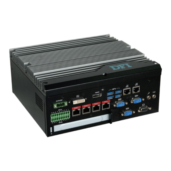
6 LAN ports (or 4 PoE + 2 LAN ports) 5 COM ports Display HDMI/DVI (DVI-D signal) HDMI or DP (DP available upon request) Front Panel 4 USB 3.0 & 2 USB 2.0 Type A ports 16-bit digital input/output Power 9~36V DC-in Rear Panel Chapter 1 Introduction www.dfi.com... -
Page 7: Specifications
Chapter 1 Specifications Expansion Processor 7th Generation Intel Core Processors, BGA1440 Socket • 1 x PCIe x16 (EC511-KH only) or 1 x PCI (EC510-KH only) ® ® ® • Intel Xeon Processor E3-1535M v6, Quad Core, 8M Cache, 3.1GHz • 1 x M.2 2280 M key (PCIe x4 NVMe, Intel optane memory support) (4.2GHz), 45W... -
Page 8: Getting To Know The Ec510/Ec511-Kh
DC 9~36V power input via a terminal block connector. Angled-corner Aligning side Align this edge with the Angled-corner left side of the connector (left) PCIe Expansion Slot (up) Provides PCIe or PCI expansion connectivity via a riser card. Chapter 1 Introduction www.dfi.com... -
Page 9: Mechanical Dimensions
Chapter 1 Mechanical Dimensions Chassis Dimensions Motherboard Dimensions 209.55 Rear View Gold finger PCIE X4 Gold finger PCIE X16 mini PCIe Left View Right View 235.00 Front View Chapter 1 Introduction www.dfi.com... -
Page 10: Chapter 2 - Getting Started
Refer to your operating system manual for instructions on installing the operating system. Installing the Drivers The system requires you to install drivers for some devices to operate properly. Refer to the Supported Software chapter for instructions on installing the drivers. Chapter 2 Getting Started www.dfi.com... -
Page 11: Chapter 3 - Installing The Devices
The 6 mounting screws on the left and right sides and bottom of the system are used to secure the cover to the chassis. Remove these screws and put them in a safe place for later use. Chassis screw Chassis screw Chassis screw Chapter 3 Installing the Devices www.dfi.com... -
Page 12: Installing A Sodimm
If you plan to install only one SODIMM, install it in the DIMM1 socket (lower one and farther from the center of the mainboard). The SODIMM sockets can only accept DDR4 memory modules. Please do not install other types of memory modules. Chapter 3 Installing the Devices www.dfi.com... -
Page 13: Installing A 2.5" Sata Drive
SATA cables Mounting screws SATA power connector Note: Connect SATA cables before affixing the SATA drive on the HDD bracket as the HDD bracket would prevent access to the SATA connectors of the drive. Chapter 3 Installing the Devices www.dfi.com... -
Page 14: Installing A Mini Pcie Card
2. Secure the card on the mainboard with the provided mounting screw. SIM 2 If the Mini PCIe card has antennas, route the antennas to the antenna holes on the front chassis of the device. Antenna holes Front bezel mounting screw Chapter 3 Installing the Devices www.dfi.com... -
Page 15: Installing An M.2 Card
Flip the cover up to open it Close the slot's cover and lock the slot by pushing the white latch outward. Mounting Screw Close the cover and lock it Chapter 3 Installing the Devices www.dfi.com... -
Page 16: Installing A Pci Or Pcie Expansion Card
Note: Slot plate Mounting screw and bracket The EC511-KH has one PCIe x16 slot with the H120-1E riser card, whereas the EC510- KH has one PCI slot with the H320-1P riser card. Chapter 3 Installing the Devices www.dfi.com... -
Page 17: Chapter 4 - Jumper Settings
2. Set the jumper pins 2 and 3 to On. Wait for a few seconds and set JP4 back to its default setting, pins 1 and 2 On. 3. Now plug the power cord and power on the system. Chapter 4 Jumper Settings www.dfi.com... -
Page 18: Com1/Com2 Rs232 Power Select
JP8 (for COM1) and JP7 (for COM2) are used to configure Serial COM ports to pure RS232 or RS232 with power. The pin functions (Pin1 and Pin 9) of COM1 and COM2 will vary according to JP8’s and JP7’s setting respectively. Chapter 4 Jumper Settings www.dfi.com... -
Page 19: Com1/Com2 Rs232/422/485 Select
You can also configure the RS485 auto flow mecha- must be set in accordance to JP16. nism through the BIOS setup utility. For more information, please refer to Chapter 7. Chapter 4 Jumper Settings www.dfi.com... -
Page 20: Com3/Com4 Rs232/422/485 Select
When COM3 RS232/422/485 is selected, JP12 and JP18 must be set in accor- RS232 (default) RS422 Full Duplex/RS485 dance to JP13. And when COM4 RS232/422/485 is selected, JP6 and JP19 must be set in accordance to JP5. Chapter 4 Jumper Settings www.dfi.com... -
Page 21: Dio High/Low Select (Dio 0~3)
2-3 Pull-down 2-3 Pull-down 1-2 Pull-up 1-2 Pull-up 5V/5V_Standby 5V/5V_Standby JP3 is used to set the digital pins 0~3 to pull-up or pull-down. JP2 is used to set the digital pins 4~7 to pull-up or pull-down. Chapter 4 Jumper Settings www.dfi.com... -
Page 22: Chapter 5 - Ports And Connectors
BIOS Setting • Two USB 2.0 ports Configure the onboard USB in the Advanced menu (“USB Configuration” submenu) of the • Two RS232/422/485 serial COM ports BIOS. Refer to Chapter 7 for more information. Chapter 5 Ports and Connectors www.dfi.com... -
Page 23: Com (Serial) Ports
You should feel resistance (due to a pin on the right) if the cable is not inserted correctly. For detailed instructions, see https://youtu.be/SUj07rfN5l8. Angled-corner Aligning side Align this edge with the Angled-corner left side of the connector (left) (up) Chapter 5 Ports and Connectors www.dfi.com... -
Page 24: Rj45 Lan Ports
Configure the display devices in the Advanced menu (“Video Configuration” submenu) of the BIOS. Refer to the Chapter 7 for more information. Driver Installation Install the graphics driver. Refer to Chapter 8 for more information. Chapter 5 Ports and Connectors www.dfi.com... -
Page 25: Usb Ports
3.0 ports at the rear panel and 2 USB 2.0 ports at the front panel of the system unit. damage to the system board. • BIOS Setting Configure the onboard USB in the Advanced menu (“USB Configuration” submenu) of the BIOS. Refer to Chapter 7 for more information. Chapter 5 Ports and Connectors www.dfi.com... -
Page 26: I/O Connectors
SATA drive’s power connector in order to provide power to the drive. BIOS Setting Configure the Serial ATA drives in the Advanced submenu (“SATA Configuration” section) of the BIOS. Refer to Chapter 7 for more information. Chapter 5 Ports and Connectors www.dfi.com... -
Page 27: Sata (Serial Ata) Power Connectors
SATA power connector and the other end to your storage device. multiple device bus that allows multiple chips to connect to the same bus and enable each one to act as a master by initiating data transfer. Chapter 5 Ports and Connectors www.dfi.com... -
Page 28: Rear Audio Connector
Mic-in Jack This jack is used to connect an external microphone. DIO 3 DIO 4 Driver Installation DIO 5 Install the audio driver. Refer to the Chapter 8 for more information. DIO 6 DIO 7 Chapter 5 Ports and Connectors www.dfi.com... -
Page 29: 12V Dc-Out
Max: 1.5A (18W) with 45W CPU HDD Power LED Power Please refer to "Specifications" in Chapter 1 for the system's processor list. HDD-LED Signal LED Power PWR-LED Ground Signal RST Signal Ground RESET SW ATX-SW N.C. Signal Chapter 5 Ports and Connectors www.dfi.com... -
Page 30: Expansion Slots
DPC_CTRL_CLK (N/A) LPC_AD3 PCI Express x4 Slot DPC_CTRL_DATA (N/A) LPC_LDRQ1# Reserved DPC_HPD (N/A) Install PCI Express cards such as network cards or other cards that comply to the PCI Ex- press specifications into this slot. Chapter 5 Ports and Connectors www.dfi.com... -
Page 31: Lpc Connector
The Low Pin Count Interface was defined by Intel Corporation to facilitate the industry’s transition ® SMB_CLK_RESUME DFI Board ID_0 towards legacy free systems. It allows the integration of low-bandwidth legacy I/O components SMB_DATA_RESUME DFI Board ID_1 within the system, which are typically provided by a Super I/O controller. Furthermore, it can be... -
Page 32: Lan Ports (Daughter Board)
Digital I/O Connector Pins DIO-A DIO-B PoE LED Speed LED LED Behavior Description LED Behavior Description DIO1 DIO1 The system is not 10Mbps connection DFI INC. powered on. MODEL: XCT3-4LPSEGD REV: SILK_TOP DIO2 DIO2 DATE: 08/22/2017 DFI INC. Green Supplying power over... -
Page 33: Chapter 6 - Mounting Options
The following illustration shows the location and dimension of the holes for mounting the device 1. The wall mounting holes are located on the bottom of the system unit. onto a wall or rack . Mounting hole Ø8.50 Ø3.60 251.80 262.80 Mounting hole Chapter 6 Mounting Options www.dfi.com... - Page 34 “Press DEL to run setup” will appear on the screen. If the message that field and press <Enter>. disappears before you respond, restart the system or press the “Reset” button. You may also restart the system by pressing the <Ctrl> <Alt> and <Del> keys simultaneously. Chapter 7 BIOS Setup www.dfi.com...
- Page 35 Minute displays minutes from 00 to 59. Second displays seconds from 00 to 59. System Date The date format is <month>, <date>, <year>. Month displays the month, from January to December. Date displays the date, from 1 to 31. Year displays the year, from 1980 to 2099. Chapter 7 BIOS Setup www.dfi.com...
- Page 36 Hyper-Threading Technology (HT) on the processor to improve per- ® formance of operating systems and software that are optimized for hyper-threading technology. Please check the software specifications to determine if enabling HT can be advantageous to the overall system performance. Chapter 7 BIOS Setup www.dfi.com...
- Page 37 PEG: PEG (PCIe Graphics devices connected to PEG lanes directly routed from the CPU) ->PCIe graphics devices->PCI graphics devices->IGFX (internal graphics) PCI: PCI graphics devices -> PCIe graphics devices->PEG (PCIe Graphics devices con- nected to PEG lanes directly routed from the CPU )->IGFX (internal graphics) Chapter 7 BIOS Setup www.dfi.com...
- Page 38 Select Serial ATA device speed from Gen1 (1.5 Gbit/s), Gen2 (3 Gbit/s), Gen 3 (6 Gbit/s) or auto. Enabled High-definition audio devices will be unconditionally enabled. Auto High-definition audio devices will be enabled if present and disabled otherwise. Chapter 7 BIOS Setup www.dfi.com...
- Page 39 UEFI Only Enable USB keyboard/mouse/storage support only under the UEFI environment. XHCI Hand-off Enable this function for operating systems that do not support xHCI Hand-off. The XHCI ownership change will be claimed by the XHCI driver. Chapter 7 BIOS Setup www.dfi.com...
- Page 40 Gen3 (8 GT/s). This option is only available for Mini PCIE1 and M.2. Hot Plug Enable or disable the hot plug function of the PCIe root port. This option is only avail- able for Mini PCIE1 and M.2. Chapter 7 BIOS Setup www.dfi.com...
- Page 41 Management Engine firmware flashing when updating the BIOS. ® Intel AMT Support Enable or disable Intel Active Management Technology BIOS extension. ® Un-Configure ME Clears all ME related configurations without requiring a password on the next boot. Chapter 7 BIOS Setup www.dfi.com...
- Page 42 Chapter 7 Debug Configuration This section configures the debug function. Dynamic EFI Debug Enable or disable output of the debugging messages through a serial port. Chapter 7 BIOS Setup www.dfi.com...
- Page 43 BIOS setup utility. you can select either the IPv4 or IPv6 network settings for UEFI network configuration. NIC Configuration Menu This screen shows hardware information for the Ethernet controllers and configures their operation. Chapter 7 BIOS Setup www.dfi.com...
- Page 44 . x . x . x (x must be a decimal value between 0 and 255). Local Gateway: Enter the gateway address in the IPv4 format. Local DNS (Domain Name System) Servers: Enter DNS (Domain Name System) server IP addresses in the IPv4 format. Chapter 7 BIOS Setup www.dfi.com...
- Page 45 The range of the temperature is from 0 to 127 Case Open Fan Speed Count 1 to Fan Speed Count 4 Enable or disable the case open function. Set the fan speed. The range is from 1 (lowest speed)-100% (full speed). Chapter 7 BIOS Setup www.dfi.com...
- Page 46 Chapter 7 PC Health Status This section displays PC health information such as the voltages and CPU and system temperatures. Chapter 7 BIOS Setup www.dfi.com...
- Page 47 Parity: None, Even or Odd. Stop bits: 1 bit or 2 bits. Flow control: None, RTS/CTS or XON/XOFF This is the global setting for all of the designated serial ports for the console redirection function. Chapter 7 BIOS Setup www.dfi.com...
- Page 48 If you select to set the supervisor password, this option will be shown. Enable or disable • Disable: Disable and deactivate TPM. prompt for password at boot. • Enable: Enable and activate TPM. Clear TPM Remove all TPM ownership contents. Chapter 7 BIOS Setup www.dfi.com...
- Page 49 Enable or disable the quiet boot function to configure the screen’s display between POST messages or the OEM logo at bootup. Select Disabled to display the POST messages and select Enabled to display the OEM logo. Chapter 7 BIOS Setup www.dfi.com...
- Page 50 DSF file extension and can be used for restoration. Restore Setting from file Select this option to restore BIOS configuration settings from a USB drive. Note that this option appears only if a USB device is detected on the system. Chapter 7 BIOS Setup www.dfi.com...
- Page 51 MAC address should be burned Initializing Current BIOS Model name: EC5xx-KH or not. New BIOS Model name: EC5xx-KH Current BIOS version: B19A.04A New BIOS version: B197.03A Updating Block at FFFFF000h 100% 100% C:\EC5xx-KH>_ Chapter 7 BIOS Setup www.dfi.com...
- Page 52 “Setup”. If your product package does not include a CD/DVD, you can download the latest drivers from the DFI Download Center: http://www.dfi.com/DownloadCenter Once you are on the Download Center page, select your product or type the model name and click "Search"...
- Page 53 Click “Next”. 4. Please wait while the instal- lation is in progress. 2. Read the license agreement, and then click “Yes”. 5. Click “Restart Now” to allow the new software installa- tion to take effect. Chapter 8 Supported Software www.dfi.com...
- Page 54 2. Read the license agree- 5. Click “Yes, I want to restart ment, and then click “Yes”. this computer now”, and then click “Finish”. Restarting the system will allow the new software installation to take effect. Chapter 8 Supported Software www.dfi.com...
- Page 55 “Finish”. 2. Click “I accept the terms in the license agreement” if you accept the agreement, and then click “Next”. 3. Select the program features you want to install, and then click “Next”. Chapter 8 Supported Software www.dfi.com...
- Page 56 ME) Driver, follow these steps: ® ® “Next.” 1. You are about to install the driver. Click “Next” to continue. 4. After the installation is complete, click “Finish”. 2. Read the license agree- ment, and then click “Next”. Chapter 8 Supported Software www.dfi.com...
- Page 57 “Finish”. Click “I accept the terms in the License Agreement” if you agree with Restart the system to allow the new the terms in the agreement and then software installation to take effect. click “Next”. Chapter 8 Supported Software www.dfi.com...
- Page 58 5. Setup is now installing the driver. 3. Read the file information and then click “Next”. 6. Click “Finish” to exit the setup. 4. Setup is ready to install the driver. Click “Next” to begin the installation. Chapter 8 Supported Software www.dfi.com...
- Page 59 SATA drives. It enables enhanced performance and power management for the storage subsystem. You can also install and set up Intel Optane™ memory with the Intel ® ® Rapid Storage Technology application. Chapter 8 Supported Software www.dfi.com...
- Page 60 1. Power on the system then press <Del> to enter the main menu of the BIOS. 2. Go to “Advanced” menu, and select the “SATA Configuration” menu. 3. Change the “SATA Mode Selection” to “Intel RST Premium” mode. 4. Save the changes in the “Exit” menu. 5. Reboot the system. Chapter 9 RAID www.dfi.com...
- Page 61 Select “OK” to continue. These steps are cited from the Intel Support site, “Set Up a System with Intel ® ® 3. The “Intel Rapid Storage Technology” menu appears. Enter this menu. Matrix RAID Technology” (Article ID: 000005789). ® Chapter 9 RAID www.dfi.com...
- Page 62 3. Setup is ready to install the utility. Click “Next” to continue. 4. Read the license agree- ment and click “I accept the terms in the License Agreement“ if you accept the agreement. Then, click “Next”. Chapter 9 RAID www.dfi.com...
- Page 63 “Finish”. “Next”. 6. Click “Next” to install to the default folder or click “change” to choose another destination folder. 7. Confirm the installation and click “Next”. Chapter 9 RAID www.dfi.com...
- Page 64 It protects the network from threats at the source by proactively blocking incoming threats, reactively containing infected clients before they impact the network, and proactively alerting when critical software agents are removed. 3. In the “Active Management Technology Support” menu, select “Enabled” for “Intel AMT Support”. Chapter 10 Intel AMT Settings www.dfi.com...
- Page 65 Copyright(C) 2003-16 Intel Corporation. All Rights Reserved MAIN MENU MEBx Login > Intel (R) ME General Settings > Intel (R) Small Business Technology Configuration MEBx Exit Intel(R) ME Password [↑↓] = Move Highlight [Enter] = Select Entry [Esc]= Exit Chapter 10 Intel AMT Settings www.dfi.com...
- Page 66 Copyright(C) 2003-16 Intel Corporation. All Rights Reserved MAIN MENU MEBx Login > Intel (R) ME General Settings > Intel (R) Small Business Technology Configuration MEBx Exit Intel(R) ME Password [↑↓] = Move Highlight [Enter] = Select Entry [Esc]= Exit Chapter 10 Intel AMT Settings www.dfi.com...
- Page 67 [Enter] = Select Entry [Esc]= Exit MAIN MENU MEBx Login > Intel (R) ME General Settings > Intel (R) Small Business Technology Configuration MEBx Exit Intel(R) ME Password [↑↓] =Move Highlight [Enter] =Select Entry [Esc] =Exit Chapter 10 Intel AMT Settings www.dfi.com...
- Page 68 Unconfigure Network Access <Full Unprovision> Disabled > Remote Setup And Configuration Enabled > Power Control [↑↓] = Move Highlight [Enter] = Select Entry [Esc]= Exit [↑↓] = Move Highlight [Enter] = Complete Entry [Esc]= Discard Changes Chapter 10 Intel AMT Settings www.dfi.com...
- Page 69 < Enabled> Storage Redirection <Enabled> KVM Feature Selection <Enabled> NONE Disabled Enabled [↑↓] = Move Highlight [Enter] = Complete Entry [Esc]= Discard Changes [↑↓] = Move Highlight [Enter] = Complete Entry [Esc]= Discard Changes Chapter 10 Intel AMT Settings www.dfi.com...
- Page 70 <Full Unprovision> > Remote Setup And Configuration > Power Control Default Password Only During Setup And Configuration Anytime [↑↓] =Move Highlight [Enter] =Select Entry [Esc] =Exit [↑↓] =Move Highlight <Enter> =Complete Entry [Esc] =Discard Changes Chapter 10 Intel AMT Settings www.dfi.com...
- Page 71 <Shared> Dynamic DNS Update <Disabled> Dynamic DNS Update <Disabled> Computer Domain Name Disabled Enabled [↑↓] =Move Highlight <Enter> =Complete Entry [Esc] =Discard Changes [↑↓] = Move Highlight [Enter] = Complete Entry [Esc]= Discard Changes Chapter 10 Intel AMT Settings www.dfi.com...
- Page 72 Unconfigure Network Access <Full Unprovision> Enabled > Remote Setup And Configuration > Power Control Full Unprovision [↑↓] =Move Highlight <Enter> =Complete Entry [Esc] =Discard Changes [↑↓] =Move Highlight <Enter> =Complete Entry [Esc] =Discard Changes Chapter 10 Intel AMT Settings www.dfi.com...
- Page 73 Provisioning Server FQDN > TLS PKI > RCFG > TLS PKI Provisioning server address Provisioning Mode: PKI [↑↓] = Move Highlight [Enter] = Select Entry [Esc]= Exit [↑↓] =Move Highlight [Enter] =Select Entry [Esc] =Exit Chapter 10 Intel AMT Settings www.dfi.com...
- Page 74 INTEL (R) REMOTE CONFIGURATION INTEL(R) REMOTE CONFIGURATION Remote Configuration** < Enabled> Start Configuration PKI DNS Suffix > Manage Hashes This will activate Remote Configura- Disabled tion. Continue: (Y/N) Enabled [↑↓] =Move Highlight [Enter] =Select Entry [Esc] =Exit Chapter 10 Intel AMT Settings www.dfi.com...
- Page 75 > Network Setup Activate Network Access Unconfigure Network Access <Full Unprovision> > Remote Setup And Configuration > Power Control [↑↓] =Move Highlight [Enter] =Select Entry [Esc] =Exit [↑↓] =Move Highlight [Enter] =Select Entry [Esc] =Exit Chapter 10 Intel AMT Settings www.dfi.com...
- Page 76 Intel (R) ME ON in Host Sleep States <Mobile: ON in S0, ME Wake in S3, S4-5 (AC only)> Idle Timeout 65535 Timeout Value (1-65535) 65535 [↑↓] =Move Highlight <Enter> =Complete Entry [Esc] =Discard Changes Chapter 10 Intel AMT Settings www.dfi.com...
Need help?
Do you have a question about the EC510-KH and is the answer not in the manual?
Questions and answers