Subscribe to Our Youtube Channel
Summary of Contents for Eaton COOPER POWER Cleer Series
- Page 1 COOPER POWER Loadbreak Apparatus Connectors SERIES Effective March 2016 MN650019EN Supersedes S600-100-1 March 2013 600 A 15, 25, and 28 kV class Cleer loadbreak connector system installation instructions...
- Page 2 CONTENTS OF THIS DOCUMENT SHALL NOT BECOME PART OF OR MODIFY ANY CONTRACT BETWEEN THE PARTIES. In no event will Eaton be responsible to the purchaser or user in contract, in tort (including negligence), strict liability or other- wise for any special, indirect, incidental or consequential damage or loss whatsoever, including but not limited to damage or...
-
Page 3: Table Of Contents
Contents SAFETY INFORMATION Safety information ................iv PRODUCT INFORMATION Introduction . -
Page 4: Safety Information
FOR LIFE FOR LIFE Eaton meets or exceeds all applicable industry standards relating to product safety in its Cooper Power™ series products. We actively promote safe practices in the use and maintenance of our products through our service literature, instructional training programs, and the continuous efforts of all Eaton employees involved in product design, manufacture, marketing, and service. -
Page 5: Product Information
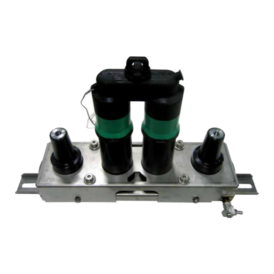
Introduction Eaton's Cooper Power series Cleer™ loadbreak connector system is a 600 A loadbreak device available in ratings for Additional information operation on 15, 25, and 28 kV class systems. It is used to... -
Page 6: Typical Configurations
Typical configurations In-line bracket configurations LOADBREAK CONNECTOR (LCN) BOL -T TERMINATION SOURCE LOAD Figure 2. 600 A loadbreak connector system with (2) BOL-T terminations. T-OP II OR BT-TAP BOL -T TERMINATION TERMINATION SOURCE LOAD Figure 3. 600 A loadbreak connector system with (1) BOL-T and (1) T-OP II or BT-TAP termination. Square bracket configurations LOADBREAK CONNECTOR (LCN) -
Page 7: Installation Instructions
Adjust the brackets for proper alignment and mark their location on the mounting surface. See Figure 7 . Eaton's 600 A loadbreak connector is designed to be operated in accordance with normal safe operating procedures. These instructions are not intended to... -
Page 8: Square Bracket Installation Instructions
Step 6 Square bracket installation instructions Step 1 Using supplied grounding clamps, connect bracket to system ground. Grounding clamp accommodates wire Using 1/2" hardware (customer supplied) mount assembly ranging from #8 sol to 2/0 str. to mounting surface or mounting plates of enclosure. See Figure 9. -
Page 9: Operating Instructions
Operating instructions WARNING WARNING High Voltage. Verify that BOTH arc followers are approximately 1-1/2" into the bushings. Failure to High Voltage. Cleer 600 A loadbreak bushings should comply could lead to a fault that may result in death or only be mated with other Cleer 600 A loadbreak serious injury. -
Page 10: Fault Close
Fault close It is not recommended that operations be made on known faults. If a fault is experienced, the connector and bushings must be replaced. Loadbreak operation Area must be clear of obstructions or contaminants that would interfere with this operation. Secure connector operating eye firmly onto clampstick and lock. -
Page 11: Cable Isolation And Grounding Instructions
LOAD Clean and lubricate apparatus Clean and lubricate interfaces of protective caps and Figure 13. Install 600 A loadbreak protective cap. standoff bushings using lubricant supplied or Eaton equivalent. Step 2 Install standoff bushing Attach a #14 AWG copper drain wire from the standoff bracket ground lug to system ground. - Page 12 Step 5 Step 7 Remove 200 A protective cap Re-install 200 A protective cap Using a clampstick, remove 200 A loadbreak protective cap After circuit has been verified as de-energized, using a from 200 A loadbreak reducing tap plug. See Figure 14. clampstick, re-install 200 A protective cap on loadbreak reducing tap plug.
- Page 13 Turn around and apply a force to the clampstick to push the elbow onto the bushing. A popping or snapping sound is often heard when this operation is performed. To check that the elbow is properly latched apply a gentle pull force to the clampstick.
-
Page 14: Visible Break And Visible Ground Using Bol -T Termination
LOAD Step 1 Clean and lubricate apparatus Clean and lubricate interfaces of protective caps and Figure 18. Remove "C" (LCN) connector. standoff bushings using lubricant supplied or Eaton equivalent. Step 4 Step 2 Install standoff bushing Install insulated protective cap... - Page 15 Step 5 Area must be clear of obstructions or contaminations that would interfere with the operation of the loadbreak elbow. Test Securely fasten a clampstick to the pulling eye of the Using an appropriate voltage sensing meter, test through grounding elbow. the load side 600 A loadbreak bushing interface to verify circuit is de-energized.
-
Page 16: Mounting Configurations And Dimensions
Mounting configurations and dimensions 26.88 682.8 20.08 5.00 4.00 101.6 16.27 413.3 8.93 226.8 2.04 51.8 4.64 117.9 14.4 18.1 CONFIGURATION - 3 20.0 20.0 CONFIGURATION - 2 21.9 25.6 CONFIGURATION - 1 Figure 22. In-line mounting configurations and dimensions. CLEER LOADBREAK CONNECTOR SYSTEM INSTALLATION INSTRUCTIONS MN650019EN March 2016... - Page 17 13.79 (350.3 mm) 12.79 (324.9 ) 10.21 10.21 (259.3 mm) (259.3 ) (127 ) 4.00 (101.6 mm) 15.30 (388.6 ) (76 ) 7.90 (200.7 ) 15.30 (388.6 mm) 7.90 3.55 (200.5 mm) (90.2 ) 10.5 3.55 (264 ) (90.2 mm) 11.5 (292 ) (38 )
- Page 18 This page intentionally left blank. CLEER LOADBREAK CONNECTOR SYSTEM INSTALLATION INSTRUCTIONS MN650019EN March 2016...
- Page 19 This page intentionally left blank. CLEER LOADBREAK CONNECTOR SYSTEM INSTALLATION INSTRUCTIONS MN650019EN March 2016...
- Page 20 Eaton.com/cooperpowerseries © 2016 Eaton All Rights Reserved Eaton is a registered trademark. Printed in USA For Eaton's Cooper Power series product Publication No. MN650019EN Rev 00 information call 1-877-277-4636 or visit: All trademarks are property www.eaton.com/cooperpowerseries. (Replaces S6001001 Rev 04)


Need help?
Do you have a question about the COOPER POWER Cleer Series and is the answer not in the manual?
Questions and answers