
Related Manuals for Eaton EZ II Series


Summary of Contents for Eaton EZ II Series
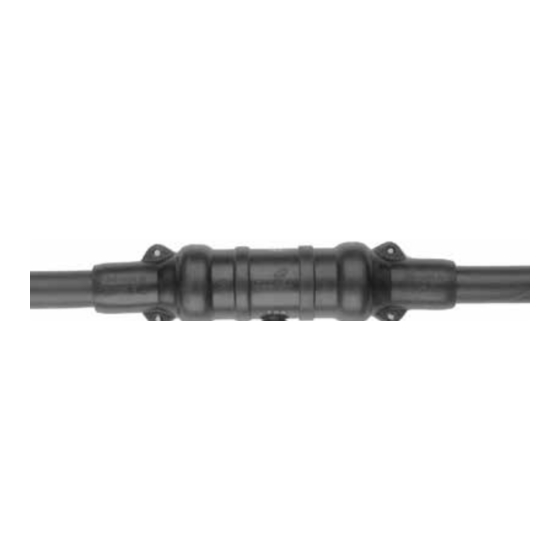
- Page 1 COOPER POWER Splices SERIES Effective January 2016 MN650007EN Supersedes April 2015 15 kV and 25 kV class EZ™ II splice installation instructions (For A, B, and C cable ranges only)
-
Page 2: Disclaimer Of Warranties And Limitation Of Liability
CONTENTS OF THIS DOCUMENT SHALL NOT BECOME PART OF OR MODIFY ANY CONTRACT BETWEEN THE PARTIES. In no event will Eaton be responsible to the purchaser or user in contract, in tort (including negligence), strict liability or other- wise for any special, indirect, incidental or consequential damage or loss whatsoever, including but not limited to damage or... -
Page 3: Safety Information
Contents SAFETY INFORMATION Safety Information ................iv PRODUCT INFORMATION Introduction . -
Page 4: Safety For Life
FOR LIFE FOR LIFE Eaton meets or exceeds all applicable industry standards relating to product safety in its Cooper Power™ series products. We actively promote safe practices in the use and maintenance of our products through our service literature, instructional training programs, and the continuous efforts of all Eaton employees involved in product design, manufacture, marketing, and service. -
Page 5: Product Information
After cables are prepared, the splice body is posi- Introduction tioned onto cable #1 of the prepared cables. Eaton manufacturers its Cooper Power™ series EZ II™ splice in accordance with the IEEE Std 404™-1993 standard The conductors are then crimped together with the supplied for cable joints. - Page 6 Preparation of cables to be spliced Step 3 Measure back from the end of both cables and remove 1-1/8" (29 mm) of the cable insulation, exposing the bare Step 1 conductor. Remove sharp edge of insulation by beveling at Overlap both cables. 45°...
- Page 7 Splice installation Step 5 Slide the splice body all the way on cable #1 until the bare conductor is exposed. (See Figure 5). Remove tape from Step 4 conductor of cable #1. Wire brush the conductor. If a cable rejacketing sleeve is used, slide it all the way on cable #1 and push it out of the way.
- Page 8 Step 6 Table 1. Measurement Guide Center the splice body over the compression connector, Compression Connector Compression Connector using the raised areas on the cable entrances of the splice body as indicators. (See Figure 6.) Run one of the neutral O.D.
- Page 9 This page is intentionally left blank. 15 KV AND 25 KV CLASS EZ II SPLICE INSTALLATION INSTRUCTIONS MN650007EN January 2016...
- Page 10 This page is intentionally left blank. 15 KV AND 25 KV CLASS EZ II SPLICE INSTALLATION INSTRUCTIONS MN650007EN January 2016...
- Page 11 This page is intentionally left blank. 15 KV AND 25 KV CLASS EZ II SPLICE INSTALLATION INSTRUCTIONS MN650007EN January 2016...
- Page 12 Eaton.com/cooperpowerseries © 2016 Eaton All Rights Reserved Eaton is a registered trademark. Printed in USA For Eaton's Cooper Power series product Publication No. MN650007EN Rev 01 All trademarks are property information call 1-877-277-4636 or visit: Supersedes 5000050839 Rev 03 of their respective owners.
Need help?
Do you have a question about the EZ II Series and is the answer not in the manual?
Questions and answers