
Related Manuals for Eaton 600 Ampere Deadbreak Junction 25 kV Class


Summary of Contents for Eaton 600 Ampere Deadbreak Junction 25 kV Class
- Page 1 COOPER POWER Junctions SERIES Effective May 2017 MN650044EN Supersedes January 1987 (S600-22-1) 600 Ampere Deadbreak Junction 15 & 25 kV and 35 kV Class Installation Instructions...
-
Page 2: Disclaimer Of Warranties And Limitation Of Liability
CONTENTS OF THIS DOCUMENT SHALL NOT BECOME PART OF OR MODIFY ANY CONTRACT BETWEEN THE PARTIES. In no event will Eaton be responsible to the purchaser or user in contract, in tort (including negligence), strict liability or otherwise for any special, indirect, incidental or consequential damage or loss whatsoever, including but not limited to... -
Page 3: Table Of Contents
Contents DISCLAIMER OF WARRANTIES AND LIMITATION OF LIABILITY . . . . . . . . . . . . . . . . . . . . . . . . . . . . . . . . . . . ii SAFETY FOR LIFE . -
Page 4: Safety For Life
FOR LIFE FOR LIFE Eaton meets or exceeds all applicable industry standards relating to product safety in its Cooper Power™ series products. We actively promote safe practices in the use and maintenance of our products through our service literature, instructional training programs, and the continuous efforts of all Eaton employees involved in product design, manufacture, marketing, and service. -
Page 5: Procedure
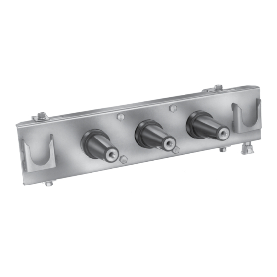
Eaton for specific recommendations. Install Mount the deadbreak junction solidly. The following tables provide mounting dimensions for an Eaton- supplied bracket. User-supplied mountings should be designed to prevent excessive stress while holding the junction firmly. - Page 6 600 Ampere Deadbreak Junction 15 & 25 kV and 35 kV Class Figure 2 . 15 kV and 25 kV class mounting Table 1 . 15 kV and 25 kV class mounting dimensions (in ./mm) Configuration 1 Configuration 2 Configuration 3 Number of Interfaces Min.
- Page 7 600 Ampere Deadbreak Junction 15 & 25 kV and 35 kV Class Figure 3 . 35 kV class mounting Table 2 . 35 kV class mounting dimensions (in ./mm) Number of Interfaces A 21.5 15.5 12.5 (546) (229) (394) (318) 27.5 15.0 21.5...
- Page 8 United States Eaton.com/cooperpowerseries © 2017 Eaton All Rights Reserved Eaton is a registered trademark. Printed in USA For Eaton‘s Cooper Power series product Publication No. MN650044EN information call 1-877-277-4636 or visit: All trademarks are property www.eaton.com/cooperpowerseries. May 2017 of their respective owners.
Need help?
Do you have a question about the 600 Ampere Deadbreak Junction 25 kV Class and is the answer not in the manual?
Questions and answers