
Summary of Contents for Marini Quarry Votager
- Page 1 MARINI QUARRIES GROUP S.R.L. Unipersonale Via Beura, 44 • 28844 Villadossola (VB) • ITALY Tel.: +39 0324 575106 • Fax: +39 0324 54096 Web : www.MariniQG.it E-mail: MariniQG@MariniQG.it...
- Page 2 “MARMO MACCHINE MARK”. Marini Quarries Group (*REGISTERED ON JUNE 25, 2008 UNDER APPLICATION NUMBER “MI2008C 007066” WITH THE PATENT OFFICE OF THE CHAMBER OF COMMERCE, INDUSTRY, CRAFT TRADE AND AGRICULTURE OF MILAN)
- Page 3 Cordially. Marini Quarries Group NOTE: The representation of the machine is NOTE: The representation of the machine is approximate and non binding, in that Marini approximate and non binding, in that Marini NOTE: The representation of the machine is NOTE: The representation of the machine is...
-
Page 4: Table Of Contents
TABLE OF CONTENTS INTRODUCTION Intended use of the machine Scope of this publication RESPONSIBILITIES GENERAL INFORMATION REGARDING DELIVERY Warranty Identification of the machine TECHNICAL DESCRIPTION QUARRY VOYAGER drilling unit POSITIONING for vertical drilling POSITIONING for horizontal drilling TECHNICAL CHARACTERISTICS Quarry Voyager Moving And Transport Rock drill MA90 Rotary head ID 160... - Page 5 A – KNOWING AND USING THE VOYAGER DRILLING UNIT: GENERAL WARNINGS SAFETY MEASURES FOR USE CHECKS BEFORE USE OPERATING INSTRUCTIONS HYDRAULIC POWER UNIT Hydraulic power unit – Gasoline engine Hydraulic power unit – Diesel engine Hydraulic power unit – Electric engine COMPRESSED AIR SUPPLY SYSTEM WATER SUPPLY FOR CORING IDCD CHECKS AND ADJUSTMENTS...
- Page 6 B – MAINTENANCE : MAINTENANCE OPERATIONS PROTECTING THE ENVIRONMENT SAFETY REGULATIONS FOR MAINTENANCE OPERATIONS INTERNAL-COMBUSTION ENGINE AND HYDRAULIC POWER UNIT PRESSURE REGULATIONS ON THE CONTROL PANELS HYDRAULIC POWER UNIT – GASOLINE END ELECTRIC ENGINE HYDRAULIC POWER UNIT – DIESEL ENGINE ADDING LUBRICATING OIL TO THE DRILLING UNIT PERIODIC CHECKS Daily...
-
Page 7: Introduction
This manual must not take the place of user experience but does provide all the information needed to correctly operate the machine. For additional copies or updates, contact the Marini Quarries Group who will provide information regarding this as well as how to resolve any problems. -
Page 8: Intended Use Of The Machine
Not observing the safety and operating regulations or using the machine when it is not in perfect working order can cause accidents that are prosecutable by law. Marini Quarries Group is not responsible for damage caused to people, objects or animals resulting from the incorrect use of the machine or from unauthorized structural modifications, applications or transformations. -
Page 9: General Information Regarding Delivery
The supplied machine is guaranteed against any manufacturing defects or faulty material for a period of 12 months from the date indicated on the shipping document. This warranty is contingent on the fact that any defects found must be communicated to Marini Quarries Group within 8 days of their occurrence. -
Page 10: Identification Of The Machine
Identification of the machine: The machine is identified by a serial number printed on the identification plate fixed to the frame. Furthermore, the engine, compressor and remote control have their own printed serial numbers. To ensure fast and efficient service, the main serial numbers should be entered in the table below. -
Page 11: Technical Description
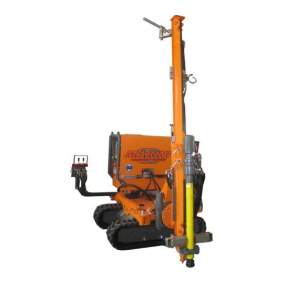
TECHNICAL DESCRIPTION QUARRY VOYAGER drilling unit: Figure 3 1. Self-moving carriage on tracks 2. Hydraulic power unit with electric motor/internal combustion engine 3. control panel for machine POSITIONING 4. WORK control panel (drilling) 5. hydraulic slide for the rock drill / rotary head 6. -
Page 12: Positioning For Vertical Drilling
The standard QUARRY VOYAGER drilling unit is composed of: Self-moving carriage on tracks CID 80 hydraulic drilling slide for the rock drill / rotary head Hydraulic power unit with internal-combustion engine Optional accessories: Coring, Rotary head ID160, MA90 Rock Drill, Hydraulic vice, Rod guide, Stabilizer, Drill steels, Threaded drifter rods, Drill steel sharpener, Handles and drill bits, Device for drilling in water, Dust collector. -
Page 13: Technical Characteristics
: 6 bar (max) DTH drilling and flushing air pressure : 10 bar (max) NOTE: All the data on this sheet is approximate and non binding, in that Marini Quarries reserves the right to make any modifications or changes without forewarning. -
Page 14: Moving And Transport
PRINT ON THE PLATE one 2300 QUARRIES GROUP MODEL 1100 Figure 7 SERIAL NUMBER DATE OF MANUFACTURING ATTACHMENT WEIGHT MAXIMUM OIL OPERATING PRESSURE MAXIMUM OIL FLOW RATE OIL TYPE Marini Marini Marini Marini Quarries Quarries Quarries Quarries Group Group Group Group... - Page 15 Rotopercussion Pneumatic Rock Drill MA90 TECHNICAL DATA Weight: 30kg Total length: 565 mm Sleeve bushing size: 22x108 mm (upon request 25x108 mm) Piston diameter: 90 mm Piston stroke: 50 mm. Max working pressure 6 bar Average air consumption at 6 bar: 4500 Litres/min (158 c.f.m.) with air vent Average air consumption at 6 bar: 4000 Litres/min (140 c.f.m.) with water drain...
-
Page 16: Safety
ID 160 Rotary head TECHNICAL DATA Weight Torque Rotation torque at 140 bar Working pressure 140∼160 Speed 40∼45 Threading of the output shaft API 2”3/8 F Figure 9 NOTE: The ID160 rotary head is interchangeable with the coring IDCD unit mounted on our hydraulic drilling slides. -
Page 17: General Information Regarding Safety
For certain risks, solutions could not be found from a design point of view. In these cases, the safety measures to be followed in order to operate as safely as possible are reported. CAUTION: Marini Quarries Group recommends that the instructions, procedures and recommendations provided in this manual be followed, that all the suggested precautions for good technique be adopted and that the current safety regulations be observed. -
Page 18: Safety Decals
Safety decals Safety decals and their locations: Figure (A) Figure (A) – Located on the frame of the drilling carriage: - Danger: Live electrical components. Risk of electrocution. - Danger: Crushing, shearing, vibrations, compressions, pounding, grinding, falling of material from above, noise during machine use. - Page 19 POS. 2 The machine is outfitted with certain safety devices that protect the user from incorrect maneuvers or in the case of emergency. Their locations and purposes: Drive wheels with normal braking (POS 1): The POS. 3 brake automatically releases both tracks when the carriage movement levers are moved.
- Page 20 Pressure switch and safety solenoid valve on the air line coming from the compressor: (Optional – available only with the machine equipped with MA90 rock drill) The safety solenoid valve (available on request) (G) on the air line allows the compressed air to pass if the line pressure is at least 2-3 bar.
-
Page 21: Noise Emission
The machine has two emergency buttons: one located on the work control panel (drilling) and the other on the control panel used for positioning (carriage movement). When either of these is pressed, all the machine actions are immediately stopped and the motor of the power unit shuts off. -
Page 22: Prevention Measures For The Machine Operators
The amount of noise produced by the QU QUARRY ARRY ARRY ARRY VOYAGER VOYAGER VOYAGER drilling unit depends on the rock VOYAGER drill mounted on the slide. The VOYAGER drilling unit equipped with the MA90 rock drill has a noise level of 102 102 dB Refer to the user’s manual for the hammer or the rotary head for more details. -
Page 23: General Warnings
A – Knowing and using the VOYAGER drilling and coring unit NOTE: The representation of the machine is approximate and non binding, in that Marini NOTE: The representation of the machine is approximate and non binding, in that Marini NOTE: The representation of the machine is approximate and non binding, in that Marini... - Page 24 CAUTION: The machine must only be used by competent and qualified personnel who have read this entire manual, regardless of their personal experience in this sector. CAUTION: Before beginning to use the machine or before making any especially complex or dangerous maneuvers, it is absolutely necessary that the work site be open and free of any obstacles.
-
Page 25: Checks Before Use
CHECKS BEFORE USE Before starting the machine: 1. Ensure that the machine is in perfect working order. For this, perform the following operational checks and controls in order to obtain improved productivity and also to meet all the safety regulations. CAUTION: IT IS FORBIDDEN TO BEGIN USING THIS MACHINE unless this manual has been read and completely understood. - Page 26 In case of emergency or malfunction, the QUARRY VOYAGER is fitted with a series of safety devices that stop the machine’s movements and simultaneously shuts down the motor of the hydraulic power unit. Figure 19 NOTE: the emergency board is installed inside the main control board on the unit equipped with electrical power pack The electronic control unit for managing the machine’s safety devices can be seen in Figure 19, which shows the following plugs connected:...
-
Page 27: Operating Instructions
OPERATING INSTRUCTIONS THE START-UP PROCEDURE MUST BE FOLLOWED TO BE ABLE TO SWITCH ON THE SELF-MOVING CARRIAGE. CAUTION: The machine must only be used by operators who are completely familiar with its operation. Any personnel who will be using the machine should therefore be properly trained. - Page 28 START-UP PROCEDURE 1. All the safety devices must be connected to the electronic control unit which manages the machine’s safety devices. (see pages 24 – figure 19). WORKING POSITIONING 2. POSITIONING / WORK switch: the switch installed at the drilling group translation end stroke controls the passing from POSITIONING to WORK.
-
Page 29: Hydraulic Power Unit
HYDRAULIC POWER UNIT Hydraulic power unit with inte Hydraulic power unit with internal Hydraulic power unit with inte Hydraulic power unit with inte rnal rnal- - - - combustion engine rnal combustion engine combustion engine combustion engine – – – – Gasoline (23 Hp) Gasoline (23 Hp) Gasoline (23 Hp) Gasoline (23 Hp) - Page 30 Hydraulic power unit with internal- - - - combustion engine Hydraulic power unit with internal combustion engine – – – – Diesel (23Hp) Diesel (23Hp) Hydraulic power unit with internal Hydraulic power unit with internal combustion engine combustion engine Diesel (23Hp) Diesel (23Hp) Ignition key Figure 28...
- Page 31 Bring the motor up to speed by moving the accelerator lever up. Figure 33 To turn off the motor, turn the key counterclockwise. Figure 34 After the work is completed and the power pack is turned off, turn the battery detach switch clockwise (OFF position). Figure 35 NOTE: NOTE:...
- Page 32 Hydraulic power unit with electric motor Hydraulic power unit with electric motor (12 Hp) (12 Hp) Hydraulic Hydraulic power unit with electric motor power unit with electric motor (12 Hp) (12 Hp) Make sure that the main switch (A A A A ) (Fig. 37) on the electrical panel is in position O O O O .
-
Page 33: Compressed Air Supply System
COMPRESSED AIR SUPPLY SYSTEM The control panel (Fig. 40) must be supplied at the WORK control panel following specifications: Pneumatic hammering for MA100: 4000/4500 lt/min 4000/4500 lt/min - - - - max 6 bar max 6 bar 4000/4500 lt/min 4000/4500 lt/min max 6 bar max 6 bar Pneumatic... - Page 34 ID CD CORING HEAD INSTALLATION To install the ID CD ID CD ( a ) ( a ) coring head the rotary head ID 160 ID 160 ( b ) ( b ) has to be removed : ID CD ID CD ( a ) ( a )
- Page 35 Connect the coring head water delivery hose A A A A to its connection B B B B on the control panel (fig. 41) Figura 41 The valve D D D D must be off. Connect the water delivery hose to the connection C C C C on the control panel . Water delivery : 20-25 l/min Open the valve D D D D to feed water to the coring head.
- Page 36 ACCESSORIES FOR CORING AND CORRECT POSITIONING 1 – Coupling 2 – Coring roads 3 – Core extractor (Attention : verify the correct sense of positioning) 4 – Extractor holder 5 – Diamond crown (core bit) 6 – Reaming 072010...
- Page 37 WORK CYCLE Important instructions for using the corer correctly 1) FIXING THE COLUMN 1) FIXING THE COLUMN 1) FIXING THE COLUMN 1) FIXING THE COLUMN Correct core drilling depends on the column being correctly fixed: the column must be absolutely and stably supported on the ground with its strut and rigidly anchored and held to it with the grooved pin and relative needle pin.
- Page 38 EXTENSION ROD JOINTING AND RECOVERING EXPLORER EQUIPPED WITH HYDRAULIC CLAMP ( O p t i o n a l ) ( O p t i o n a l ) ( O p t ( O p t i o n a l ) i o n a l ) An hydraulic clamp can be installed on the coring machine mod.
-
Page 39: Checks And Adjustments
Once got the right depth stop the down feed ( lever pos.1 in central position) and the head rotation (lever pos. 5 in central position). Start the head recovering : Close the hydraulic clamp by pushing forward the lever pos. 9 up to block the rod. Unscrew partially the rods form the coupling by the supplied wrench. - Page 40 CAUTION: For a new machine and after a long period of downtime, pour oil directly into the air supply tubes of the rock drill for faster initial lubrication. • Make sure that there is a sufficient amount of oil in the oil reservoir (A A A A ) (Fig.
-
Page 41: Positioning Controls
POSITIONING CONTROLS CAUTION: This machine POSITIONING designed to be safely positioned control panel used with maximum allowable tilt of 10% (~6°). POSITIONING control panel Figure 44 An emergency stop button (E) is found on the control panel used for positioning (fig. 45). Press the button (E) to stop the machine in an emergency. - Page 42 WARNING: before moving the machine incline forwards the drilling slide completely as shown in the drawing on right . Figure 48 CAUTION: To move the machine, position yourself with the control panel as shown in Figure 49, as far as possible from the tracks in order to avoid any operator interference with the equipment during positioning, especially with the tracks when moving.
-
Page 43: Stabilizer
STABILIZERS QUARRY VOYAGER is equipped with two stabilizers , on request , two extra stabilisers can be installed in the already available connecting points. Unscrew the bolts on pin A to remove the stabilizer. Screw them on the pin again once changed the stabilizers position. WARNING : the machine has to be stabilized before starting drilling to increase its stability. -
Page 44: Rotating The Drilling Unit
Rotation of the drilling unit For better positioning, the drilling unit can be rotated. 250° Figure 54 Extract the handwheel (A) from its transport position and insert it in the seat (B), then release the safety lever (C) (fig. 54). Turn the handwheel (fig. -
Page 45: Tilting The Column
Tilting the column The column can be tilted in order to align it with the desired drilling line. Figure 58 To tilt the column, move the lever shown in fig. 58. WORKING control panel Push the lever forward to tilt the column forward. Pull the lever back to tilt the column back. -
Page 46: Drilling On A Horizontal Plane
Drilling on a horizontal plane The column can be revolved in order to align it with the desired drilling line. Figure 61 WORKING control panel To revolve the column, move the lever shown in fig. 61. Push the lever forward to revolve the column to the right. Pull the lever back to revolve the column to the left. -
Page 47: Gallery Vault Drilling
Gallery vault drilling Fig. 64 It’s possible to perform drilling operations on gallery vaults. To use this work mode, the column must be repositioned on the roller bearing. 1) Position the column horizontally. 2) After the column is supported: Loosen the 8 fastening nuts on the roller bearing and the 2 on the feed cylinder (fig. -
Page 48: Anchoring The Column With Chains
ANCHORING THE COLUMN WITH CHAINS (OPTIONAL for DTH DRILLING / MANDATORY for CORING ) Figure 66 1. Chain fastening rings. 2. Hooks (shackles) 3. Column 4. Chains 5. Turnbuckle 6. Pin 7. Peg 1. Make 3 x 34mm holes at a depth of 20 cm (8 inches). 2. -
Page 49: Work Commands
WORK COMMANDS WORK POSITIONING control panel control panel WARNING: start drilling only after having efficiently stabilized the slide. Figure 67 An emergency stop button (E) is found on the WORK control panel (fig.68). Press the button (E) to stop the machine in an emergency. When pressed, the button remains in this position. -
Page 50: Drilling
DRILLING: Before drilling, make sure that the column is securely resting on the drilling surface (see “Moving the column closer”). Open the valve (F) to feed the rock drill flushing and the valve WORK control panel (A) to feed the rock drill percussion. NOTE: the gauge indicator (B) has to stay on gree area (6 bar). -
Page 51: Hydraulic Vice
Hydraulic vice : (optional) (fig. 74) Closing the hydraulic vice: pull the lever (fig. 75). Opening the hydraulic vice: push the lever (fig.75). WORK control panel Fig. 74 Fig. 75 Control panel with air and water flushing: (optional) (fig.76) WORK control panel AIR line WATER WATER line... -
Page 52: B - Maintenance
B – Maintenance NOTE: The representation of the machine is approximate and non binding, in that Marini NOTE: The representation of the machine is approximate and non binding, in that Marini NOTE: The representation of the machine is approximate and non binding, in that Marini... -
Page 53: Maintenance Operations
MAINTENANCE OPERATIONS CAUTION: The maintenance and repair operations must be done in authorized workshops and by qualified personnel. The operator must only perform the checks and maintenance operations described in this manual. These operations must be done respecting the safety regulations as described in this manual. - Page 54 SAFETY REGULATIONS DURING MAINTENANCE OPERATIONS CAUTION: When changing the oil, it is important the fundamentals of personal hygiene be followed. Wear protective garments, overalls, PVC gloves, etc. When finished changing the oil, wash any skin that has come in contact with the dirty oil with soap and water.
-
Page 55: Pressure Regulations On The Control Panels
CAUTION: All the pressures have been factory set. The modification of these settings must be done by a professional and following the indications provided by the technical service department. Marini Quarries Group cannot be held responsible for the incorrect operation of the machine resulting from arbitrary and unauthorized interventions. - Page 56 072010...
-
Page 57: Hydraulic Power Unit - Gasoline End Electric Engine
Hydraulic power unit – – – – Gasolin Hydraulic power unit Gasoline e e e and electric engine and electric engine Hydraulic power unit Hydraulic power unit Gasolin Gasolin and electric engine and electric engine Check the hydraulic fluid level in the power unit every day. The indicator (A) shows the temperature of the oil and the amount in the reservoir. - Page 58 Hydraulic power unit – – – – Diesel Hydraulic power unit Diesel engine engine Hydraulic power unit Hydraulic power unit Diesel Diesel engine engine Attention: The checks of the oil and fuel level or any top-ups must be completed with the engine stopped and the hydraulic power pack supported on a flat surface.
-
Page 59: Periodic Checks
Adding lubricating oil to the rock drill ll ll ll Adding lubricating oil to the rock dri Adding lubricating oil to the rock dri Adding lubricating oil to the rock dri CAUTION: Before adding oil, stop the machine and close the supply of compressed air and release the air in the control panel;... -
Page 60: Troubleshooting Guide
(page 25) Breakdown of the safety device Contact the Marini Quarries Group control unit (*) customer service department Breakdown of the motor of the Contact the Marini Quarries Group hydraulic power unit. - Page 61 The motor suddenly shuts restarting the work. Irregular operating pressure Check the air and oil operating pressures Contact the Marini Quarries Group Hydraulic pump breakdown (*) customer service department Breakdown of the motor of the Contact the Marini Quarries Group hydraulic power unit.
- Page 62 EMERGENCY ELECTRICAL DIAGRAM GASOLINE MOTOR VERSION 072010...
- Page 63 EMERGENCY ELECTRICAL DIAGRAM DIESEL MOTOR VERSION 072010...
- Page 64 ELECTRICAL DIAGRAM ELECTRICAL MOTOR VERSION 072010...
-
Page 65: Rope Switch Adjustment
ROPE SWITCH ADJUSTMENT 072010... - Page 66 HYDRAULIC DIAGRAM 072010...
- Page 67 NOTE 072010...
Need help?
Do you have a question about the Quarry Votager and is the answer not in the manual?
Questions and answers