
Related Manuals for Harmonic Drive RSF Series


Summary of Contents for Harmonic Drive RSF Series
- Page 1 R S F S u p e r mini A ct uat or RSF Brushless Servo Actuator Total Motion Control P r e c i s i o n G e a r i n g & M o t i o n C o n t r o l...
- Page 2 SAFETY GUIDE For actuators, motors, control units and drivers manufactured by Harmonic Drive LLC Read this manual thoroughly before designing the application, installation, maintenance or inspection of the actuator. Indicates a potentially hazardous situation, Indicates a potentially hazardous situation, which, if...
-
Page 3: Table Of Contents
RSF supermini series AC servo actuator manual Contents Chapter 1 Overview of the RSF supermini series ................... 1 Major characteristics........................1 Ordering information ........................2 Combinations with drivers ......................2 Specifications of RSF supermini actuators ................. 3 External dimensions of actuators ....................4 One-way positioning accuracy.................... - Page 4 RSF supermini series AC servo actuator manual Location and installation ......................25 3-3-1 Environment of location ....................25 3-3-2 Considerations into External Noise ................25 3-3-2 Installation........................26 Chapter 4 Motor shaft retention brake(RSF-5A) ................... 27 Motor shaft retention brake specifications ................27 Controlling the brake power supply ..................
-
Page 5: Chapter 1 Overview Of The Rsf Supermini Series
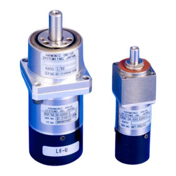
The RSF supermini series are ultra-small AC servo actuators combining ultra-precision control deceleration device Harmonic Drive® that provides precision rotation operation at a high torque with ultra-small AC servo motor developed to make use of the performance of the decelerator. -
Page 6: Ordering Information
1-2 Ordering information Model codes for the RSF supermini series actuators are as follows: RSF-5 A-50-E 050-C Model: AC servo actuator RSF series: Output shaft is of the shaft type. Frame size: 3 or 5 Design version Reduction ratio of gearing... -
Page 7: Specifications Of Rsf Supermini Actuators
Note 3: All values are typical. N•m — — — 0.18 0.29 0.44 Retention Note 4: The moment of inertia is the total value of the motor shaft and Harmonic Drive moment of inertia values Torque kgf•cm — — — 1.83 2.95 4.48 converted to the output side. -
Page 8: External Dimensions Of Actuators
Chapter 1 Overview of the RSF supermini series 1-5 External dimensions of actuators The external drawings are shown as follows: ■ RSF-3B-XXX-E020-C 4-M1.6 tap 3.2 evenly spaced Maximum diameter of rotation part Line locating range of Encoder cable wire Motor lead wire Encoder lead wire Clamp filter(2) ZCAT1518-0730(TDK) Note) For detailed outside dimensions, check the delivery specification drawing issued by us. - Page 9 Chapter 1 Overview of the RSF supermini series ■ RSF-5A-XXX-E050-C 3-M2x3 evenly spaced Maximum diameter of rotation part 3-φ2x2.5 evenly spaced 2-φ2.3 evenly spaced FG line Motor lead wire Encoder lead wire Clamp filter ZCAT1518-0730(TDK) ■ RSF-5A-XXX-E050-BC ■ RSF-5A-XXX-E050-BC(with brake) Maximum diameter of rotation part 3-M2x3 evenly spaced...
-
Page 10: One-Way Positioning Accuracy
Chapter 1 Overview of the RSF supermini series 1-6 One-way positioning accuracy The following table shows the “one-way positioning accuracy” and “repeated positioning accuracy.” The following table contains representing values. (JIS B 6201:1987) The one-way positioning accuracy of RSF supermini actuators is almost equal to the angular positioning accuracy of the Harmonic®... -
Page 11: Torsional Stiffness
Chapter 1 Overview of the RSF supermini series 1-7 Torsional stiffness When a torque is applied to the output flange of the actuator with the motor locked, the resulting torsional wind up is near proportional to the torque. The upper right figure shows the torsional stiffness characteristics of the output flange applying torque starting from zero to plus side [+T ] and minus side [–T... -
Page 12: Detector Resolution
1/30, 1/50, or 1/100 by the precision control decelerator Harmonic Drive®. Therefore, the resolution per one rotation of the actuator output shaft is 30, 50, or 100 times of the actual encoder resolution. In addition, the encoder signal is electrically multiplied by 4. -
Page 13: Allowable Load
Chapter 1 Overview of the RSF supermini series 1-10 Allowable load 1-10-1 Allowable radial load and allowable thrust load The gear head used in the RSF supermini series incorporates the high-precision 4-point contact ball bearing for direct support of external load (output part). The allowable radial load and thrust load of the output shaft are shown below. -
Page 14: Rotary Direction
Chapter 1 Overview of the RSF supermini series 1-11 Rotary direction The rotary direction of the RSF supermini series actuators when a forward rotation command is given from the HA-680 driver is forward rotation seen from the output shaft side (i.e. counterclockwise: CW). The rotary direction of the HA-680 can be switched by using the Parameter →... -
Page 15: Torque-Speed Characteristics
Chapter 1 Overview of the RSF supermini series 1-14 Torque-speed characteristics The following graphs show the usable ranges of the RSF supermini series actuators. • Acceleration and deceleration range: The range allows instantaneous operation like acceleration and deceleration, usually. • Continuous duty range: The range allows continuous operation for the actuator. - Page 16 Chapter 1 Overview of the RSF supermini series ■ RSF-5A-30-E050-C, RSF-5A-30-E050-BC Radiation plate 150×150×3 (mm) Acc./dec. range Continuous range 50% duty range 回転速度[r/min] Speed [r/min] ■ RSF-5A-30-E050-C, RSF-5A-50-E050-BC Radiation plate 150×150×3 (mm) Acc./dec. range Continuous range 50% duty range Speed [r/min] 回転速度[r/min] ■...
-
Page 17: Cable Specifications
Chapter 1 Overview of the RSF supermini series 1-15 Cable specifications The following tables show specifications of the cable for the motor and the encoder of the RSF supermini actuators. Motor cable Pin No. Color Signal name Remark (RED) Motor phase-U White (WHT) Motor phase-V... -
Page 18: Chapter 2 Selection Of The Rsf Supermini Series
“1-4 Specifications of RSF supermini actuators.” 2-2 Variable load moment of inertia RSF supermini series actuators include Harmonic Drive® gearing that has a high reduction ratio. Because of this there are minimal effects of variable load moment of inertias to the servo drive system. -
Page 19: Duty Cycles
Chapter 2 Selection of the RSF supermini Series 2-4 Duty cycles When a duty cycle includes many frequent start and stop operations, the actuator generates heat by big starting and braking current. Therefore, it is necessary to study the duty cycle profile. The study is as follows: 2-4-1 Actuator speed... -
Page 20: Acceleration Time And Deceleration Time
Chapter 2 Selection of the RSF supermini Series Horizontal linear motion ◆ The following formula calculates the torque for horizontal linear motion of mass [W] fed by the screw of pitch [P]. × μ × × Mass: W × π Pitch: P torque (N・m) Friction: μ... -
Page 21: Calculating Equivalent Duty
Chapter 2 Selection of the RSF supermini Series Example: 1 ● The load conditions are: • Rotary speed: 140r/min • Load moment of inertia: 0.9 × 10 kg・m • Load torque is so small as to be negrected. • Acceleration/deceleration time is 0.03sec (30msec) or less. (1) Compare these conditions with the “1-4 Specifications of RSF supermini actuators”... - Page 22 Chapter 2 Selection of the RSF supermini Series Example 2: getting duty factors of K and K ◆ As a result of Calculation Example 1 shown below, the selected actuator RSF-5A-50 works fine, so RSF-5A-50 can be used for duty factor graphs. Operation conditions: •...
- Page 23 Chapter 2 Selection of the RSF supermini Series Graphs of duty factor RSF-3B-30-E020-C Radiation plate: 85×85×3[mm] 0.09 運転可能領域 Allowed range 0.08 0.07 0.06 0.05 0.67 0.04 0.03 KL=0.33 0.02 0.01 Speed [r/min] 回転速度 [r/min] RSF-3B-50-E020-C Radiation plate: 85×85×3[mm] 0.16 運転可能領域 Allowed range 0.14 0.12...
- Page 24 Chapter 2 Selection of the RSF supermini Series RSF-5A-30-E050-C RSF-5A-30-E050-BC Radiation plate: 150×150×3[mm] Radiation plate: 150×150×3[mm] Allowed range Allowed range 0.67 0.67 KL=0.33 KL=0.33 Speed [r/min] Speed [r/min] 回転速度[r/min] 回転速度[r/min] RSF-5A-50-E050-C RSF-5A-50-E050-BC Radiation plate: 150×150×3[mm] Radiation plate: 150×150×3[mm] Allowed range Allowed range 0.67 0.67...
-
Page 25: Effective Torque And Average Speed
Chapter 2 Selection of the RSF supermini Series 2-4-6 Effective torque and average speed Addionally to the former studies, the effective torque and the average speed should be studied. (1) The effective torque should be less than allowable continuous torque specified by the driver. (2) The average speed should be less than allowable continuous speed of the actuator. -
Page 26: Permissible Overloaded Time
Chapter 2 Selection of the RSF supermini Series 2-4-7 Permissible overloaded time In case RSF supermini series is intermittently operated in allowable continuous torque or more, the overloaded time is limited by the protective function in the driver even if the duty cycle is allowed. The limits are shown in the figure below. -
Page 27: Chapter 3 Installing The Actuator
The model code is interpreted as follows: RSF-5 A-50-E 050-C RSF series actuator Frame size Design version Reduction ratio of Harmonic drive® gearing Encoder specifications Number of pulses of the encoder Specification For details of model symbols, refer to “1-2 Models” on page 2. -
Page 28: Notice On Handling
Chapter 3 Installing the actuator 3-2 Notice on handling Handle RSF supermini series actuators with care, specifically: Do not plug the actuators directly into a commercial line power source. This could burn out the actuator, potentially resulting in a fire and/or electrical hazard. WARNING Do not apply impact or unnecessary excessive force to output flange of actuators. -
Page 29: Location And Installation
Chapter 3 Installing the actuator 3-3 Location and installation 3-3-1 Environment of location The environmental conditions of the location for RSF supermini series actuators must be as follows. Service temperature: 0°C to 40°C When the actuator is installed in a closed space, the temperature in the space may be higher than the atmosphere because of heat emission by the actuator. -
Page 30: Installation
Do not disassemble and re-assemble the actuator. The Harmonic Drive Systems, Inc. does not guarantee the actuator that has been reassembled by others than the authorized persons by the Harmonic Drive Systems, Inc. -
Page 31: Chapter 4 Motor Shaft Retention Brake(Rsf-5A)
Chapter 4 Motor shaft retention brake Chapter 4 Motor shaft retention brake(RSF-5A) The RSF supermini series provides an actuator with a motor shaft retention brake as standard (Option symbol: B), which can meet the fail-safe requirement without any additional brake. The brake has 2 coils;... -
Page 32: Not Using A Relay Cable
Chapter 4 Motor shaft retention brake 4-2-2 Not using a relay cable If the optional relay cable for brakes (EWA-B -JST 03-TMC) is not used, the customer must control the brake power supply to the brake release coil and release retention coil. Supply the power upon brake release and during brake release retention, as shown below. -
Page 33: Chapter 5 Options
Chapter 5 Options Chapter 5 Options 5-1 Relay cables There are relay cables that connect the RSF supermini series actuator and driver. There are 3 types of relay cables for encoders, motors, and brakes. Select an appropriate type according to the model of the actuator you ordered. Relay cable model (XX indicates the cable length 3m, 5m, or 10m.) ●... -
Page 34: Relay Cable Wire Bound Specifications
Chapter 5 Options 5-2 Relay cable wire bound specifications The following tables show the wire bound specifications of the relay cables. (1) For encoders (EWA-E -M09-3M14 ) Actuator side Driver side Signal Signal Signal Pin NO. Pin NO. Pin NO. Pin NO. -
Page 35: Connectors
Chapter 5 Options 5-3 Connectors There are 2 types of connectors for the driver for different set types: Connector model: CNK-HA68-S1 ● For CN1, CN2, actuator line connection, power supply connection ......4 types Connector model: CNK-HA68-S2 ● For CN2, power supply connection................2 types Connector for CN1 Connector for CN2 Mfg by Sumitomo 3M... -
Page 36: Appendix 1 Conversion Of Unit
Appendix 1 Conversion of unit Appendix 1 Conversion of unit This technical manual basically uses the SI unit system. The conversion coefficients between the SI unit system and other unit systems are shown below. Length SI unit Unit Coefficient 0.3048 0.0254 Unit Coefficient... - Page 37 Appendix 1 Conversion of unit Angle SI unit Unit Deg. Min. Sec. Coefficient 0.01755 2.93x10 4.88x10 Unit Deg. Min. Sec. Coefficient 57.3 3.44x10 2.06x10 SI unit Angular speed SI unit rad/s Unit Deg./s Deg./min r/min Coefficient 0.01755 2.93x10 6.28 0.1047 Unit Deg./s Deg./min...
- Page 38 Appendix 2 Calculations of moment of inertia Appendix 2 Calculations of moment of inertia Calculation formulas for mass and moment of inertia (1) When center of revolution and line of center of gravity match Calculation formulas for mass and moment of inertia are shown below. m: Mass (kg) Ix, Iy, Iz: moment of inertia (kgm ) making Axes x, y and z as centers of revolution...
- Page 39 Appendix 2 Calculations of moment of inertia Mass, inertia, Mass, inertia, Shape of object Shape of object position of center of gravity position of center of gravity ρ ρ B√ 3 Ix = Equilateral triangular Right-angled triangular ρ ABC ρ prism prism Example of specific gravity...
-
Page 40: Moment Of Inertia Of Circular Cylinder
Appendix 2 Calculations of moment of inertia Moment of inertia of circular cylinder Approximate values of moment of Moment of inertia (kgm Length (mm) inertia of circular cylinder can be 1000 Moment of inertia (Specific gravity 2.7) 1000 calculated from the graph on the right. - Page 41 (3) imperfection caused by the other than the RSF supermini series actuator and the HA-655/675/680 servo driver. (4) disaster or others that does not belong to the responsibility of Harmonic Drive LLC. Our liability shall be limited exclusively to repairing or replacing the product only found by Harmonic Drive LLC to be defective.
- Page 42 Harmonic Drive LLC Boston 247 Lynnfield Street Peabody, MA 01960 800-921-3332 F: 978-532-9406 www.HarmonicDrive.net Worldwide Locations: Harmonic Drive Systems, Inc. Minamiohi 6-25-3, Shinagawa-ku Tokyo 140, Japan Harmonic Drive AG Hoenbergstr, 14 Limburg/Lahn, D-65555 Germany RSF manual rev_01-08...