Table of Contents
Advertisement
Quick Links
Advertisement
Table of Contents

Related Manuals for Harmonic Drive FHA-Cmini Series


Summary of Contents for Harmonic Drive FHA-Cmini Series
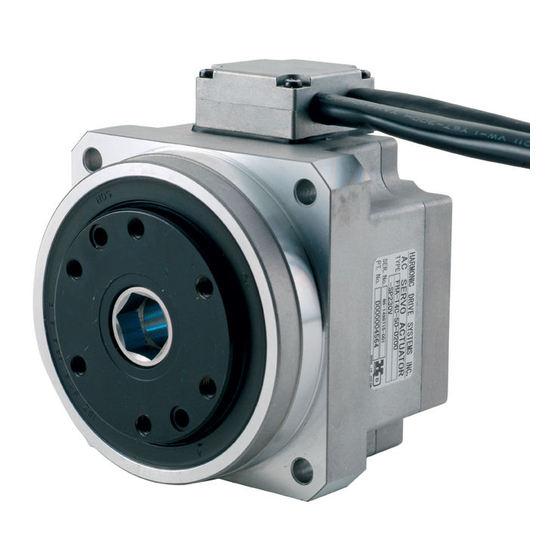
- Page 1 AC Servo Actuator F H A - C m i n i s e r i e s m a n u a l ISO14001 ISO9001...
- Page 2 Introduction Introduction Thank you very much for your purchasing our FHA-Cmini series servo actuator. Wrong handling or use of this product may result in unexpected accidents or shorter life of the product. Read this document carefully and use the product correctly so that the product can be used safely for many years.
-
Page 3: Safety Guide
SAFETY GUIDE SAFETY GUIDE To use this actuator safely and correctly, be sure to read SAFETY GUIDE and other parts of this document carefully and fully understand the information provided herein before using the driver. NOTATION Important safety information you must note is provided herein. Be sure to observe these instructions. Indicates a potentially hazardous situation, which, if not avoided, could result in death or serious personal injury. -
Page 4: Safety Note
SAFETY GUIDE SAFETY NOTE CAUTIONS FOR ACTUATORS AT APPLICATION DESIGNING Always use under followings conditions: The actuator is designed to be used indoors. Observe the following conditions: ・ Ambient temperature: 0℃ to 40℃ CAUTION ・ Ambient humidity: 20% to 80%RH (Non-condensation) ・... - Page 5 SAFETY GUIDE CAUTIONS FOR DRIVERS AT APPLICATION DESIGNING Always use drivers under followings conditions: ・ Mount in a vertical position keeping sufficient distance to other devices to let heat generated by the driver radiate freely. CAUTION ・ 0℃ to 50℃, 95% RH or below (Non condensation) ・...
- Page 6 SAFETY GUIDE Do not make a voltage resistance test. ・ Failure to observe this caution may result in damage of the control unit. ・ Please consult our sales office, if you intent to make a voltage CAUTION resistance test. Do not operate control units by means of power ON/OFF switching.
-
Page 7: Structure Of This Document
Structure of this document Structure of this document Outlines of product models, specifications, external drawings, etc., Chapter 1 Outlines are explained. Selection guidelines for the FHA-C mini series actuator are explained Chapter 2 Selection guidelines in this chapter. This chapter explains the procedure for installing the FHA-C mini Chapter 3 Installation series actuator. -
Page 8: Table Of Contents
Contents SAFETY GUIDE ..................... 1 NOTATION ......................1 LIMITATION OF APPLICATIONS................1 SAFETY NOTE ...................... 2 Structure of this document ..................5 Contents ......................... 6 Chapter 1 Outlines Outlines ...................... 1-1 Main features....................... 1-1 Model ......................1-2 Combinations with drivers ................1-3 Specifications ..................... -
Page 9: Contents
Contents Chapter 2 Selection guidelines Connecting power cables ................2-1 Change in moment of inertia of load ............2-2 Verifying and examining load weights ............2-3 Examining operating status ................ 2-7 Examining actuator rotation speed ..............2-7 Calculating and examining load inertia moment ........... 2-7 Load torque calculation .................. - Page 11 Chapter Outlines Outlines of product models, specifications, external drawings, etc., are explained in this chapter. Outlines ··········································································· 1-1 Model ············································································· 1-2 Combinations with drivers···················································· 1-3 Specifications ··································································· 1-4 External drawing ······························································· 1-6 Mechanical accuracy ·························································· 1-9 Uni-directional positional accuracy ······································ 1-10 Detector resolution ····························································...
-
Page 12: Main Features
1-1 Outlines Outlines FHA-C mini series AC Servo Actuators provide high torque and highly accurate rotary operation. These integrated AC Servo Actuators are each composed of a thin type speed reducer ® HarmonicDrive for precision control from models No. 8 to No. 14 and a flat AC servo motor. The first feature of the FHA-C mini series actuators is their shape. -
Page 13: Model
1-2 Model Model Model names for the FHA-C mini series actuators and how to read the symbols are explained below. Incremental encoder FHA-8 C-30-E200-C □ □ Model: AC Servo Actuator FHA-C mini series Model No.: 8, 11, 14 Version symbol ®... -
Page 14: Combinations With Drivers
1-3 Combinations with drivers Combinations with drivers The HA-800, HA-680 or RF2H21A0AHD driver is available for use with FHA-C mini series actuators. The driver comes in models based on input voltages. The correct combinations are listed below. Combined driver Input Actuator Model Encoder... -
Page 15: Specifications
1-4 Specifications Specifications Input voltage 100VAC/200VAC specification The specifications for the FHA-C mini series actuators with 100VAC/200VAC input voltages are as follows. FHA-8C FHA-11C FHA-14C Model Item N·m Maximum torque Note 3 kgf·m 0.18 0.34 0.49 0.46 0.85 0.92 Max. rotational speed r/min N·m/A Torque constant... -
Page 16: Input Voltage: 24Vdc Specification
1-4 Specifications Note 2: The table shows the output shaft values of the actuators. Note 3: The value when combined with a HA-800 driver. Note 4: All values are typical. Note 5: The values listed below are for the detector resolution. Incremental encoder: (motor shaft encoder quadruplicate resolution) x (reduction ratio). -
Page 17: External Drawing
1-5 External drawing External drawing The external drawings of FHA-C mini series actuators are shown below. Side-leading cables (standard specification/incremental encoder model) FHA-8C-xx-E200-C Unit: mm (third angle projection) FHA-11C-xx-E200-C FHA-14C-xx-E200-C Cable pullout (common specification) Motor cable Motor connector Encoder connector Encoder cable Note: Tolerances may vary due to product manufacturing method (foundry piece, machine-finished good). -
Page 18: Side-Leading Rear Cables (Option Specification/Incremental Encoder Model)
1-5 External drawing Side-leading rear cables (option specification/incremental encoder model) FHA-8C-xx-E200-CK Unit: mm (third gle projection) FHA-11C-xx-E200-CK FHA-14C-xx-E200-CK Cable pullout (common specification) Motor cable Motor connector Encoder connector Encoder cable Note: Tolerances may vary due to product manufacturing method (foundry piece, machine-finished good). -
Page 19: Side-Leading Cables (Standard Specification/Absolute Encoder Model)
1-5 External drawing Side-leading cables (standard specification/absolute encoder model) FHA-8C-xx-12S17bA-C Unit: mm (third angle projection) Output rotary unit FHA-11C-xx-12S17bA-C Output rotary unit FHA-14C-xx-12S17bA-C Output rotary unit Cable pullout (common specification) Note: Tolerances may vary due to product manufacturing method (foundry piece, machine-finished good). -
Page 20: Mechanical Accuracy
1-6 Mechanical accuracy Mechanical accuracy The mechanical accuracies of the output shaft and mounting flange are shown below for FHA-C mini series actuators. Mechanical accuracy Unit: mm Accuracy items FHA-8C FHA-11C FHA-14C 1. Output shaft 0.010 surface runout 2. Deflection of 0.010 output shaft 3. -
Page 21: Uni-Directional Positional Accuracy
1-7 Uni-directional positional accuracy Uni-directional positional accuracy The uni-directional positional accuracy means the maximum positional difference between the actual rotated angle from the datum position and its theoretical rotational angle in 1 revolution when series of positionings are performed in the same rotation direction. (refer to JIS B-6201-1987.) ®... -
Page 22: Detector Resolution
1-8 Detector resolution Detector resolution The motors of the FHA-C mini series actuators are equipped with an incremental encoder of 2,000 pulses per revolution, and an absolute encoder of 131,072 pulses per revolution. The function reduces ® the motor output to 1/30, 1/50 and 1/100 by using a speed reducer HarmonicDrive for precision control. -
Page 23: Rigidity
1-9 Rigidity Rigidity Moment stiffness The moment stiffness refers to the torsional stiffness when a moment load is applied to the output shaft of the actuator (shown below). For example, when a load is applied to the end of an arm attached on the actuator output shaft, the face of the output shaft tilts in proportion to the moment load (shown below). -
Page 24: Rotation Direction Torsional Stiffness
1-9 Rigidity Rotation direction torsional stiffness If a torque is applied to the output shaft of the actuator with the servo locked, the output shaft generates a torsional stress roughly in proportion to the torque. The upper right figure shows the torsional angle of the output shaft when a torque starting from zero and increased to positive side [+T ] and negative side [–T... -
Page 25: Rotation Direction
1-10 Rotation direction 1-10 Rotation direction Forward rotation direction of the actuator is defined as clockwise (CW) rotation as viewed from the output shaft side when a forward command is given to a FHA-C mini series actuator from a driver. This rotation direction can be changed on the driver by selecting [Parameter settings]. -
Page 26: Shock Resistance
1-11 Shock resistance 1-11 Shock resistance The shock acceleration when applying a impact in the up/down and left/right directions with the center shaft of the actuator installed horizontally is as follows. Shock acceleration: 294 m/s Direction: top/bottom, right/left, front/back Rear Repeating times: three each Left Right... -
Page 27: Resistance To Vibration
1-12 Resistance to vibration 1-12 Resistance to vibration The resistance to vibration of the actuator is as follows, and this value is the same in up/down, left/right and front/rear directions: Vibration acceleration: 24.5 m/s (frequency: 10 to 400Hz) This specification does not have a warranty period and terms against fletting wear of mechanical parts due to micro-vibration. -
Page 28: Operable Range
1-13 Operable range 1-13 Operable range The graphs below show the operable range when a FHA-C mini series actuator and an HA-800 or HA-680 driver combination is selected. Refer to [Chapter 2 Selection guidelines] for the most efficient use of FHA-C mini series actuators' output. (1) Continuous motion range The range allows continuous operation for the actuator. - Page 29 1-13 Operable range 200V FHA-8C-30 FHA-8C-50 Input voltage: 200V Input voltage: 200V Torque [Nm] Radiation plate: 150 x 150 x 6(mm) Torque [Nm] Radiation plate: 150 x 150 x 6(mm) Motion range during acceleration and deceleration Motion range during acceleration and deceleration 50% duty range 50% duty range...
- Page 30 1-13 Operable range Torque [Nm] Input voltage: 24V Radiation plate: 150 x 150 x 6(mm) Motion range during acceleration and deceleration 50% duty range Continuous motion range Rotation speed [r/min] FHA-11C 100V FHA-11C-30 FHA-11C-50 Input voltage: 100V Input voltage: 100V Torque [Nm] Torque [Nm]...
- Page 31 1-13 Operable range 200V FHA-11C-30 FHA-11C-50 Input voltage: 200V Input voltage: 200V Torque [Nm] Torque [Nm] Radiation plate: 150 x 150 x 6(mm) Radiation plate: 150 x 150 x 6(mm) Motion range during acceleration and Motion range during deceleration acceleration and deceleration...
- Page 32 1-13 Operable range Input voltage: 24V Torque [Nm] Radiation plate: 150 x 150 x 6(mm) Motion range during acceleration and deceleration 50% duty range Continuous motion range Rotation speed [r/min] FHA-14C 100V FHA-14C-30 FHA-14C-50 Input voltage: 100V Input voltage: 100V Torque [Nm] Torque [Nm]...
- Page 33 1-13 Operable range 200V FHA-14C-50 FHA-14C-30 Input voltage: 200V Input voltage: 200V Torque [Nm] Torque [Nm] Radiation plate: 200 x 200 x 6(mm) Radiation plate: 200 x 200 x 6(mm) Motion range during Motion range during acceleration and acceleration and deceleration deceleration...
- Page 34 1-13 Operable range 24V Input voltage: 24V Input voltage: 24V Torque [Nm] Radiation plate: 200 x 200 x 6(mm) Torque [Nm] Radiation plate: 200 x 200 x 6(mm) Motion range during Motion range during acceleration and acceleration and deceleration deceleration 50% duty range 50% duty range...
-
Page 35: Cable Specifications
1-14 Cable specifications 1-14 Cable specifications The following tables show specifications of the motor and encoder cables of the FHA-C mini series actuators. Motor power cable Pin layout Pin No. Color Motor cable Motor phase-U White Motor phase-V Black Motor phase-W Green/Yellow ―... - Page 36 1-14 Cable specifications Absolute encoder Pin layout Pin No. Signal name Remarks Color White Power supply input +5V Black GND(Vcc) Power supply input 0V (GND) Blue Serial signal differential output (+) Purple Serial signal differential output (-) ― No connection ―...
- Page 37 Chapter Selection guidelines The following explains the guidelines for selecting actuators. Connecting power cables ···················································· 2-1 Change in moment of inertia of load ······································ 2-2 Verifying and examining load weights ····································· 2-3 Examining operating status ·················································· 2-7...
-
Page 38: Connecting Power Cables
2-1 Connecting power cables Selection guidelines Connecting power cables To achieve high accuracy and performance, select a FHA-C mini series actuator where the allowable load inertia moment (reference value) specified for the applicable model No. is not exceeded. Refer to appendix 2 (Apx-3) for the calculation of inertia moment. Inertia moment (kg·m (kgf·cm·s... -
Page 39: Change In Moment Of Inertia Of Load
2-2 Change in moment of inertia of load Selection guidelines Change in moment of inertia of load ® FHA-C mini series actuators include HarmonicDrive gearing that has a high reduction ratio. Because of this, the effects of change in load inertia moment on the servo performance are minimal. In comparison to direct servo drive mechanisms, therefore, this benefit allows the load to be driven with a better servo response. -
Page 40: Verifying And Examining Load Weights
2-3 Verifying and examining load weights Selection guidelines Verifying and examining load weights The FHA-C mini series actuator incorporates a precise cross roller bearing for directly supporting an external load (output flange). To demonstrate the full ability of the actuator, verify the maximum load weight as well as the life and static safety coefficient of the cross roller bearing. - Page 41 2-3 Verifying and examining load weights Selection guidelines Calculating average loads (average radial and axial loads, average output rotational speed) When the radial and/or axial loads vary during motion, calculate and verify the life of the cross roller bearing converting the loads to their average values. ...
- Page 42 2-3 Verifying and examining load weights Selection guidelines Dynamic equivalent radial load Formula (6): Dynamic equivalent radial load 2(Fr ⋅ ⋅ ⋅ Symbols used in the formulas Dynamic equivalent N(kgf) radial load Frav Average radial load N(kgf)
- Page 43 2-3 Verifying and examining load weights Selection guidelines Static equivalent radial load Formula (9): Static equivalent radial load 0.44Fa Symbols used in the formulas Frmax Max. radial load N(kgf) See Fig.1. Famax Max. axial load N(kgf) See Fig.1. Refer to the maximum load N·m Mmax...
-
Page 44: Examining Operating Status
2-4 Examining operating status Selection guidelines Examining operating status The actuator generates heat, and starting and braking currents to the motor flow at a high frequency if during its active state it is started/stopped repeatedly (duty cycle). Therefore, it is necessary to examine the duty cycle. -
Page 45: Load Torque Calculation
2-4 Examining operating status Selection guidelines Load torque calculation Calculate the load torque as follows: Rotary motion The rotary torque for the rotating mass W on Mass: W the ring of radius r from the center of rotation is shown in the figure to the right. Radius: r ×... -
Page 46: Acceleration Time And Deceleration Time
2-4 Examining operating status Selection guidelines Linear operation (horizontal operation) The rotary torque when the mass W moves horizontally due to the screw of pitch P is shown below. Mass: W × µ × × Pitch: P × π T: Rotary torque (N·m) Friction: μ... -
Page 47: Duty Cycles
2-4 Examining operating status Selection guidelines Based on the above formula, the actuator's friction torque TF is calculated as 6.6 x 1.6 - 8.3 = 2.3 N·m. Therefore, the acceleration time and deceleration time can be obtained as follows from the above formulas: = (0.017 + 0.04) x 2 x π... -
Page 48: Duty Factor Graphs
2-4 Examining operating status Selection guidelines If the %ED is over 100%, the operation pattern FHA-11C-50 load (possible reduction) Radiation plate: 150 x 150 x 6(mm) actuator model No. etc., must be reexamined. Operable range 100 V 200 V 24 V KL = 0.33... - Page 49 2-4 Examining operating status Selection guidelines FHA-8C-100 FHA-11C-100 Radiation plate: 150 x 150 x 6(mm) Radiation plate: 150 x 150 x 6(mm) Operable range 100 V Operable range 200 V 100 V 24 V 200 V 24 V 0.67 0.67 KL = 0.33...
-
Page 50: Examining Effective Torque And Average Rotation Speed
2-4 Examining operating status Selection guidelines Examining effective torque and average rotation speed Consider the following two points when obtaining the effective torque and average rotational speed. The effective torque should be less than the allowable continuous torque. The average rotational speed should be less than the allowable continuous rotational speed. Using the following formula, calculate the effective torque T and average rotation speed N when... -
Page 51: Overload Detection Time
2-4 Examining operating status Selection guidelines Overload detection time If the FHA-C mini series is intermittently driven more than its allowable continuous torque, the output time and continuous torque is limited by a overload detection function in the driver even if the duty cycle is allowed. - Page 52 2-4 Examining operating status Selection guidelines 2-15...
-
Page 53: Chapter 3 Installation
Chapter Installation This chapter explains the procedure for installing the FHA-C mini series actuator. Receiving inspection ·························································· 3-1 Notices on handling ··························································· 3-3 Installation location and installation ········································ 3-4... -
Page 54: Receiving Inspection
3-1 Receiving inspection Installation Receiving inspection Check the following items after unpacking the package. Check procedure Check the items thoroughly for damage sustained during transportation. If any item is damaged, immediately contact the dealer. The nameplate is found on the side face of the FHA-C mini series actuator. Check the TYPE field on the nameplate to confirm that it is indeed the model you have ordered. - Page 55 3-1 Receiving inspection Installation The driver's model code is shown in the TYPE field of the driver's nameplate. The last digits of this model code indicate the input voltage to be input. 200: 3-phase/single-phase 200V power supply 100: indicates a 100VAC power. 24: indicates a 24VDC power.
-
Page 56: Notices On Handling
3-2 Notices on handling Installation Notices on handling Handle the FHA-C mini series actuator carefully by observing the notices specified below. Do not connect the actuator terminals directly to the power supply. The actuator may burn and cause fire or electric shock. WARNING (1) Do not apply any excessive force or impact, especially to the actuator's output shaft. -
Page 57: Installation Location And Installation
3-3 Installation location and installation Installation Installation location and installation Environment of installation location The environmental conditions of the installation location for FHA-C mini series actuators must be as follows. Determine an appropriate installation location by observing these conditions without fail. ... - Page 58 3-3 Installation location and installation Installation Fasten the flange of the actuator on the load machine with flat washers and high-tension bolts. When tightening, use a torque wrench to control the tightening torque. The tightening torques are shown in the table below: FHA-8C FHA-11C FHA-14C...
-
Page 59: Appendix
Appendix This chapter explains the default settings, etc. Apx-1 Unit conversion ··························································Apx-1 Apx-2 Calculating inertia moment ············································Apx-3... - Page 60 Unit conversion Appendix 13-1 Unit conversion Apx- This manual employs SI system for units. Conversion factors between the SI system and other systems are as follows: (1) Length SI system Unit Factor 0.3048 0.0254 Unit Factor 3.281 39.37 SI system (2) Linear speed SI system Unit...
- Page 61 Unit conversion (8) Angular acceleration SI system rad/s Unit deg/s deg/min Factor 0.01755 2.93 x 10 Unit deg/s deg/min Factor 57.3 3.44 x 10 SI system rad/s (9) Torque SI system N·m Unit kgf·m lb·ft lb·in oz·in Factor 9.81 1.356 0.1130 7.06 x 10 Unit kgf·m...
-
Page 62: Formula Of Mass And Inertia Moment
Calculating inertia moment Appendix 13-2 Calculating inertia moment Apx- Formula of mass and inertia moment (1) Both centerlines of rotation and gravity are the same: The following table includes formulas to calculate mass and inertia moment. m: mass (kg); Ix, Iy, Iz: inertia moments which rotate around x-, y-, z-axes respectively (kg·m G: distance from end face of gravity center ρ: specific gravity Unit Length: m;... - Page 63 Calculating inertia moment Mass, inertia, Mass, inertia, Object form Object form gravity center gravity center Rhombus pillar Hexagonal pillar ρ ρ B√3 Ix = Isosceles triangle Right triangle pillar ABCρ...
-
Page 64: Inertia Moment Of A Cylinder
Calculating inertia moment Appendix Inertia moment of a cylinder The moment of inertia of a cylinder Inertia moment (kg·m Length (mm) may be obtained from the graphs to 1000 the right. Inertia moment (specific gravity: 2.7) 1000 FHA-40C-160 FHA-40C-100 FHA-32C-160 Radius FHA-25C-160 FHA-32C-100... - Page 65 Index Accuracy ............. 1-9 Maximum load ........... 2-3 Model ..............1-2 Bearing ............... 2-5 Operating rotation speed ........2-7 Outlines .............. 1-1 Cables ............... 1-24 Combined ............1-3 Power supply ............2-1 Duty ..............2-10 Radial load ............2-6 Resolution ............1-11 Rigidity .............
- Page 67 This limited warranty does not apply to any product that has been subject to: (1) Improper handling or use by the customer; (2) Modification or repair carried out other than by Harmonic Drive Systems, Inc.; (3) Failure not attributable to this product; or (4) Natural disaster or any other event beyond the control of Harmonic Drive Systems, Inc.
- Page 68 FAX: +81(0)263-83-6901 Harmonic Drive AG/Hoenbergstrasse 14, 65555 Limburg, Germany TEL+049-6431-5008-0 FAX+049-6431-5008-18 Harmonic Drive SE: Hoenbergstrasse 14, 65555 Limburg, Germany Harmonic Drive L.L.C/247 Lynnfield Street, Peabody, MA, 01960, U.S.A. TEL: +049-6431-5008-0 FAX: +049-6431-5008-18 TEL+1- 978-532-1800 FAX+1- 978-532-9406 Harmonic Drive 247 Lynnfield Street, Peabody, MA, 01960, U.S.A.
Need help?
Do you have a question about the FHA-Cmini Series and is the answer not in the manual?
Questions and answers