Table of Contents
Advertisement
Quick Links
Advertisement
Table of Contents

Subscribe to Our Youtube Channel
Related Manuals for Harmonic Drive CHA


Summary of Contents for Harmonic Drive CHA
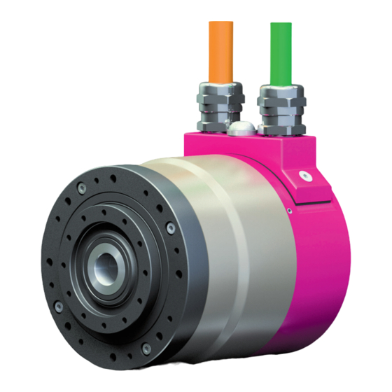
- Page 1 Engineering Data AC Servo Actuators CHA QUICKLINK www.harmonicdrive.de/1010...
-
Page 2: Table Of Contents
Contents General ..............................03 Description of Safety Alert Symbols ...........................04 Disclaimer and Copyright ..............................04 Safety and Installation Instructions ....................05 Hazards ....................................05 Intended Purpose .................................06 Non Intended Purpose ................................07 Declaration of Conformity ..............................07 Technical Description ........................... 08 Product Description ................................08 Ordering Code .................................. -
Page 3: General
For the configuration of drive systems using the products of Harmonic Drive AG, you may require additional documents. Documentation is provided for all products offered by Harmonic Drive AG and can be found in pdf format on the website. www.harmonicdrive.de Third-party systems Documentation for parts supplied by third party suppliers, associated with Harmonic Drive®... -
Page 4: Description Of Safety Alert Symbols
1.1 Description of Safety Alert Symbols Symbol Meaning Indicates an imminent hazardous situation. If this is not avoided, death or DANGER serious injury could occur. Indicates a possible hazard. Care should be taken or death or serious injury may WARNING result. -
Page 5: Safety And Installation Instructions
2. Safety and Installation Instructions Please take note of the information and instructions in this document. Specialy designed models may differ in technical de- tail. If in doubt, we strong recommend that you contact the manufacturer, giving the type designation and serial number for clarification. -
Page 6: Intended Purpose
2.2 Intended Purpose The Harmonic Drive® servo actuators and motors are intended for industrial or commercial applications. They comply with the relevant parts of the harmonised EN 60034 standards series. -
Page 7: Non Intended Purpose
• Special devices for use in annual markets or leisure parks 2.4 Declaration of Conformity The Harmonic Drive® servo actuators and motors described in the engineering data comply with the Low Voltage Directive. A copy of the EC conformity declaration is supplied in the appendix. -
Page 8: Technical Description
By combining the CHA Actuators with the specially adapted YukonDrive® Servo Controllers, it is possible to provide a single source supply for a pre-configured drive system tailored to suit your application. Alternatively, the flexible configuration of the actuator ensures compatibility with almost any servo controller on the market. -
Page 9: Ordering Code
3.2 Ordering Code Table 9.1 Size Motor winding and Motor feed- Special Series Ratio Brake Option 1 Option 2 Version connector configuration back system design C1024 M512P Cable/ According Sensor connec- to customer D2048 requirements M128S Ordering code C1024 Variations in bold print are available at short notice, subject to prior sale. Table 9.2 Table 9.3 Motor winding and connector configuration... - Page 10 Combinations Table 10.1 Size Version Ratio ...
-
Page 11: Technical Data
3.3.1 General Technical Data CHA-xxA-E Table 11.1 Insulation class (EN 60034-1) Insulation resistance (500VDC) MΩ Insulation voltage (10s) Lubrication Harmonic Drive Flexolub A1 Degree of predection (EN 60034-5) IP65 Ambient operating temperature ° C 0 … 40 Ambient storage temperature ° C -20 …... -
Page 12: Actuator Data
3.3.2 Actuator Data Table 12.1 Symbol [Unit] CHA-14A-E Motor feedback system RES / D2048 / M128S Ratio i [ ] Maximum output torque [Nm] Maximum output speed [rpm] Maximum current Continuous stall torque [Nm] Continuous stall current Maximum DC bus voltage DCmax Electrical time constant (20°... - Page 13 Table 13.1 Symbol [Unit] CHA-14A-H/N Motor feedback system RES / D2048 / M128S Ratio i [ ] Maximum output torque [Nm] Maximum output speed [rpm] Maximum current Continuous stall torque [Nm] Continuous stall current Maximum DC bus voltage DCmax Electrical time constant (20° C) [ms] Mechanical time constant (20°...
- Page 14 Moment of Inertia Table 14.1 Symbol [Unit] CHA-14A Motor feedback system Ratio i [ ] Moment of Inertia output side Moment of inertia without brake [kgm²] 0.031 0.087 0.222 0.347 Moment of inertia with brake [kgm²] 0.039 0.109 0.280 0.438...
- Page 15 Performance Characteristics The performance curves shown below are valid for the specified ambient operating temperature if the motor terminal voltage is higher or equal to the values given in the ratings table. CHA-14A-30-E Berechnung von Antriebskennlinien CHA-14A-50-E CHA-14A-30-E CHA-14A-50-E Illustration 15.1 Illustration 15.2...
- Page 16 CHA-14A-30-H/L Berechnung von Antriebskennlinien CHA-14A-50-H/L CHA-14A-30-H/N CHA-14A-50-H/N Illustration 16.1 Illustration 16.2 Drehzahl Drehmoment CHA-14A-30-H/L CHA-14A-50-H/L Maximal S3-ED 25% Speed [rpm] Speed [rpm] S3-ED 50% CHA-14A-80-H/L Berechnung von Antriebskennlinien CHA-14A-100-H/L CHA-14A-80-H/N CHA-14A-100-H/N Illustration 16.3 Illustration 16.4 Drehzahl Drehmoment CHA-14A-80-H/L CHA-14A-100-H/L Maximal...
- Page 17 Table 17.1 Symbol [Unit] CHA-17A-E Motor feedback system RES / D2048 / M128S Ratio i [ ] Maximum output torque [Nm] Maximum output speed [rpm] Maximum current 10.3 Continuous stall torque [Nm] Continuous stall current Maximum DC bus voltage DCmax Electrical time constant (20°...
- Page 18 Table 18.1 Symbol [Unit] CHA-17A-H/N Motor feedback system RES / D2048 / M128S Ratio i [ ] Maximum output torque [Nm] Maximum output speed [rpm] Maximum current Continuous stall torque [Nm] Continuous stall current Maximum DC bus voltage DCmax Electrical time constant (20° C) [ms] Mechanical time constant (20°...
- Page 19 Moment of Inertia Table 19.1 Symbol [Unit] CHA-17A Motor feedback system Ratio i [ ] Moment of Inertia output side Moment of inertia without brake [kgm²] 0.095 0.264 0.676 1.056 1.520 Moment of inertia with brake [kgm²] 0.104 0.289 0.741 1.158...
- Page 20 Performance Characteristics The performance curves shown below are valid for the specified ambient operating temperature if the motor terminal voltage is higher or equal to the values given in the ratings table. CHA-17A-30-E Berechnung von Antriebskennlinien CHA-17A-50-E CHA-17A-30-E CHA-17A-50-E Illustration 20.1 Illustration 20.2...
- Page 21 CHA-17A-30-H/L Berechnung von Antriebskennlinien CHA-17A-50-H/L CHA-17A-30-H/N CHA-17A-50-H/N Illustration 21.1 Illustration 21.2 Drehzahl Drehmoment CHA-17A-30-H/L CHA-17A-50-H/L Maximal S3-ED 25% !"##$%&'"()% Drehzahl [min Speed [rpm] Speed [rpm] S3-ED 50% CHA-17A-80-H/L Berechnung von Antriebskennlinien CHA-17A-100-H/L CHA-17A-80-H/N CHA-17A-100-H/N Illustration 21.3 Illustration 21.4 Drehzahl Drehmoment...
- Page 22 Table 22.1 Symbol [Unit] CHA-20A Motor feedback system C1024 Ratio i [ ] Maximum output torque [Nm] Maximum output speed [rpm] Maximum current Continuous stall torque [Nm] Continuous stall current Maximum DC bus voltage DCmax Electrical time constant (20° C) [ms] Mechanical time constant (20°...
- Page 23 Performance Characteristics The performance curves shown below are valid for the specified ambient operating temperature if the motor terminal voltage is higher or equal to the values given in the ratings table. Berechnung von Antriebskennlinien CHA-20A-50 CHA-20A-30 CHA-20A-30 CHA-20A-50 Illustration 23.1 Illustration 23.2...
- Page 24 Table 24.1 Symbol [Unit] CHA-25A Motor feedback system C1024 Ratio i [ ] Maximum output torque [Nm] Maximum output speed [rpm] Maximum current Continuous stall torque [Nm] Continuous stall current Maximum DC bus voltage DCmax Electrical time constant (20° C) [ms] Mechanical time constant (20°...
- Page 25 Performance Characteristics The performance curves shown below are valid for the specified ambient operating temperature if the motor terminal voltage is higher or equal to the values given in the ratings table. CHA-25A-30 n i l CHA-25A-30 CHA-25A-50 Illustration 25.1 Illustration 25.2...
- Page 26 Table 26.1 Symbol [Unit] CHA-32A Motor feedback system C1024 Ratio i [ ] Maximum output torque [Nm] Maximum output speed [rpm] Maximum current Continuous stall torque [Nm] Continuous stall current Maximum DC bus voltage DCmax Electrical time constant (20° C) [ms] Mechanical time constant (20°...
- Page 27 Performance Characteristics The performance curves shown below are valid for the specified ambient operating temperature if the motor terminal voltage is higher or equal to the values given in the ratings table. n i l CHA-32A-30 CHA-32A-50 Illustration 27.1 Illustration 27.2...
- Page 28 Table 28.1 Symbol [Unit] CHA-40A Motor feedback system C1024 Ratio i [ ] Maximum output torque [Nm] Maximum output speed [rpm] Maximum current 11.8 Continuous stall torque [Nm] Continuous stall current Maximum DC bus voltage DCmax Electrical time constant (20° C) [ms] Mechanical time constant (20°...
- Page 29 Performance Characteristics The performance curves shown below are valid for the specified ambient operating temperature if the motor terminal voltage is higher or equal to the values given in the ratings table. n i l CHA-40A-50 CHA-40A-80 Illustration 29.1 Illustration 29.2...
- Page 30 Table 30.1 Symbol [Unit] CHA-50A Motor feedback system C1024 Ratio i [ ] Maximum output torque [Nm] 1080 1180 Maximum output speed [rpm] Maximum current 10.2 Continuous stall torque [Nm] Continuous stall current Maximum DC bus voltage DCmax Electrical time constant (20° C) [ms] Mechanical time constant (20°...
- Page 31 Performance Characteristics The performance curves shown below are valid for the specified ambient operating temperature if the motor terminal voltage is higher or equal to the values given in the ratings table. n i l CHA-50A-50 CHA-50A-80 Illustration 31.1 Illustration 31.2...
- Page 32 Table 32.1 Symbol [Unit] CHA-58A Motor feedback system C1024 Ratio i [ ] Maximum output torque [Nm] 1020 1480 1590 1720 1840 Maximum output speed [rpm] Maximum current 14.4 12.8 11.1 10.0 Continuous stall torque [Nm] 1080 Continuous stall current...
- Page 33 Performance Characteristics The performance curves shown below are valid for the specified ambient operating temperature if the motor terminal voltage is higher or equal to the values given in the ratings table. n i l CHA-58A-50 CHA-58A-80 Illustration 33.1 Illustration 33.2...
- Page 34 Table 34.1 Symbol [Unit] CHA-20A Motor feedback system M512P Ratio i [ ] Maximum output torque [Nm] Maximum output speed [rpm] Maximum current Continuous stall torque [Nm] Continuous stall current Maximum DC bus voltage DCmax Electrical time constant (20° C) [ms] Mechanical time constant (20°...
- Page 35 Performance Characteristics The performance curves shown below are valid for the specified ambient operating temperature if the motor terminal voltage is higher or equal to the values given in the ratings table. CHA-20A-30 Berechnung von Antriebskennlinien CHA-20A-50 CHA-20A-30 CHA-20A-50 Illustration 35.1 Illustration 35.2...
- Page 36 Table 36.1 Symbol [Unit] CHA-25A Motor feedback system M512P Ratio i [ ] Maximum output torque [Nm] Maximum output speed [rpm] Maximum current Continuous stall torque [Nm] Continuous stall current Maximum DC bus voltage DCmax Electrical time constant (20° C) [ms] Mechanical time constant (20°...
- Page 37 Performance Characteristics The performance curves shown below are valid for the specified ambient operating temperature if the motor terminal voltage is higher or equal to the values given in the ratings table. CHA-25A-30 n i l CHA-25A-30 CHA-25A-50 Illustration 37.1 Illustration 37.2...
- Page 38 Table 38.1 Symbol [Unit] CHA-32A Motor feedback system M512P Ratio i [ ] Maximum output torque [Nm] Maximum output speed [rpm] Maximum current Continuous stall torque [Nm] Continuous stall current Maximum DC bus voltage DCmax Electrical time constant (20° C) [ms] Mechanical time constant (20°...
- Page 39 Performance Characteristics The performance curves shown below are valid for the specified ambient operating temperature if the motor terminal voltage is higher or equal to the values given in the ratings table. n i l CHA-32A-30 CHA-32A-50 Illustration 39.1 Illustration 39.2...
- Page 40 Table 40.1 Symbol [Unit] CHA-40A Motor feedback system M512P Ratio i [ ] Maximum output torque [Nm] Maximum output speed [rpm] Maximum current 11.8 Continuous stall torque [Nm] Continuous stall current Maximum DC bus voltage DCmax Electrical time constant (20° C) [ms] Mechanical time constant (20°...
- Page 41 Performance Characteristics The performance curves shown below are valid for the specified ambient operating temperature if the motor terminal voltage is higher or equal to the values given in the ratings table. n i l CHA-40A-50 CHA-40A-80 Illustration 41.1 Illustration 41.2...
- Page 42 Table 42.1 Symbol [Unit] CHA-50A Motor feedback system M512P Ratio i [ ] Maximum output torque [Nm] 1080 1180 Maximum output speed [rpm] Maximum current 10.2 Continuous stall torque [Nm] Continuous stall current Maximum DC bus voltage DCmax Electrical time constant (20° C) [ms] Mechanical time constant (20°...
- Page 43 Performance Characteristics The performance curves shown below are valid for the specified ambient operating temperature if the motor terminal voltage is higher or equal to the values given in the ratings table. n i l CHA-50A-50 CHA-50A-80 Illustration 43.1 Illustration 43.2...
- Page 44 Table 44.1 Symbol [Unit] CHA-58A Motor feedback system M512P Ratio i [ ] Maximum output torque [Nm] 1020 1480 1590 1720 1840 Maximum output speed [rpm] Maximum current 14.4 12.8 11.1 10.0 Continuous stall torque [Nm] 1080 Continuous stall current...
- Page 45 Performance Characteristics The performance curves shown below are valid for the specified ambient operating temperature if the motor terminal voltage is higher or equal to the values given in the ratings table. n i l CHA-58A-50 CHA-58A-80 Illustration 45.1 Illustration 45.2...
-
Page 46: Dimensions
3.3.3 Dimensions Detailed 2D drawings and 3D models can be found at the following Quicklink: www.harmonicdrive.de/CAD1010 QUICKLINK CHA-14A-E CHA-17A-E Illustration 46.1 [mm] Illustration 46.2 [mm] Table 46.3 Symbol [Unit] CHA-14A-E CHA-17A-E Motor feedback system RES / D2048/ M128S RES / D2048/ M128S... - Page 47 CHA-20A CHA-25A Illustration 47.1 [mm] Illustration 47.2 [mm] Table 47.3 Symbol [Unit] CHA-20A CHA-25A Motor feedback system C1024 C1024 Length (without brake) L [mm] 132.5 Length (with brake) L1 [mm] Standard cable length l [m] approx. 1.8 approx. 1.8 CHA-32A CHA-40A Illustration 47.4...
- Page 48 CHA-50A CHA-58A Illustration 48.1 [mm] Illustration 48.2 [mm] Table 48.3 Symbol [Unit] CHA-50A CHA-58A Motor feedback system C1024 C1024 Length (without brake) L [mm] Length (with brake) L1 [mm] Standard cable length l [m] approx. 1.8 approx. 1.8 CHA-20A-M512P CHA-25A-M512P Illustration 48.4...
- Page 49 CHA-32A-M512P CHA-40A-M512P Illustration 49.1 [mm] Illustration 49.2 [mm] Table 49.3 Symbol [Unit] CHA-32A CHA-40A Motor feedback system M512P M512P Length (without brake) L [mm] 144.5 Length (with brake) L1 [mm] CHA-50A-M512P CHA-58A-M512P Illustration 49.4 [mm] Illustration 49.5 [mm] Table 49.6...
-
Page 50: Accuracy
3.3.4 Accuracy Table 50.1 Symbol CHA-14A CHA-17A CHA-20A CHA-25A [Unit] Ratio i [ ] > 50 > 50 > 50 > 50 Transmission accuracy [arcmin] < 2 < 1.2 < 1 < 2 < 1.2 < 1 < 1.5 < 1 <... -
Page 51: Output Bearing
3.3.6 Output Bearing CHA series AC hollow shaft Servo Actuators incorporate a high stiffness cross roller bearing to support output loads. This specially developed bearing can withstand high axial and radial forces as well as high tilting moments. The reduction gear is thus protected from external loads, so guaranteeing a long life and consistent performance. -
Page 52: Motor Feedback Systems
Resolution In conjunction with the Harmonic Drive AG high precision gears, the output side position can be recorded via the motor feed- back system without any additional angle encoders having to be used. The resolution of the motor feedback system can also be multiplied by gear ratio. - Page 53 Signal form sinusoidal Number of pulses [C / D] Reference signal Accuracy [arcsec] ±12 Incremental resolution (motor side) inc [ ] 262144 Gear ratio CHA Resolution (output side) i [ ] [arcsec] 0.16 0.10 0.06 0.05 0.04 0.03 Source: Manufacturer...
- Page 54 Absolute position / revolution (motor side) 8192 Number of revolutions 4096 Accuracy [arcsec] ± 60 Gear ratio CHA Resolution of the absolute value (output side) i [ ] [arcsec] Number of revolutions (at output side) Incremental resolution (motor side) inc [ ]...
- Page 55 Battery back up (internal battery available) Available memory in EEPROM [Bytes] Accuracy [arcsec] ± 360 Gear ratio CHA Resolution of the absolute value (output side) i [ ] [arcsec] Number of revolutions (at output side) Incremental resolution (motor side) inc [ ]...
- Page 56 = 1/4 T = 360° / 5 = 72° d ≤ ± 5° el. Valid for direction of rotation - CW motor shaft (with a view from the front of the motor shaft) - CCW output flange for CHA 1018854 12/2015...
-
Page 57: Temperature Sensors
Table 57.1 Sensor type Parameter [° C] Rated operating temperature 145 (CHA-20 ... 58) / 120 (CHA-14 ... 17) Diagram PTC Illustration 57.2 PTC thermistors, because of their very high positive tempe- 4000 rature coefficient at nominal operating temperature (Tnat), are ideally suited for motor winding predection. -
Page 58: Electrical Connections
6 / M23 x 1 / Part no. 301193 External diameter ca. 26 mm Length ca. 60 mm Table 58.3 CHA-20 / 25 / 32 / 40 / 50 / 58 CHA-14 / 17 Connector pin Motor phase green green... - Page 59 Connecting cables SINAMICS S120 with SMC modul Table 59.1 Power Connection CHA without brake 6FX8002-5CA01-1xx0 CHA with brake 6FX8002-5DA01-1xx0 Motor feedback H-C1024 6FX8002-2CA31-1xx0 H-M512P 6FX8002-2EQ10-1xx0 H-M128S Connecting cables with flying leads Table 59.2 Version Part no. Length [m] 308853 308854...
- Page 60 Motor connector 6 / M23 x 1 Cable plug 6 / M23 x 1 / Part no. 301193 External diameter ca. 26 mm Length ca. 60mm Table 60.3 CHA-14 / 17 Connector pin Motor phase green Colour black black white white yellow Cross section [mm²]...
- Page 61 CHA-xx-N-RES / N-M128S / N-D2048 Illustration 61.2 Table 61.1 Motor connector 8 / M17 x 1 Cable plug 8 / M17 x 1 / Part. no. 1011412 External diameter ca. 22 mm Length ca. 50 mm Table 61.3 CHA-14 / 17...
- Page 62 CHA-xx-E-RES / E-M128S / E-D2048 Illustration 62.2 Table 62.1 Motor connector 8 / M17 x 1 Cable plug 8 / M17 x 1 / Part. no. 1011412 Table 62.3 CHA-14 / 17 Connector pin Temp Temp Motor phase Illustration 62.5 Table 62.4...
-
Page 63: Options
3.3.10 Options Position measuring system option EC The CHA Hollow Shaft Servo Actuators Series are ideally suited for equipping with a single turn absolute measuring system that can be connected directly to the actuator output. The ECN113 single turn absolute encoder is connected to the actuator flange by means of a torsionally stiff hollow shaft. -
Page 64: Actuator Selection Preocedure
4. Actuator Selection Procedure 4.1. Selection Procedure and Calculation Example ADVICE We will be pleased to make a gear calculation and selection on your behalf. Please contact our application engineers. Flowchart for actuator selection Equation 64.1 Confirm the type of servo mechanism required: linear motion or rotary motion ) . - Page 65 Pre selection conditions Table 65.1 Load Confirmation Catalogue value Unit Load max. rotation speed (n ≤ n Max. output speed [rpm] Load moment of inertia (J ≤ 3J Moment of inertia [kgm ≤ 3 . J is recommended for highly dynamic applications (high responsiveness and accuracy). Linear horizontal motion Illustration 65.2 Equation 65.3...
- Page 66 Example of actuator selection Load Conditions Assume servo mechanism is used to cyclically position a mass with a horizontal axis of rotation. Table 66.1 Load rotation speed = 40 [rpm] Load torque (e. g. friction) [Nm] Load inertia = 1.3 [kgm Speed pattern Acceleration;...
- Page 67 Actuator selection Tentatively select a required actuator based upon load conditions. Calculation of the FHA-25C-50 meets the tentative selection requirements from duty factor catalogue value (see rating table) = 40 rpm< n = 90 rpm ED = 0.1 + 0.1 + 0.1 · 100% = 1.3 kgm <...
-
Page 68: Calculation Of The Torsion Angle
4.2 Calculation of the Torsion Angle Equation 68.1 < – φ = Equation 68.2 < T ≤T T - T φ = Equation 68.3 T - T φ = φ = Angle [rad] T = Torque [Nm] K = Stiffness [Nm/rad] Example 29 Nm 60 Nm - 29 Nm... -
Page 69: Output Bearing
4.3 Output Bearing 4.3.1 Lifetime calculation For oscillating motion The operating life at oscillating motion can be calculated using equation 69.1. Equation 69.1 with: [h] = Operating life for oscillating motion [cpm] = Number of oscillations/minute* Dynamic load rating, see table “Output Bearing“ 60 . - Page 70 Dynamic equivalent load Equation 70.1 = x . F + y . F Equation 70.2 ( |F + ... + |n ( |F + |n + ... + |n Equation 70.3 ( |F + |n ( |F + ... + |n ( |F + |n + ...
-
Page 71: Angle Of Inclination
4.3.2 Angle of Inclination The angle of inclination of the output flange, as a function of the tilting moment acting on the output bearing, can be calculated by means of equation 71.1: Equation 71.1 γ = with: γ [arcmin] = Angle of inclination of the output flange M [Nm] = Tilting moment acting on the output bearing [Nm/arcmin] = Moment stiffness of the output bearing... -
Page 72: Installation And Operation
5.3 Mechanical Installation The data necessary for mounting the actuator and for connecting to the load are given in table 45.1. Table 72.1 Symbol CHA-14A CHA-17A CHA-20A CHA-25A CHA-32A CHA-40A... -
Page 73: Electrical Installation
5.4 Electrical Installation All work should be carried out with power off. DANGER Electric servo actuators and motors have dangerous live and rotating parts. All work during connection, operation, repair and disposal must be carried out only by qualified personnel as described in the standards EN50110-1 and IEC 60364! Before star- ting any work, and especially before opening covers, the actuator must be properly isolated. -
Page 74: Commissioning
5.5 Commissioning NOTE Commissioning must be executed in accordance with the documentation of Harmonic Drive AG. Before commissioning, please check that: • The actuator is properly mounted, • All electrical connections and mechanical connections are designed according to requirements, • The protective earth is properly connected, •... -
Page 75: Protection Against Corrosion And Penetration Od Liquids And Debris
As a countermeasure, we recommend the use of an additional shaft seal (to be provided by the user) or the maintenance of a constant pressure inside the actuator. Please contact Harmonic Drive AG for further information. ADVICE Specification sealing air: constant pressure in the actuator as described above;... - Page 76 DANGER Risk of death by electric voltages. Work in the area of live parts is extremely dangerous. • Work on the electrical system may only be performed by qualified electricians. The use of a power tool is absolutely necessary. Observing the five safety rules: •...
-
Page 77: Decommissioning And Disposal
10 years after delivery. 6. Decommissioning and Disposal The servo actuators and motors from Harmonic Drive AG include lubricants, electronic components and printed circuit boards. Based on the used motor feedback system, the actuator includes also a Lithium-Thionylchlorid battery. -
Page 78: Glossary
7. Glossary 7.1 Technical Data AC Voltage constant k / 1000 rpm] Effective value of the induced motor voltage measured at the motor terminals at a speed of 1000 rpm and an operating tempera- ture of 20° C. Ambient operating temperature [° C] The intended operating temperature for the operation of the drive. - Page 79 Terminal inductance calculated without taking into account the magnetic saturation of the active motor parts. Lost Motion (Harmonic Drive® Gearing) [arcmin] Harmonic Drive® Gearing exhibits zero backlash in the teeth. Lost motion is the term used to characterise the torsional Torsion φ...
- Page 80 [Nm] In the event of an emergency stop or collision, the Harmonic Drive® Gearing may be subjected to a brief collision torque. The magnitude and frequency of this collision torque should be kept to a minimum and under no circumstances should the collision torque occur during the normal operating cycle.
- Page 81 Motor terminal voltage (Fundamental wave only) U Required fundamental wave voltage to achieve the specified performance. Additional power losses can lead to restriction of the maximum achievable speed. Number of pole pairs p Number of magnetic pole pairs on the rotor of the motor. Offset R [mm] Distance between output bearing and contact point of the load.
- Page 82 The ratio is the reduction of input speed to the output speed. Note for Harmonic Drive® Gears: The standard version has the Wave Generator as the input element, the Flexspline as the output element and the Circular Spline is fixed to the housing. Since the direction of rotation of the input (Wave Generator) is opposite to the output (Flexspline), a negative ratio should be used for calculations in which the direction of rotation is to be considered.
- Page 83 Torque constant (output) k [Nm/A Tout Quotient of stall torque and stall current, taking into account the transmission losses. Torsional stiffness (Harmonic Drive® Gears) K [Nm/rad] Torsion φ The amount of elastic rotation at the output for a given torque with the Wave Generator blocked. The torsional stiff-...
-
Page 84: Labelling, Guidelines And Regulations
7.2 Labelling, Guidelines and Regulations CE-Marking With the CE marking, the manufacturer or EU importer declares in accordance with EU regulation, that by affixing the CE mark the product meets the applicable requirements in the harmonization legislation established the Community. REACH Regulation REACH is a European Community Regulation on chemicals. - Page 85 Germany Harmonic Drive AG T +49 6431 5008-0 info@harmonicdrive.de Subject to technical changes Hoenbergstraße 14 F +49 6431 5008-119 www.harmonicdrive.de 65555 Limburg/Lahn...
Need help?
Do you have a question about the CHA and is the answer not in the manual?
Questions and answers