
Subscribe to Our Youtube Channel
Related Manuals for Harmonic Drive YukonDrive-1021


Summary of Contents for Harmonic Drive YukonDrive-1021
- Page 1 Operating Manual AC Servo Controller YukonDrive® More information on our servo products can be found HERE!
-
Page 2: Table Of Contents
3.12.1 Resolver connection X6 ..........................30 3.12.2 Connection for high-resolution encoders X7 ....................30 3.13 Motor connection ............................... 31 3.13.1 Connection of Harmonic Drive® Servo motors and -actuators..............32 3.13.2 Switching in the motor cable ........................34 3.14 Braking resistor (RB) ..............................34 3.14.1 Protection in case of braking chopper fault .................... - Page 3 Diagnostics ........................45 Device states ................................45 Error display ................................45 Error codes ................................. 46 Helpline/Support & Sevice ............................46 Safe Torque Off (STO) .......................46 Appendix ..........................47 Current capacity of servocontrollers ..........................47 YukonDrive® technical data............................49 Ambient conditions ..............................50 YukonDrive® UL certification .............................52 The modularity of the YukonDrives®...
-
Page 4: General
1. General 1.1 Measures for your safety The instructions set out below should be read through prior to initial commissioning in order to prevent injury and/ or damage to property. The safety instructions must be followed at all times. 1.1.1 Read the Operation Manual first! •... -
Page 5: Intended Use
(e.g. EN 50014, “General provisions” and EN 50018, “Flameproof housing”) must always be observed. Repairs may only be carried out by authorized repair workshops. Unauthorized opening and incorrect intervention could lead to death, physical injury or material damage. The warranty provided by Harmonic Drive® would thereby be rendered void. Note: Deployment of the drive controllers in non-stationary equipment is classed as non-standard ambient conditions, and is permissible only by special agreement. -
Page 6: Product Description
1.4. Product Description Universal servo controller The YukonDrive® is designed to operate with superimposed CNC controls featuring cyclic set point selection via bus systems. At all times, the modularity of the YukonDrive® family ensures optimum integration of the servo axis into the machine process. - Page 7 Ordering code Table 7.1 Option 1 Option 2 Series Size Supply voltage Peak current Special design Feld bus Technology According to customer YukonDrive requirements Ordering Code YukonDrive 1022 preparation Variations in bold print are available at short notice,subject to prior sale. Table 7.2 Table 7.3 Supply voltage...
- Page 8 Combinations Table 8.1 Size &Versions Actuator Feed back -1021-Axx -1031-Cxx -1041-Exx -1022-Bxx -1032-Dxx -1042-Fxx -1052-Hxx -10xx-xxB -10xx-xxC FHA-C Mini D200 — — — — — — — — — — — —...
-
Page 9: Mechanical Installation
2. Mechanical installation 2.1 Notes for operation Please be sure to avoid:. • penetration of damp into the device; • aggressive or conductive substances in the immediate vicinity; • drill chippings, screws or foreign bodies dropping into the device; • ventilation openings being covered over, as otherwise the device may be damaged. Note the following points: •... - Page 10 Note: Illustration 10.1 For all sizes of the YukonDrive® forced cooling by external air flow is necessary. The air must be able to flow unhindered through the device. If a temperature cut-out occurs, the cooling conditions must be improved. Air flow: min. 1.2 m/s Dimensions Table 10.2 YukonDrive®...
- Page 11 Illustration 11.1 Dimensions (in mm) BG2, BG3, BG4 BG2 + BG3 BG2+BG3+BG4 Illustration 11.2 Mounting clearances (in mm) V01 05/2016 1003370...
-
Page 12: Installation
3. Installation 3.1 Notes for Installation Attention! Qualified personnel • Installation must only be carried out by qualified electricians who have undergone instruction in the necessary accident prevention measures. During installation • be sure to avoid ... – screws, cable residues or other foreign bodies dropping into the device; –... -
Page 13: Layout
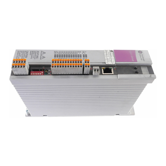
3.2 Layout The following shows the layout, with the corresponding positions of plugs and terminals. To aid orientation, the connectors and terminals are labelled by abbreviations. Illustration 13.1 YukonDrive® layout D1, D2 T1, T2 Software ratig plate Hardware rating plate Table 13.2 Key to YukonDrive®... -
Page 14: Connection Diagram
3.3 Connection diagram Illustration 14.2 Connection diagram Motor D1, D2 DC link T1, T2 Braking resistor Service Ethernet interface Option 2 Control ISA00+ Analog setpoint 1 Encoder ISA00- ISA01+ Analog setpoint 2 ISA01- +24V DC against I/O-GND ISD00 ISD01 Resolver ISD02 ISD03 ISD04... - Page 15 Table 15.1 Key to Connection diagram Designation Function Page D1, D2 7-Segmentanzeige Device status display see p. 42 T1, T2 Pushbuttons Service functions see p. 42 Motor, braking resistor and connection for measurement of DC see p. 27 Power connection link voltage +24 V DC supply voltage for control electronics of drive see p.
-
Page 16: Effective Emc Installation
3.4 Effective EMC installation 3.4.1 Interference immunity of drive controllers Attention! This is a restricted availability product in accordance with IEC 61800-3. This product may cause radio interference in domestic environments; in such cases the operator may need to take appropriate countermeasures. External radio frequency interference (RFI) suppression filters (EMCxxx) are available for the drive controllers. - Page 17 Detail 1: Motor cable Illustration 17.1 Specimen setup - Detail 1: Motor cable At the motor connection (X1) of the YukonDrive® note the following points: • Secure one of the two supplied shield connection plates by the screw to the mount on the top of the unit. Ensure the plate contacts across a wide area with the heat sink of the YukonDrive®...
- Page 18 Detail 3: Mains filter and mains connection Illustration 18.1 Specimen setup - Detail 3: mains filter and mains connection At the output of the mains filter and at the AC mains con- nection (X3): • Connect the wire strands at the output of the mains filter directly to the AC mains connection (X3) of the YukonDrive®.
-
Page 19: Protective Conductor Connection
3.5 Protective conductor connection Table 19.1 PE-mains connection Step Action to DIN EN 61800-5-1 Ground each of the drive controllers! Rules for the PE terminal as leakage current >3.5 in star configuration and across a Connect terminal mA): Use protective conductors with the same wide area to the PE rail (main ground) in the switch cabinet. -
Page 20: Electrical Isolation Method
3.6 Electrical isolation method The control electronics, with its logic (μP), the encoder terminals and the inputs and outputs, are electrically isolated from the power section (power supply/DC-link). All control terminals are designed as safety extra-low voltage/ protective extra-low voltage (SELV/PELV) circuits and must only be operated with such SELV/PELV voltages, as per the relevant specification. -
Page 21: Connection Of Supply Voltages
3.7 Connection of supply voltages The voltage supply to the YukonDrive® is separate for the control and power sections. The control supply should always be connected first, so that the device can be parameterized with DriveManager 5 and, above all, set to the correct power supply. -
Page 22: Connection Of Mains Supply, Bg2 And Bg3
3.7.2 Connection of mains supply, BG2 and BG3 Note: Before commissioning, the value of the connected mains voltage must be set on the drive controller (factory setting = 3 x 230 V AC /3 x 400 V AC). Illustration 22.1 BG2 and BG3 mains supply connection 3 x 230 V (YukonDrive®-10x1) or 3 x 400 V (YukonDrive®-10x2) depending on device design BG2 and BG3 3-phase... -
Page 23: Mains Supply Connection, Bg4
3.7.3 Mains supply connection, BG4 Note: Before commissioning, the value of the connected mains voltage must be set on the drive controller (factory setting = 3 x 230 V AC /3 x 400 V AC). Illustration 23.1 BG4 mains supply connection 3 x 230 V (YukonDrive®-1041) or 3 x 400 V (YukonDrive®-1042) depending on device design 3-phase system... - Page 24 Attention! If local regulations require the installation of a residual current operated protective device, the following applies: In case of a fault the drive controller is able to generate d.c. leak currents without zero crossing. Drive controllers there fore must only be operated with RCDs ) type B for a.c.
-
Page 25: Control Connections
3.8 Control connections Table 25.1 Step Action Comment Check whether a complete device setup is already available, i.e. whether the drive has already been configured. If this is the case, a special control terminal assignment applies. Please contact your project engineer to obtain the terminal assignment! Initial commissioning Choose a terminal assignment Ground the cable shields over a wide area at both... -
Page 26: Specification Of Control Connections
3.8.1 Specification of control connections Table 26.1 Specification of control connections X4 Bez. Specification El.isolation Analog inputs ISA0+ X4/3 = ±10 V DC ISA0- X4/4 Resolution 12 Bit; R ca. 101 kΩ ISA1+ X4/5 Terminal scan cycle in “IP mode” = 125 μs, otherwise = 1 ms ISA1- X4/6 Tolerance: U ±1 % of the measuring range end value. - Page 27 Table 27.1 Specification of control connections X4 Bez. Specification P.-Trennung STO „Safe Torque Off“ • „Request STO“ input = Low level • OSSD-capable ISDSH X4/22 • Switching level Low/High: <4,8 V / >18 V (STO) • = +24 V DC +20 % IN max •...
-
Page 28: Connection Of Motor Brake X13
Option 2 can be factory-configured with various technology options. Additional or special encoders can be evaluated with it for example. You will find all available options in the Harmonic Drive® catalogue. The Operating Manuals for the respective options provide detailed information on commissioning. -
Page 29: Motor- And Encoder Connection
The motor connection can be achieved by connector X1 on top of the device. All encoder connections are located on the top of the unit. Please use the ready-made cable sets from Harmonic Drive AG to connect motor and encoder. Following cable sets are availabe at the moment: Table 29.1 Cable sets... -
Page 30: Resolver Connection X6
3.12.1 Resolver connection X6 A resolver is connected to slot X6 (9-pin D-Sub female). Table 30.1 Pin assignment, X6-resolver connection Ill. X6/Pin Function Sin+ / (S2) analog differential input track A Refsin / (S4) analog differential input track A Cos+ / (S1) analog differential input track B Supply voltage 5 ... -
Page 31: Motor Connection
Table 31.1 Pin assignment, X7-encoder connection Absolute encod- Absolute Function Ill. X7/Pin ers SSI/EnDat encoder Sin/Cos and TTL 2.1/2.2 HIPERFACE® A– A– REFCOS +COS The sum of the +5 V, ±5 % at 7 to 12 V / currents tapped I_OUT_MAX=250 mA controlled, (typ. -
Page 32: Connection Of Harmonic Drive® Servo Motors And -Actuators
3.13.1 Connection of Harmonic Drive® Servo motors and -actuators Illustration 32.1 Connection of motor Motor DC link Braking resistor Option 2 Encoder Resolver Front 24V DC supply for brake OSD03 2 Brake (+) Brake (-) 1) 2) 1003370 05/2016 V01... - Page 33 Table 33.1 1) Confirguration of motor cable cores 5,6,7 and 8 Motor cable Configuration FHA-C CHA-A LynxDrive-C Core no. CHM-A Plug connection type:L Winding: H/L Winding: H Brake + Brake + Brake - Brake - N.C. Brake + N.C. Brake - Attention: For security reasons the connection of PTC has to be made via X5! 2) Brake control can also be made external (e.g.
-
Page 34: Switching In The Motor Cable
3.13.2 Switching in the motor cable Attention! Switching in the motor cable must take place with the power cut and the power stage disabled, as otherwise problems such as burned-off contactor contacts may occur. In order to ensure unpowered switch-on, you must make sure that the contacts of the motor contactor are closed before the drive controller power stage is enabled. - Page 35 Table 35.1 Data of the integrated braking resistor braking chopper switch-on Device Resistance [Ohm] Peak performance [W] threshold [VDC] YukonDrive®-1021-xxx YukonDrive®-1022-xxx 7500 based on 3 x 400 V mains voltage If the drive is not permanently operated at its power limit, the saved power dissipation of the drive can be used as braking power.
-
Page 36: Connection Of An External Braking Resistor
3.14.3 Connection of an external braking resistor Attention! • Be sure to follow the installation instructions for the external braking resistor. • The temperature sensor (bimetal switch) on the braking resistor must be wired in such a way that the power stage is deactivated and the connected drive controller is disconnected from the mains supply if the braking resistor overheats. -
Page 37: Commissioning
4. Commissioning 4.1 Notes for operation Attention! • Safety instructions Observe the safety instructions set out in section 1 during operation. • During operation, be sure to avoid ... – penetration of the device by foreign bodies or damp; – aggressive or conductive substances in the immediate vicinity; –... -
Page 38: Connecting The Pc And Drive Controller
In this case it must be ensured that the test will not cause any damage to the system! Pay particular attention to the limitations of the travel range. Please note that you yourself are responsible for safe operation. Harmonic Drive AG cannot accept liability for any damage incurred. - Page 39 • Destruction of the motor! – Some motors are intended for operation on the drive controller. Direct connection to the mains supply may destroy the motor. – The motor surfaces may become extremely hot. Temperature-sensitive items should therefore not be placed on top of or attached to the motors.
-
Page 40: Serial Commissioning
Display readout after drive start-up Table 40.1 Display D1/D2 during motor activation Action Reaction Explanation “STO” and power stage Ready for start Power stage ready “ENPO” enabled Attention! Make sure before the next step, “Start enable”, to preset a plausible setpoint value, because the presetting ist trans- ferred directly to the drive when motor control starts. -
Page 41: Functions Of Buttons T1 And T2
4.4.1 Functions of buttons T1 and T2 By way of the keypad the different menus are activated and the relevant functions controlled. Table 41.1 Functions of buttons T1 and T2 Button Function Comments T1 (left) Activate menu (quit device state display) Button T1 can be held down for any length of time, as the display Scroll through menus/submenus merely scrolls through the available menu items at the respective... -
Page 42: Parameters Menu (Pa)
4.4.3 Parameters menu (PA) On the Parameters menu the device settings can be reset to their factory defaults. Table 42.1 Parameters menu Menu level Para- Value Meaning Explanation meter range Parameter reset Reset device settings to factory defaults Error numbers A failed user action is indicated by an error message. - Page 43 Example configuration of subnet mask In this example the subnet mask is changed from 255.255.255.0 to 122.255.255.0. Note: Changes on the IP Address menu are only saved when the control electronics are subsequently restarted. Illustration 43.1 Example configuration of subnet mask Press button Tx (X = 1, 2) repeatedly until desired menu...
-
Page 44: Field Bus Adress Menu (Fb)
4.4.5 Field bus adress menu (Fb) The functions available under this menu item depend on the device expansion option. For detailed information refer to the relevant specification. Table 44.1 Field bus address menu Menu level Para- Value Meaning Explanation meter range 00..xx Example configuration of field bus address (only when field bus... -
Page 45: Diagnostics
5. Diagnostics The device states and error displays are indicated on the device by way of the 7-segment display of the integrated operator control unit. 5.1 Device states Table 45.1 Device states Anzeige System state Device in reset state Self-initialization on device start up Not ready to switch on (no DC-link voltage) Start inhibit (DC link OK, power stage not ready) Ready (power stage ready) -
Page 46: Error Codes
5.3 Error codes Note: For detailed information on the error codes and on error management refer to the YukonDrive® User Manual. 5.4 Helpline/Support & Service Our Technical Customer Service can provide you with fast, targeted assistance if you have any technical queries relat- ing to project planning or commissioning of the drive unit. -
Page 47: Appendix
A. Appendix A.1 Current capacity of servocontrollers The maximum permissible servo controller output current and the peak current are dependent on the mains voltage, the motor cable length, the power stage switching frequency and the ambient temperature. If the conditions change, the maximum permissible current capacity of the servo controllers also changes. - Page 48 YukonDrive® for 3 x 400/460/480 V Table 48.1 Rated current and peak current, BG2 to BG4 (3 x 400/460/480 V AC) Switching Rated current Peak current Ambient frequency tempera- of power 200 % (2 I 300 % (3 I ture Device stage for time...
-
Page 49: Yukondrive® Technical Data
A.2 YukonDrive® technical data Table 49.1 technical data YukonDrive® - 1021/-1031/-1041 Designation -1021 -1031 -1041 Technical data Output. motor side Voltage 3-phase U Netz Effective continuous current (l 5.9 A Peak current (A see table 44.1 and 44.2 Rotating field frequency 0 ... -
Page 50: Ambient Conditions
Table 50.1 technical data YukonDrive® -1022/ -1032/ -1042 Designation -1022 -1032 -1042 Technical data Output. motor side Voltage 3-phase U Netz Effective continuous current (l 3.5 A 6.5 A 10.5 A 19.5 A Peak current (A Rotating field frequency 0 ... 400 Hz Switching frequency of power stage 4. - Page 51 Table 51.1 YukonDrive® climatic conditions Climatic conditions YukonDrive® as per EN 61800-2, IEC 60721-3-2 class 2K3 in transit Temperature -25 °C to +70 °C Relative humidity 95 % at max. +55 °C as per EN 61800-2, IEC 60721-3-1 class 1K3 and 1K4 in storage Temperature -25 °C to +55 °C...
-
Page 52: Yukondrive® Ul Certification
A.4 YukonDrive® UL certification The devices are certified according to UL508C. The following conditions have to be observed: Use in systems with a maximum overvoltage category III. Use in a maximum pollution degree 2 environment only. Multiple rated equipment. For details see tables in chapter A.1, A.2 and A.3 in this manual. Use UL-certified 60/75°C copper conductors only. - Page 53 Germany Harmonic Drive AG info@harmonicdrive.de Subject to technical changes. T +49 6431 5008-0 Hoenbergstraße 14 www.harmonicdrive.de F +49 6431 5008-119 65555 Limburg/Lahn...
Need help?
Do you have a question about the YukonDrive-1021 and is the answer not in the manual?
Questions and answers