Table of Contents
Advertisement
Quick Links
Advertisement
Table of Contents

Related Manuals for Harmonic Drive SHA Series


Summary of Contents for Harmonic Drive SHA Series
- Page 1 AC Servo Actuator SHA SG and CG series manual ISO14001 (Hotaka plant) ISO9001...
- Page 2 Introduction Introduction Thank you for purchasing our SHA series AC Servo Actuator. • Improper handling or use of this product may result in an accident or reduced life of the product. Read this document carefully and use the product correctly so that the product can be used safely for many years to come.
-
Page 3: Safety Guide
SAFETY GUIDE SAFETY GUIDE To use this actuator safely and correctly, be sure to read SAFETY GUIDE and other parts of this manual carefully. It is important to fully understand the information provided herein before using the actuator. NOTATION Important safety information you must note is provided herein. Be sure to observe these instructions. Indicates a potentially hazardous situation, which, if not avoided, could result in death or serious personal injury. -
Page 4: Introduction
SAFETY GUIDE SAFETY NOTE ITEMS YOU SHOULD NOTE WHEN USING THE ACTUATOR • PRECAUTIONS FOR ACTUATORS AT THE APPLICATION DESIGN PHASE Always use under followings conditions. The actuator is designed to be used indoors. Observe the following conditions: ・ Ambient temperature: 0℃ to 40℃ CAUTION ・... - Page 5 SAFETY GUIDE ITEMS YOU SHOULD NOTE WHEN USING THE DRIVER CAUTIONS RELATED TO THE DESIGN Always use drivers under followings conditions. The driver generates heat. Use under the following conditions while paying careful attention to the heat radiation. CAUTION ・...
- Page 6 SAFETY GUIDE Do not make a voltage resistance test. ・ Failure to observe this caution may result in damage of the control unit. ・ Please consult our sales office, if you intent to use a voltage resistance CAUTION test. Do not operate control units by means of power ON/OFF switching.
-
Page 7: Table Of Contents
Contents Introduction ......................4 SAFETY GUIDE ...................... 3 NOTATION ......................3 LIMITATION OF APPLICATIONS ................3 SAFETY NOTE ...................... 4 Contents ........................7 Overview 1-1 Overview ......................13 1-2 Model………………………………………………………………………………..14 1-3 Drivers and extension cables ................ 15 1-4 Specifications ....................16 1-5 Motor shaft brake .................. - Page 8 1-1 Overview Selection guidelines 2-1 SHA series selection ..................71 Allowable load moment of inertia ................71 2-2 Change in load moment of inertia ..............75 2-3 Verifying and examining load weights ..............76 Maximum load moment load ................. 77 Verifying life ......................
- Page 9 1-1 Overview 1 Overview of the SHA series 放熱板: 3 5 0 * 3 5 0 * 1 8 Radiation plate: 350*350*18 1 5 0 1 2 5 Motion range during 1 0 0 acceleration and 加減速運転領域 deceleration 50% duty range 5 0 % デューティ領域...
- Page 10 1-1 Overview SG/HP type Model SHA20A Item (1) Output at point A (2) Voltage at point A (3) Allowable continuous current (4) Speed at point A (5) Frequency at point A (6) Allowable range ℃ temperature - (7) Number of phase Model SHA25A SHA25A (Motor input voltage 200V)
- Page 11 1-1 Overview CG type Model SHA20A Item (1) Output at point A (2) Voltage at point A (3) Allowable continuous current (4) Speed at point A 29.5 (5) Frequency at point A (6) Allowable range ℃ temperature - (7) Number of phase Model SHA25A(Motor input voltage SHA25A((Motor input...
-
Page 12: Overview
1-1 Overview Chapter 1 Overview This chapter explains the features, functions and specifications of the actuator. 1-1 Overview ············································································· 13 1-2 Model ················································································· 14 1-3 Drivers and extension cables ··················································· 15 1-4 Specifications ······································································· 16 1-5 Motor shaft brake ·································································· 25 1-6 External dimensions ······························································... -
Page 13: Overview
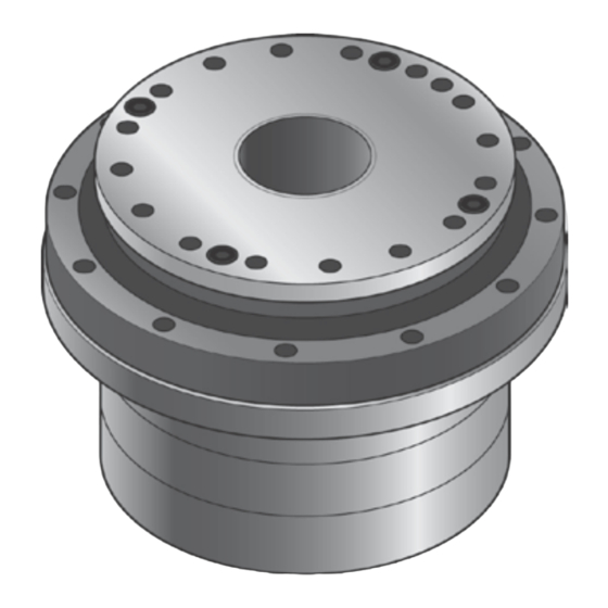
Overview The SHA series of AC Servo Actuators provide high torque and high accuracy rotary motion. These AC Servo Actuators are each composed of a Harmonic Drive® speed reducer for precise control and a flat, high performance AC servo motor with an integral absolute multi-turn encoder. -
Page 14: Model
1-2 Model Model Model numbers for the SHA series actuators and how to interpret them are explained below. Examples of standard models - - - - S17b - - - - (15) (10) (11) (12) (13) (14) (1) Model: SHA series actuator... -
Page 15: Drivers And Extension Cables
1-3 Drivers and extension cables Drivers and extension cables The proper combination of SHA actuators, drivers, and extension cables are as follows: SHA20A SHA25A SHA32A SHA40A SHA58A SHA65A REL230-36 REL Servo Drive REL-230-18 REL-230-18 REL 230-40 HA-800A-6 D/E - HA-800A- HA-800A- 3D/E-200 HA-800 Standard... -
Page 16: Specifications
1-4 Specifications Specifications SG type SHA20A Model Item REL-230-18 Servo Drive HA-800□-3D/E-200 Max. torque kgf・m 10.9 11.5 12.2 Allowable continuous *1*2 torque kgf・m 117.6 74.1 59.4 49.6 37.3 Max. rotational speed Nm/A 16.5 Torque constant kgf・m/A Max. current Allowable continuous *1*2 current EMF constant... - Page 17 1-4 Specifications SG/HP type SHA25A Model SHA25A (Motor input voltage 200V) (Motor input voltage 100V) Item REL-230-18 REL-230-18 REL-230-36 Servo Drive HA-800□-6D/E-100 HA-800□-3D/E-200 Max. torque kgf・m 18.2 20.8 22.1 23.4 18.2 20.8 22.1 23.4 Allowable continuous kgf・m 0.92 *1*2 torque Max.
- Page 18 1-4 Specifications SG/HP type SHA32A Model Item REL-230-18, REL-230-36 Servo Drive HA-800□-6D/E-200 Max. torque kgf・m 28.7 40.3 44.2 46.8 49.4 Allowable continuous kgf・m 15.6 18.2 18.2 18.2 *1*2 torque Max. rotational 436.4 94.1 59.3 47.5 39.7 29.8 speed Nm/A Torque constant kgf・...
- Page 19 1-4 Specifications SG type Model SHA40A Item REL-230-36, REL-230-40 Servo Drive HA-800□-6D/E-200 HA-800□-24D/E-200 Max. torque kgf・m 34.7 57.1 81.8 85.8 53.4 68.9 75.3 81.8 85.8 Allowable continuous *2*3 torque kgf・m 16.1 20.2 24.2 32.3 16.3 26.8 33.7 Max. rotational speed 78.4 49.4 39.6...
- Page 20 1-4 Specifications SG type SHA58A SHA65A Model Item Servo Drive HA-800□-24D/E-200 HA-800□-24D/E-200 1924 2067 2236 2392 2400 2990 3263 3419 Max. torque kgf・m Allowable 1149 1236 1236 continuous kgf・m *1*2 torque Max. rotational 37.0 29.7 24.8 18.6 34.6 27.7 23.1 17.4 speed Nm/A...
- Page 21 1-4 Specifications CG type SHA20A Actuator Model Item REL-230-18 Servo Drive HA-800□-3D/E-200 Max. torque kgf・m 10.9 11.5 12.2 Allowable continuous *1*2 torque kgf・m Max. rotational speed 37.5 Nm/A Torque constant kgf・m/A Max. current Allowable continuous *1*2 current EMF constant V/(rpm) Phase resistance Ω...
- Page 22 1-4 Specifications CG type Model SHA25A(Motor input voltage 100V) SHA25A(Motor input voltage 200V) Item REL-230-18 REL-230-18 REL-230-36 REL-230-36 Servo Drive HA-800□-6D/E-100 HA-800□-3D/E-200 Max. torque kgf・m 18.2 20.8 22.1 23.4 18.2 20.8 22.1 23.4 Allowable continuous *1*2 torque kgf・m Max. rotational speed 46.7 Nm/A 10.9...
- Page 23 1-4 Specifications CG type Model SHA32A Item REL-230-18 Servo Drive REL-230-36 HA-800□-6D/E-200 Max. torque kgf・m 28.7 40.3 44.2 46.8 49.4 Allowable continuous *1*2 torque kgf・m 15.4 18.2 18.2 18.2 Max. rotational speed Nm/A Torque constant kgf・ Max. current 17.7 15.4 13.7 12.2 Allowable continuous...
- Page 24 1-4 Specifications CG type SHA40A Model/Ratio Item REL-230-36, REL-230-40 REL-230-36, REL-230-40 Combined driver HA-800□-6D/E-200 HA-800□-24D/E-200 Max. torque kgf・m 34.0 55.9 70.0 81.8 85.8 53.4 68.9 75.3 81.8 85.8 Allowable continuous *2*3 torque kgf・m 15.9 20.0 24.0 32.1 16.0 26.5 33.3 Max.
-
Page 25: Motor Shaft Brake
1-5 Motor shaft brake Motor shaft brake The brake is used to hold the motor shaft in place when the power is turned off. With smaller sizes (SHA25A, 32A), the actuator's built-in circuit controls the voltage supplied to the brake in order to reduce the power consumption while the brake is actuated. - Page 26 1-5 Motor shaft brake Model SHA40A SHA58A Item Type Dry non-excitation actuation type (without power-saving control) Brake excitation voltage DC24V ± 10% (no polarity) Current consumption during suction (at 20℃) Current consumption Same as current consumption during suction during holding (at 20℃) 1220 1520 1820...
- Page 27 1-5 Motor shaft brake Model SHA32A SHA40A Item Dry non-excitation actuation type (with power- Dry non-excitation actuation type (without Type saving control) power-saving control) Brake excitation DC24V±10%(no polarity) voltage Current consumption during suction (at 20℃) Current consumption during holding (at Same as current consumption during suction 20℃) Holding torque...
-
Page 28: External Dimensions
1-6 External dimensions External dimensions SHA20A-SG Unit: mm 付... - Page 29 1-6 External dimensions SHA20A-CG Unit: mm 付...
- Page 30 1-6 External dimensions SHA25A-HP Unit: mm 付...
- Page 31 1-6 External dimensions SHA25A-SG Unit: mm 付...
- Page 32 1-6 External dimensions SHA25A-CG Unit: mm 付...
- Page 33 1-6 External dimensions SHA32A-HP Unit: mm 付...
- Page 34 1-6 External dimensions SHA32A-SG Unit: mm 付...
- Page 35 1-6 External dimensions SHA32A-CG Unit: mm 付...
- Page 36 1-6 External dimensions SHA40A-SG Unit: mm 付...
- Page 37 1-6 External dimensions SHA40A-CG Unit: mm 付...
- Page 38 1-6 External dimensions SHA58A-SG Unit: mm 付...
- Page 39 1-6 External dimensions SHA65A-SG Unit: mm 付...
-
Page 40: Mechanical Accuracy
1-7 Mechanical accuracy Mechanical accuracy SHA series mechanical accuracy of the output shaft and mounting flange: SG/HP type unit: mm Accuracy items SHA20A SHA25A SHA32A SHA40A SHA58A SHA65A 0.035 0.040 1. Output shaft surface runout 0.030 0.045 0.050 0.050 (0.020)... - Page 41 1-7 Mechanical accuracy The reported values are measured as follows: Output shaft surface runout The indicator is fixed and measures the axial run-out (T.I.R.) of the outermost circumference of the output shaft for one revolution. Output shaft radial run-out The indicator is fixed and measures the radial run-out (T.I.R.) of the output shaft for one revolution.
-
Page 42: One-Way Positional Accuracy
(1/ratio) and typically becomes negligible at the output. Therefore most of the error is represented by the transmission error of the Harmonic Drive gear itself. The one-way positional accuracy is shown in the table below: 付... -
Page 43: Repeatability (Cg Type)
1-8 One-Way Positional accuracy Repeatability (CG type) The repeatability is measured by moving to a given theoretical position seven times, each time approaching from the same direction. The actual position of the output shaft is measured each time and repeatability is calculated as the 1/2 of the maximum difference of the seven data points. -
Page 44: Encoder Specifications (Absolute Encoder)
Encoder specifications (Absolute encoder) The absolute encoder used in the SHA series is a multi-turn magnetic absolute encoder. This encoder consists of 17 bit single turn absolute encoder and a 16 bit cumulative counter for detecting the number of total revolutions. - Page 45 1-9 Encoder specifications (Absolute encoder) Transfer of encoder data Data is transferred via bi-directional communication in a normal condition while power is supplied. When the driver control power supply is turned OFF and the driver enters the battery backup mode, communication stops. Output shaft single revolution absolute model (Option) With the standard actuator, when it continues to rotate in just one direction, the absolute encoder eventually exceeds the number of revolutions that can be detected with multi-revolution detection and it becomes impossible...
-
Page 46: Output Stiffness
1-10 Output Stiffness 1-10 Output Stiffness Moment stiffness The moment stiffness refers to the torsional stiffness when a moment load is applied to the output shaft of the actuator (shown in the figure). For example, when a load is applied to the end of an arm attached on the output shaft of the actuator, the face of the output shaft of the actuator tilts in proportion to the moment load. -
Page 47: Torsional Stiffness
This [torque vs. torsional angle] diagram, typically follows a loop of 0-A-B-A’-B’-A. The torsional stiffness of the SHA series actuator is expressed by the slope of this [torque vs. torsional angle diagram] representing a spring constant (unit: Nm/rad). - Page 48 1-10 Output Stiffness Model SHA58A SHA65A Reduction ratio 81:1 or more 81:1 or more kgf・m Nm/rad kgf・m/arc min θ1 arc min kgf・m Nm/rad kgf・m/arc min 11.1 11.3 θ2 arc min Nm/rad kgf・m/arc min The table below shows reference torque values calculated for different torsional angle. (Unit: N・m) Model SHA20A...
-
Page 49: Torsional Stiffness (Ratio 11: Hpf)
1-10 Output Stiffness Torsional Stiffness (Ratio 11: HPF) If a torque is applied to the output shaft of the actuator with the input locked, the output shaft will torsional deflect roughly in proportion to the torque. When the values for torque are gradually changed in sequence from (1) Rated output torque in the positive rotation direction→(2) zero→(3) Rated output torque in the negative rotation direction→(4) zero→(5) Rated output torque in the positive rotation direction, the values follow a loop (1)→(2)→... -
Page 50: Direction Of Rotation
Forward command (FWD command pulse) is given to a SHA series actuator from a HA-800 driver This rotation direction can be changed on the HA-800 driver by selecting [SP50: Command polarity setting] under [System parameter mode 3]. -
Page 51: Shock Resistance
1-12 Shock resistance 1-12 Shock resistance The actuator can withstand a 300 m/s shock in all directions (up/down, left/right, and front/rear): Impact acceleration: 300 m/s In our shock resistance test, the actuator is tested 3 times in each direction. Actuator operation is not guaranteed in applications where impact exceeding the above value is constantly applied. -
Page 52: Vibration Resistance
1-13 Vibration resistance 1-13 Vibration resistance The actuator can withstand a 25 m/s vibration acceleration (frequency 10 to 400 Hz) in all directions (up/down, left/right, and front/rear): Vibration acceleration: 25 m/s (frequency: 10 to 400Hz) In our test, the actuator is tested for 2 hours in each direction at a vibration frequency sweep period of 10 minutes. -
Page 53: Operable Range
Operable range The graph on the next page indicates the torque/speed operating range for the SHA actuators (combined with a HA-800 driver) is selected. For details, refer to [Chapter 2 SHA series selection]. 1. Continuous motion range The range allows continuous operation of the actuator. - Page 54 1-14 Operable range SHA20A SG ■SHA20A51SG ■SHA20A81SG ■SHA20A101SG ■SHA20A121SG ■SHA20A161SG 付...
- Page 55 1-14 Operable range SHA25A SG (Specifications for motor input voltage of 100V) ■SHA25A51SG ■SHA25A81SG 放熱板:350*350*18 Radiation plate: 350*350*18 mm 放熱板:350*350*18 Radiation plate: 350*350*18 mm Motion range during Motion range during 加減速運転領域 加減速運転領域 acceleration and acceleration and deceleration deceleration 50%デュー ティ領域 50% duty motion range 50%デュー...
- Page 56 1-14 Operable range SG/HP SHA25A (Specifications for motor input voltage of 200V) ■SHA25A11HP ■SHA25A51SG 放熱板:350*350*18 mm Radiation plate: 350*350*18 mm 放熱板: 3 5 0 * 3 5 0 * 1 8 Radiation plate: 350*350*18 mm 1 5 0 1 2 5 Motion range during acceleration and deceleration...
- Page 57 1-14 Operable range SG/HP SHA32A ■SHA32A11HP ■SHA32A51SG Radiation plate: 400*400*20 mm 放熱板:400*400*20 mm Radiation plate: 400*400*20 mm 放熱板:400*4 00*20 Motion range during acceleration and Motion range during 加減速運転領域 deceleration acceleration and deceleration 50%デューティ領域 50% duty motion range 50% duty motion range Continuous motion Continuous...
- Page 58 1-14 Operable range SHA40A SG ■SHA40A51SG /HA-800-6D/E ■SHA40A81SG/HA-800-6D/E 放熱板:500*500*25 放熱板: 5 0 0 * 5 0 0 * 2 5 Radiation plate: 500*500*25 Radiation plate: 500*500*25 加減速運転領域 Motion range during acceleration and deceleration Motion range during acceleration 加減速運転領域 and deceleration 5 0 % デューティ領域...
- Page 59 1-14 Operable range SHA-40A SG ■SHA40A51SG/HA-800-24D/E ■SHA40A81SG/HA-800-24D/E 放熱板: 5 0 0 * 5 0 0 * 2 5 Radiation plate: 500*500*25 mm 放熱板: 5 0 0 * 5 0 0 * 2 5 Radiation plate: 500*500*25 mm Motion range during acceleration Motion range during 加減速運転領域...
- Page 60 1-14 Operable range SHA58A SG ■SHA58A81SG ■SHA58A101SG 放熱板:650*650*30 放熱板:650*650*30 Radiation plate: 650*650*30 mm Radiation plate: 650*650*30 mm 2500 2000 1750 2000 1500 Motion range during acceleration 加減速運転領域 Motion range during acceleration and deceleration 加減速運転領域 and deceleration 1250 1500 1000 50%デューティ領域 50% duty motion range 50%デューティ領域...
- Page 61 1-14 Operable range SHA65A SG ■SHA65A81SG ■SHA65A101SG 放熱板: 6 5 0 * 6 5 0 * 3 0 放熱板:650*650*30 Radiation plate: 650*650*30 mm Radiation plate: 650*650*30 mm 3 0 0 0 3500 3000 2 5 0 0 2500 Motion range during acceleration 加減速運転領域...
- Page 62 1-14 Operable range SHA20A CG ■SHA20A50CG ■SHA20A80CG Radiation plate: 320*320*16 mm Radiation plate: 320*320*16 mm Motion range during acceleration Motion range during acceleration and deceleration and deceleration 50% duty motion 50% duty motion range range Continuous Continuous motion range motion range Rotation speed [rpm] Rotation speed [rpm] ■SHA20A100CG...
- Page 63 1-14 Operable range SHA25A CG (Motor input voltage 100V) ■SHA25A50CG ■SHA25A80CG Radiation plate: 350*350*18 mm Radiation plate: 350*350*18mm Motion range during acceleration Motion range during and deceleration acceleration and deceleration 50% duty motion range 50% duty motion range Continuous Continuous motion 連続使用領域...
- Page 64 1-14 Operable range SHA25A CG (Motor input voltage 200V) ■SHA25A50CG ■SHA25A80CG Radiation plate: 350*350*18 mm Radiation plate: 350*350*18 mm Motion range during acceleration Motion range during acceleration and deceleration and deceleration 50% duty motion range 50% duty motion range Continuous motion Continuous motion 連続使用領域...
- Page 65 1-14 Operable range SHA32A CG ■SHA32A50CG ■SHA32A80CG Radiation plate: 400*400*20 mm Radiation plate: 400*400*20 mm Motion range during acceleration Motion range during acceleration and deceleration and deceleration 50% duty motion range 50% duty motion range Continuous motion Continuous motion 連続使用領域 連続使用領域...
- Page 66 1-14 Operable range SHA40A CG ■SHA40A50CG/HA-800-6D/E ■SHA40A80CG/HA-800-6D/E Radiation plate: 500*500*25 mm Radiation plate: 500*500*25 mm Motion range during acceleration and deceleration Motion range during acceleration and deceleration 50% duty motion range 50% duty motion range Continuous motion Continuous motion range range Rotation speed [rpm] Rotation speed [rpm]...
- Page 67 1-14 Operable range SHA40A CG ■SHA40A50CG/HA-800-24D/E ■SHA40A80CG/HA-800-24D/E Radiation plate: 500*500*25 mm Radiation plate: 500*500*25 mm Motion range during acceleration Motion range during acceleration and deceleration and deceleration 50% duty motion range 50% duty motion range Continuous motion range 連続使用領域 Continuous 連続使用領域...
-
Page 68: Cable Specifications
1-15 Cable specifications 1-15 Cable specifications The following tables show specifications of the motor and encoder cables of the SHA series actuators. Motor cable specifications Size 20, 25, 32, 40 Name Pin number Color Without brake With brake Motor phase-U... -
Page 69: Encoder Cable Specifications
1-15 Cable specifications Encoder cable specifications Size 20, 25, 32, 40 Pin number Signal name Remarks Color Power supply input +5V Black GND(Vcc) Power supply input 0V (GND) Yellow Serial signal differential output (+) Blue Serial signal differential output (-) -... -
Page 70: Selection Guidelines
Chapter 2 Selection guidelines This chapter explains how to select the right SHA series actuator. 2-1 SHA series selection ······························································ 71 2-2 Change in load inertia moment ················································ 75 2-3 Verifying and examining load weights ········································ 76 2-4 Examining operating status ····················································· 80... -
Page 71: Sha Series Selection
SHA series selection Allowable load moment of inertia To achieve high accuracy performance, select a SHA series actuator where the allowable moment of inertia for the actuator is not exceeded. Note: The recommended values in the graphs below should be followed if you wish to shorten the transient vibration period during positioning moves or operate the actuator at a constant speed in a stable manner. - Page 72 2-1 SHA series selection CG type Allowable load inertia moment Max rotational speed (r/min) Allowable load inertia moment Max rotational speed (r/min) 付 When making a preliminary selection of the actuator, make certain that the moment of inertia and maximum speed do not exceed the allowable values shown on the following page.
- Page 73 2-1 SHA series selection SG/HP SHA20A Model Reduction ratio 51:1 81:1 101:1 121:1 161:1 Max. speed (rpm) 117.6 74.1 59.4 49.6 37.3 Actuator kg・m 0.23 0.58 0.91 inertia kgf・cm・s (without brake) Actuator kg・m 0.26 0.65 inertia (with kgf・cm・s brake) kg・m...
- Page 74 2-1 SHA series selection SHA65A Model Reduction ratio 81:1 101:1 121:1 161:1 Max. speed (rpm) 34.6 27.7 23.1 17.4 kg・m Actuator inertia kgf・cm・ 1120 1740 2500 4420 (without brake) kg・m Actuator inertia (with kgf・cm・ 1230 1910 2740 4850 brake) kg・m...
-
Page 75: Change In Load Moment Of Inertia
With the SHA series, the value of R increases from 50 to 161, which means that the value increases = 25,921. Then the ratio is Js'/Js ≒ 1. This means that SHA drive substantially from R = 2,500 to R systems are hardly affected by the load variation. -
Page 76: Verifying And Examining Load Weights
2-3 Verifying and examining load weights Verifying and examining load weights The SHA series actuator incorporates a precise cross roller bearing for directly supporting an external load (output flange). To demonstrate the full ability of the actuator, verify the maximum load moment load as well as the life and static safety coefficient of the cross roller bearing. -
Page 77: Maximum Load Moment Load
2-3 Verifying and examining load weights Maximum load moment load The formula below shows how to calculate the maximum load Actuator moment load (Mmax). Verify that the maximum load moment load (Mmax) is less than Load or equal to the allowable load (Mc). ◆... - Page 78 2-3 Verifying and examining load weights Radial load coefficient and axial load coefficient Determine the values of radial load coefficient (X) and axial load coefficient (Y) based on the condition below. Table 2: Radial load coefficient (X), axial load coefficient (Y) ◆...
-
Page 79: Verifying Static Safety Coefficients
2-3 Verifying and examining load weights Cross roller bearing life with oscillating motion Use formula (8) to calculate the cross roller bearing life against oscillating movement. ◆ Formula (8): Cross roller bearing life (oscillating) 10/3 × × ... -
Page 80: Examining Operating Conditions
Accordingly, examine whether or not the generated heat can be accommodated. The study is as follows: Calculate the actuator rotation speed Calculate the required rotation speed (rpm) of the load driven by the SHA series. For linear operation, use the rotation speed conversion formula below: Screw pitch (mm) -
Page 81: Load Torque Calculation
2-4 Examining operating conditions Load torque calculation Calculate the load torque as follows: Rotary motion The rotary torque for the rotating mass W on the ring Mass: W of radius r from the center of rotation is shown in the figure to the right. -
Page 82: Acceleration And Deceleration Time
2-4 Examining operating conditions Acceleration and deceleration time Calculate acceleration and deceleration times for the selected actuator. × π × × × Acceleration time: − × π × × × Deceleration time: × Rotation speed : Acceleration time : Deceleration time k: Acceleration reduction coefficient 1 to 1.5 The total positioning time may become shorter if the acceleration is lowered for the purpose... -
Page 83: Examining Effective Torque And Average Rotation Speed
2-4 Examining operating conditions Examining effective torque and average rotation speed One way to check if the heat generated from the actuator during operation would present a problem is to determine if the point of operation, determined by the effective torque and average rotation speed, is inside the continuous motion range explained in [1-14 Operable range]. - Page 84 2-4 Examining operating conditions (5) The figure on the right shows the point of operation determined by the effective torque and average rotation speed calculated above, plotted on the graph of operable range of SHA25A51, exceeding the continuous motion range. The conclusion is that this actuator cannot be operated continuously under these conditions.
-
Page 85: Installing The Sha Actuator
Chapter 3 Installing the SHA actuator The following explains the installation procedures of the actuators. 3-1 Receiving Inspection ······························································ 86 3-2 Notices on handling ······························································· 87 3-3 Location and installation ························································· 91... -
Page 86: Receiving Inspection
Confirm the actuator is what you ordered. The nameplate is found on the rear end face of the SHA series actuator. Check the TYPE field on the nameplate to confirm that it is indeed the model you have ordered. If any item is wrong, immediately contact the dealer. -
Page 87: Notices On Handling
Handle the SHA series actuator carefully by observing the notices specified below. (1) Do not apply any excessive force or impact, especially to the actuator's output shaft. (2) Do not put the SHA series actuator on a table, shelf, etc., where the CAUTION actuator could easily fall. - Page 88 3-2 Notices on handling SHA-CG assembly example Actuator fixing parts Actuator fixing parts Output shaft fixing parts Output shaft fixing parts Assembly example 3 Assembly example 4 Recommended tightening torque and transmission torque SG/HP type SHA20A SHA25A SHA32A Model Output Output Output...
-
Page 89: Precautions On Installation
When designing the assembly, take note that application of any abnormal or excessive force that causes deformation of the installation surface may result in performance drop. To demonstrate the excellent performance of the SHA series actuator fully, take note of the following points: Warping or deformation on the machine mounting surfaces ... -
Page 90: Use Of Positioning Pins
Use of positioning pins The SHA series SG type actuator has positioning pin holes in the output rotary unit and flange fixed to the actuator. The SHA series CG type has positioning pin holes only in the output rotary unit. -
Page 91: Location And Installation
3-3 Location and installation Location and installation Operating Environment The environmental conditions of the installation location for SHA series actuators must be as follows. Select an appropriate installation location and observe these conditions without fail. ◆ Operating temperature: 0 to 40℃... -
Page 92: Installation
3-3 Location and installation Installation The SHA series actuator drives mechanical load system at high accuracy. When installing the actuator, pay attention to precision and do not tap the actuator output part with a hammer, etc. The actuator houses an encoder. Excessive impact may damage the encoder. -
Page 93: Options
Chapter 4 Options This chapter explains the options available for the SHA series actuator. 4-1 Options ··············································································· 94... -
Page 94: Options
Options Options Origin and end limit sensors (option code: L) This option includes sensors that are directly connected to the output shaft on the rear of the actuator. Use this option if a mechanical origin is required (when the virtual origin of the absolute encoder is not sufficient) or you want to define an operation range as a safety measure. - Page 95 Options ●Outline drawing of the actuator with an optional stand 付...
- Page 96 Options ●Dimensions and installation specifications of the actuator with an optional stand Item Unit SHA20 SHA25 SHA32 SHA40 φ69 h7 0/-0.030 φ84 h7 0/-0.035 φ110 h7 0/-0.035 φ132 h7 0/-0.040 φ135 φ160 φ198 φ248 φ143 φ168 φ208 φ258 φ177 h7 0/-0.040 φ210 h7 0/-0.046 φ260 h7 0/-0.052 φ316 h7 0/-0.057...
-
Page 97: Extension Cables
Options Extension cables These extension cables are used to connect the SHA series actuators and HA-800 drivers. Two types of extension cables are available for motor (including brake wire) and absolute encoder. You must use an extension cable to connect your SHA series actuator and HA-800 driver. - Page 98 Options SHA 58, 65 EWD-MB**-D09-TMC Cable length (03 = 3m, 05 = 5m, 10 = 10m) [Actuator side] [Driver side] Cable length Outer diameter φ13.4 U: red V: white W: Black Brake: blue Waterproof cable clamp Brake: yellow PE: green/yellow Angle plug (Unit: mm) 付...
- Page 99 Options Absolute encoder extension cable: SHA 20, 25, 32, 40 EWD-S**-A08-3M14 Cable length (03 = 3m, 05 = 5m, 10 = 10m) (** in the model code indicates the cable length (3m, 5m, 10m). [Driver side] [Actuator side] Cable length Outer diameter φ8.4 (Unit: mm) ...
-
Page 100: Appendix
Options Appendix A-1 Unit conversion··································································· 101 A-2 Calculating inertia moment ···················································· 103 付... - Page 101 Unit conversion Unit conversion This manual employs SI system for units. Conversion factors between the SI system and other systems are as follows: (1)Length SI system Unit Factor 0.3048 0.0254 Unit Factor 3.281 39.37 SI system (2)Linear speed SI system Unit m/min ft./min...
- Page 102 Unit conversion (8)Angular acceleration SI system rad/s Unit deg/s deg/min Factor 0.01755 2.93x10 Unit deg/s deg/min Factor 57.3 3.44x10 SI system rad/s (9)Torque SI system N・m Unit kgf・m lb・ft lb・in oz・in Factor 9.81 1.356 0.1130 7.06x10 Unit kgf・m lb・ft lb・in oz・in Factor 0.102...
-
Page 103: Calculating Moment Of Inertia
Calculating moment of inertia Calculating moment of inertia Formula for moment of inertia and mass For cases where the center of gravity is coincident with the axis of rotation: The following table includes formulas to calculate mass and inertia moment. m : mass (kg), Ix, Iy, Iz: inertia moments which rotates around x-, y-, z-axes respectively (kg・m G : distance from end face of gravity center (m) ρ... - Page 104 Calculating moment of inertia Object form Mass, inertia, gravity center Object form Mass, inertia, gravity center Rhombus pillar Hexagonal pillar ρ ρ B√3 Ix = Isosceles triangle Right triangle pillar ABCρ...
-
Page 105: Moment Of Inertia Of A Cylinder
Calculating moment of inertia Moment of inertia of a cylinder The inertia moment of a cylinder Inertia moment (kgm Length (mm) may be obtained from the graphs to 1000 Inertia moment (specific gravity: 2.7) the right. 1000 Radius Length Apply the top graph to aluminum materials (specific gravity: 2.7) and bottom graph to steel materials 0.01... -
Page 106: Index
Extension cable ............ 99 Rotation direction..........51 External dimensions ..........29 S I SHA series selection..........73 Inertia moment ............ 106 Shock resistance ..........52 Inertia moment of a cylinder ....... 108 Specifications ............16 Installation ..........90, 94, 95 Static safety coefficient ......... - Page 108 All efforts have been made to assure that the information in this catalog is complete and accurate. However, Harmonic Drive LLC is not liable for any errors, omissions or inaccuracies in the reported data. Harmonic Drive LLC reserves the right to change the product specifications, for any reason, without prior notice.
- Page 109 Hoenbergstrasse, 14, D-6555 Chicago Office Limburg/Lahn Germany 137 N. Oak Park Ave. Suite 410, Oak Park, IL 60301 California Office 333 W. San Carlos St. Suite 1070, San Jose, CA 95110 Harmonic Drive is a registered trademark of Harmonic Drive LLC. 20190125...
Need help?
Do you have a question about the SHA Series and is the answer not in the manual?
Questions and answers