Harmonic Drive LynxDrive Series Manual
Ac servo actuators
Hide thumbs
Also See for LynxDrive Series:
- Assembly instructions manual (43 pages) ,
- Assembly instructions manual (113 pages)

Related Manuals for Harmonic Drive LynxDrive Series


Summary of Contents for Harmonic Drive LynxDrive Series
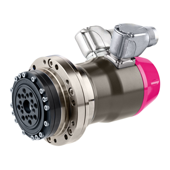
- Page 1 Engineering Data AC Servo Actuators LynxDrive® More information on our servo products can be found HERE!
-
Page 2: Table Of Contents
Contents General ..............................4 Description of Safety Alert Symbols ............................5 Disclaimer and Copyright ..............................5 Safety and Installation Instructions ....................6 Hazards ....................................6 Intended Purpose .................................. 7 Non Intended Purpose ................................7 Use in Special Application Areas ............................8 Declaration of Conformity ..............................8 2.5.1 Gears .................................. - Page 3 Actuator Data LynxDrive-50C .............................29 6.8.1 Technical Data ................................29 6.8.2 Moment of Inertia ..............................30 6.8.3 Technical Data Brake ............................... 30 6.8.4 Performance Characteristics ........................... 31 Dimensions ..................................32 6.10 Accuracy ....................................34 6.11 Torsional Stiffness................................34 6.12 Output Bearing ..................................35 6.12.1 Technical Data ................................35 6.12.2 Tolerances ................................35 6.13 Motor Feedback Systems ..............................36...
-
Page 4: General
For the configuration of drive systems using the products of Harmonic Drive AG, you may require additional documents. Documentation is provided for all products offered by Harmonic Drive AG and can be found in pdf format on the website. www.harmonicdrive.de Third-party systems Documentation for parts supplied by third party suppliers, associated with Harmonic Drive®... -
Page 5: Description Of Safety Alert Symbols
1.1 Description of Safety Alert Symbols Symbol Meaning Indicates an imminent hazardous situation. If this is not avoided, death or DANGER serious injury could occur. Indicates a possible hazard. Care should be taken or death or serious injury may WARNING result. -
Page 6: Safety And Installation Instructions
2. Safety and Installation Instructions Please take note of the information and instructions in this document. Specially designed models may differ in technical detail. If in doubt, we recommend to contact the manufacturer, giving the type designation and serial number for clarification. -
Page 7: Intended Purpose
The products may only be operated within the operating ranges and environmental conditions shown in the documentation (altitude, degree of predection, temperature range, etc). Before commissioning of plants and machinery including Harmonic Drive® Products, the compliance with the Machinery Directive must be established. -
Page 8: Use In Special Application Areas
The conformity to the EU directives of equipment, plant and machinery in which Harmonic Drive® Servo Actuators and Motors are installed must be provided by the user before taking the device into operation. -
Page 9: Technical Description
3. Technical Description Compact actuator with high corrosion protection The servo drives of the LynxDrive® Series combine a synchronous servo motor, Unit from the HFUC-2UH Series, feedback sensor and a cross roller output bearing. Available in seven sizes with six gear ratios between 30 and 160:1, the actuators can provide maximum torques from 9 to 1180 Nm. -
Page 10: Ordering Code
4. Ordering Code Table 10.1 Motor Connector Motorfeed- Special Series Size Ratio Brake winding configuration back design According LynxDrive to customer requirements Ordering Code LynxDrive Table 10.2 Table 10.3 Motor winding Connector configuration Maximum stationary Motor- Size Ordering Code Ordering Code Motor DC bus voltage feedback... -
Page 11: Combinations
5. Combinations Table 11.1 Size – – Ratio – ... -
Page 12: Technical Data
6. Technical Data 6.1 General Technical Data Table 12.1 Insulation class (EN 60034-1) Insulation resistance (500 VDC) MΩ Insulation voltage (10 s) 2500 Lubrication Flexolub®-A1 Degree of protection (EN 60034-5) IP65 Ambient operating temperature °C 0 … 40 Ambient storage temperature °C -20 …... -
Page 13: Actuator Data Lynxdrive-14C
6.2 Actuator Data LynxDrive-14C 6.2.1 Technical Data Table 13.1 Symbol LynxDrive-14C [Unit] Ratio i [ ] Maximum output torque [Nm] Maximum output speed [rpm] Maximum current Continuous stall torque [Nm] 11.0 Continuous stall current Maximum DC bus voltage DCmax Electrical time constant (20 °C) [ms] Mechanical time constant (20 °C) [ms]... -
Page 14: Performance Characteristics
6.2.4 Performance Characteristics The performance curves shown below are valid for the specified ambient operating temperature if the motor terminal voltage is higher or equal to the values given in the ratings table. Berechnung von Antriebskennlinien LynxDrive-14C-50 LynxDrive-14C-30 LynxDrive-14C-30 LynxDrive-14C-50 Drehzahl Drehmoment Illustration 14.1... -
Page 15: Actuator Data Lynxdrive-17C
6.3 Actuator Data LynxDrive-17C 6.3.1 Technical Data Table 15.1 Symbol LynxDrive-17C [Unit] Ratio i [ ] Maximum output torque [Nm] Maximum output speed [rpm] Maximum current Continuous stall torque [Nm] Continuous stall current Maximum DC bus voltage DCmax Electrical time constant (20 °C) [ms] Mechanical time constant (20 °C) [ms]... -
Page 16: Performance Characteristics
6.3.4 Performance Characteristics The performance curves shown below are valid for the specified ambient operating temperature if the motor terminal voltage is higher or equal to the values given in the ratings table. Berechnung von Antriebskennlinien LynxDrive-17C-50 LynxDrive-17C-30 LynxDrive-17C-30 LynxDrive-17C-50 Illustration 16.1 Illustration 16.2 Drehzahl... -
Page 17: Actuator Data Lynxdrive-20C
6.4 Actuator Data LynxDrive-20C 6.4.1 Technical Data Table 17.1 Symbol LynxDrive-20C [Unit] Ratio i [ ] Maximum output torque [Nm] Maximum output speed [rpm] Maximum current Continuous stall torque [Nm] Continuous stall current Maximum DC bus voltage DCmax Electrical time constant (20 °C) [ms] Mechanical time constant (20 °C) [ms]... -
Page 18: Moment Of Inertia
6.4.2 Moment of Inertia Table 18.2 Symbol LynxDrive-20C [Unit] Ratio i [ ] Moment of inertia at outputside Moment of inertia without brake [kgm²] 0.033 0.093 0.237 0.370 0.533 0.947 Moment of inertia with brake [kgm²] 0.039 0.108 0.275 0.430 0.619 1.101 Moment of inertia at motor... -
Page 19: Performance Characteristics
6.4.4 Performance Characteristics The performance curves shown below are valid for the specified ambient operating temperature if the motor terminal voltage is higher or equal to the values given in the ratings table. LynxDrive-20C-30 Berechnung von Antriebskennlinien LynxDrive-20C-50 Untersetzung: LynxDrive-20C-50 LynxDrive-20C-30 Illustration 19.1 Illustration 19.2... -
Page 20: Actuator Data Lynxdrive-25C
6.5 Actuator Data LynxDrive-25C 6.5.1 Technical Data Table 20.1 Symbol LynxDrive-25C [Unit] Ratio i [ ] Maximum output torque [Nm] Maximum output speed [rpm] Maximum current Continuous stall torque [Nm] Continuous stall current Maximum DC bus voltage DCmax Electrical time constant (20 °C) [ms] Mechanical time constant (20 °C) [ms]... -
Page 21: Moment Of Inertia
6.5.2 Moment of Inertia Table 21.2 Symbol LynxDrive-25C [Unit] Ratio i [ ] Moment of inertia at outputside Moment of inertia without brake [kgm²] 0.16 0.44 Moment of inertia with brake [kgm²] 0.18 0.50 1.28 1.99 2.88 5.12 Moment of inertia at motor Moment of inertia at motor without brake J [·10 kgm²]... -
Page 22: Performance Characteristics
6.5.4 Performance Characteristics The performance curves shown below are valid for the specified ambient operating temperature if the motor terminal voltage is higher or equal to the values given in the ratings table. Berechnung von Antriebskennlinien LynxDrive-25C-30 LynxDrive-25C-50 LynxDrive-25C-50 LynxDrive-25C-30 Illustration 22.1 Illustration 22.2 Drehzahl... -
Page 23: Actuator Data Lynxdrive-32C
6.6 Actuator Data LynxDrive-32C 6.6.1 Technical Data Table 23.1 Symbol LynxDrive-32C [Unit] Ratio i [ ] Maximum output torque [Nm] Maximum output speed [rpm] Maximum current Continuous stall torque [Nm] Continuous stall current Maximum DC bus voltage DCmax Electrical time constant (20 °C) [ms] Mechanical time constant (20 °C) [ms]... -
Page 24: Moment Of Inertia
6.6.2 Moment of Inertia Table 24.2 Symbol LynxDrive-32C [Unit] Ratio i [ ] Moment of inertia at outputside Moment of inertia without brake [kgm²] 0.266 0.738 1.888 2.950 4.248 7.552 Moment of inertia with brake [kgm²] 0.281 0.780 1.997 3.120 4.493 7.987 Moment of inertia at motor... -
Page 25: Performance Characteristics
6.6.4 Performance Characteristics The performance curves shown below are valid for the specified ambient operating temperature if the motor terminal voltage is higher or equal to the values given in the ratings table. Berechnung von Antriebskennlinien LynxDrive-32C-50 LynxDrive-32C-30 LynxDrive-32C-50 LynxDrive-32C-30 Illustration 25.1 Illustration 25.2 Untersetzung:... -
Page 26: Actuator Data Lynxdrive-40C
6.7 Actuator Data LynxDrive-40C 6.7.1 Technical Data Table 26.1 Symbol LynxDrive-40C [Unit] Ratio i [ ] Maximum output torque [Nm] Maximum output speed [rpm] Maximum current 13.4 10.2 Continuous stall torque [Nm] Continuous stall current Maximum DC bus voltage DCmax Electrical time constant (20 °C) [ms] Mechanical time constant (20 °C) -
Page 27: Moment Of Inertia
6.7.2 Moment of Inertia Table 27.2 Symbol LynxDrive-40C [Unit] Ratio i [ ] Moment of inertia at outputside Moment of inertia without brake [kgm²] 1.965 5.030 7.860 11.320 20.120 Moment of inertia with brake [kgm²] 2.068 5.293 8.270 11.910 21.170 Moment of inertia at motor Moment of inertia at motor without brake J [·10... -
Page 28: Performance Characteristics
6.7.4 Performance Characteristics The performance curves shown below are valid for the specified ambient operating temperature if the motor terminal voltage is higher or equal to the values given in the ratings table. LynxDrive-40C-50 Berechnung von Antriebskennlinien LynxDrive-40C-80 LynxDrive-40C-50 LynxDrive-40C-80 Illustration 28.1 Illustration 28.2 Untersetzung:... -
Page 29: Actuator Data Lynxdrive-50C
6.8 Actuator Data LynxDrive-50C 6.8.1 Technical Data Table 29.1 Symbol LynxDrive-50C [Unit] Ratio i [ ] Maximum output torque [Nm] 1080 1180 Maximum output speed [rpm] Maximum current 13.0 10.6 Continuous stall torque [Nm] Continuous stall current Maximum DC bus voltage DCmax Electrical time constant (20 °C) [ms]... -
Page 30: Moment Of Inertia
6.8.2 Moment of Inertia Table 30.2 Symbol LynxDrive-50C [Unit] Ratio i [ ] Moment of inertia at outputside Moment of inertia without brake [kgm²] 4.48 11.5 17.9 25.8 45.9 Moment of inertia with brake [kgm²] 4.63 11.8 18.5 26.6 47.4 Moment of inertia at motor Moment of inertia at motor without brake J [·10... -
Page 31: Performance Characteristics
6.8.4 Performance Characteristics The performance curves shown below are valid for the specified ambient operating temperature if the motor terminal voltage is higher or equal to the values given in the ratings table. LynxDrive-50C-50 LynxDrive-50C-80 Illustration 31.1 Illustration 31.2 LynxDrive-50C-50 Berechnung von Antriebskennlinien LynxDrive-50C-80 Drehzahl... -
Page 32: Dimensions
6.9 Dimensions LynxDrive-17C LynxDrive-14C Illustration 32.1 [mm] Illustration 32.2 Table 32.3 Symbol LynxDrive-14C LynxDrive-17C [Unit] Motor feedback system Length (without brake) L [mm] LynxDrive-20C LynxDrive-25C Illustration 32.4 [mm] Illustration 32.5 Table 32.6 Symbol LynxDrive-20C LynxDrive-25C [Unit] Motor feedback system ROO / MKE MGH / MEE ROO / MKE MGH / MEE... - Page 33 LynxDrive-32C LynxDrive-40C Illustration 33.2 [mm] Illustration 33.1 Table 33.3 Symbol LynxDrive-32C LynxDrive-40C [Unit] Motor feedback system ROO / MKE MGH / MEE ROO/MKE MGH/MEE Length (without brake) L [mm] Length (with brake) L1 [mm] LynxDrive-50C Illustration 33.4 [mm] Table 33.5 Symbol LynxDrive-50C [Unit]...
-
Page 34: Accuracy
6.10 Accuracy Table 34.1 Symbol LynxDrive-14C LynxDrive-17C LynxDrive-20C [Unit] ≥ 50 ≥ 50 ≥ 50 Ratio i [ ] Transmission accuracy [arcmin] < 2 < 1.5 < 1.5 < 1.5 < 1.5 < 1 Repeatability [arcmin] < ±0.1 < ±0.1 <... -
Page 35: Output Bearing
These values are valid for moving gears. They are not based on the equation for lifetime of the output bearing but on the maximum allowable deflection of the Harmonic Drive® Component set. The values indicated in the table must not be exceeded even if the lifetime equation of the bearing permits higher values. -
Page 36: Motor Feedback Systems
Resolution In conjunction with the Harmonic Drive AG High Precision Gears, the output side position can be recorded via the motor feed- back system without any additional angle encoders having to be used. The resolution of the motor feedback system can also be multiplied by gear ratio. -
Page 37: Mgh
6.13.1 MGH Multiturn absolute motor feedback system with incremental SIN / COS signals and HIPERFACE® data interface Table 37.1 Symbol Ordering code [Unit] Manufacturer's designation SKM36 Type identifier Protocol HIPERFACE® Power supply [VDC] 7 … 12 Current consumption I [mA] Incremental signals 0.8 …... -
Page 38: Mke
6.13.3 MKE Multiturn absolute motor feedback system with incremental SIN / COS signals and EnDat® data interface Table 38.1 Symbol Ordering code [Unit] Manufacturer's designation EQI 1130 Protocol EnDat® 2.1 Power supply [VDC] 5 ±5 % Current consumption (typ. @ 5 VDC, without load) I [mA] Incremental signals Signal form... -
Page 39: Temperature Sensor
6.14 Temperature sensor For motor protection at speeds greater than zero, temperature sensors are integrated in the motor windings. For applications with high load where the speed is zero, additional protection (eg I²t monitoring) is recommended. When using the KTY 84-130 the values given in the table can be parametrized in the servo controller or an external evaluation unit. -
Page 40: Electrical Connections
6.15 Electrical Connections Table 40.1 Connector configuration Ordering Code Motor Motor feedback 6 pol. (M23) 12 pol. (M23) 17 pol. (M23) 8 pol. (M23) The servoactuators of the LynxDrive® Series with connector configuration H and L are equipped with turnable connectors for power and feedback. - Page 41 Connecting cables LynxDrive-xx-yy-Az-H-xxx(-B) For the connection of LynxDrive® Servo Actuators to the SINAMICS S120 series drives, cable sets from company SIEMENS are available. The cable are tailored for the connection to the sensor modules SMC. Connecting cables SINAMICS S120 Table 41.1 Power Connection LynxDrive®...
-
Page 42: Lynxdrive-Xxc-Yy-Az-H-Mgh(-B)
6.15.1 LynxDrive-xxC-yy-Az-H-MGH(-B) Motor connection Illustration 42.2 Table 42.1 Motor connector 6 / M23 x 1 Cable plug 6 / M23 x 1 / Mat.-no. 301193 External diameter ≈ 26 mm Length ≈ 60 mm Table 42.3 LynxDrive-xxC-H Connector pin Motorphase only for LynxDrive®... -
Page 43: Lynxdrive-Xxc-Yy-Az-H-Mee(-B) / -Mke(-B)
6.15.2 LynxDrive-xxC-yy-Az-H-MEE(-B) / -MKE(-B) Motor connection Illustration 43.2 Table 43.1 Motor connector 6 / M23 x 1 Cable plug 6 / M23 x 1 / Mat.-no. 301193 External diameter ≈ 26 mm Length ≈ 60 mm Table 43.3 LynxDrive-xxC-H Connector pin Motorphase only for LynxDrive®... -
Page 44: Lynxdrive-Xxc-Yy-Az-H-Roo(-B)
6.15.3 LynxDrive-xxC-yy-Az-H-ROO(-B) Motor connection Illustration 44.2 Table 44.1 Motor connector 6 / M23 x 1 Cable plug 6 / M23 x 1 / Mat.-no. 301193 External diameter ≈ 26 mm Length ≈ 60 mm Table 44.3 LynxDrive-xxC-H Connector pin Motorphase only for LynxDrive®... -
Page 45: Lynxdrive-Xxc-Yy-Az-L-Mgh(-B)
6.15.4 LynxDrive-xxC-yy-Az-L-MGH(-B) Motor connection Illustration 45.2 Table 45.1 Motor connector 8 / M23 x 1 Cable plug 8 / M23 x 1 / Mat.-no. 303549 External diameter ≈ 26 mm Length ≈ 60 mm Table 45.3 LynxDrive-xxC-L Connector pin Temp+ Temp- Motorphase only for LynxDrive®... -
Page 46: Lynxdrive-Xxc-Yy-Az-L-Mee(-B) / -Mke(-B)
6.15.5 LynxDrive-xxC-yy-Az-L-MEE(-B) / -MKE(-B) Motor connection Illustration 46.2 Table 46.1 Motor connector 8 / M23 x 1 Cable plug 8 / M23 x 1 / Mat.-no. 303549 External diameter ≈ 26 mm Length ≈ 60 mm Table 46.3 LynxDrive-xxC-L Connector pin Temp+ Temp- Motorphase... -
Page 47: Lynxdrive-Xxc-Yy-Az-L-Roo(-B)
6.15.6 LynxDrive-xxC-yy-Az-L-ROO(-B) Motor connection Illustration 47.2 Table 47.1 Motor connector 8 / M23 x 1 Cable plug 8 / M23 x 1 / Mat.-no. 303549 External diameter ≈ 26 mm Length ≈ 60 mm Table 47.3 LynxDrive-xxC-L Connector pin Temp+ Temp- Motorphase only for LynxDrive®... -
Page 48: Actuator Selection Procedure
7. Actuator Selection Procedure ADVICE We will be pleased to make a gear calculation and selection on your behalf. 7.1. Selection Procedure and Calculation Example Flowchart for actuator selection Equation 38.1 Confirm the type of servo mechanism required: linear motion or rotary motion ) . - Page 49 Pre selection conditions Table 39.1 Load Confirmation Catalogue value Unit Load max. rotation speed (n ≤ n Max. output speed [rpm] Load moment of inertia (J ≤ 3J Moment of inertia [kgm ≤ 3 . J is recommended for highly dynamic applications (high responsiveness and accuracy). Linear horizontal motion Illustration 39.2 Equation 39.3...
- Page 50 Example of actuator selection Load Conditions Assume servo mechanism is used to cyclically position a mass with a horizontal axis of rotation. Table 40.1 Load rotation speed = 40 [rpm] Load torque (e. g. friction) [Nm] Load inertia = 1.3 [kgm Speed pattern Acceleration;...
- Page 51 Actuator selection Tentatively select a required actuator based upon load conditions. Calculation of the FHA-25C-50 meets the tentative selection requirements from duty factor catalogue value (see rating table) = 40 rpm < n = 112 rpm ED = 0.1 + 0.1 + 0.1 · 100 % = 1.3 kgm <...
-
Page 52: Calculation Of The Torsion Angle
7.2 Calculation of the Torsion Angle Equation 42.1 T ≤ T φ = Equation 42.2 < T ≤ T T - T φ = Equation 42.3 T > T T - T φ = φ = Angle [rad] T = Torque [Nm] K = Stiffness [Nm/rad] Example 29 Nm... -
Page 53: Output Bearing
7.3 Output Bearing 7.3.1 Lifetime Calculation for Continuous Operation The operating life of the output bearing can be calculated using equation 43.1. Equation 43.1 with: = Operating life [rpm] = Average output speed 60 . n Dynamic load rating, C [N] see table “Output Bearing Ratings“... - Page 54 Dynamic equivalent load Equation 44.1 = x . F + y . F Equation 44.2 + |n + ... + |n + |n + ... + |n Equation 44.3 + |n + ... + |n + |n + ... + |n with: Radial force Axial force...
-
Page 55: Permissible Static Tilting Moment
7.3.3 Permissible Static Tilting Moment In case of static load, the bearing load capacity can be determined as follows: Equation 45.1 mit P and so Equation 45.2 2 . f = Static load safety factor = 1,5 ... 3) (Table 45.3) = Static load rating = 0.44 = Static equivalent load... -
Page 56: Design Notes
8. Design Notes 8.1 Notes on the Fit Selection For the mechanical design we recommend the following fit selection. Table 56.1 LynxDrive® Unit Load side Fit of bearing inner ring [mm] 11 H7 10 H7 14 H7 20 H7 26 H7 32 H7 40 H7 Recomended tolerance area for transition fit... -
Page 57: Installation And Operation
9. Installation and Operation 9.1 Transport and Storage The transportation of the servo actuators and motors should always be in the original packaging. If the servo actuators and motors are not put into operation immediately after delivery, they should be stored in a dry, dust and vibration free environment. -
Page 58: Mechanical Installation
9.3 Mechanical Installation The data necessary for mounting the actuator and for connecting to the load are given in table 58.1. Table 58.1 LynxDrive- LynxDrive- LynxDrive- LynxDrive- LynxDrive- LynxDrive- LynxDrive- Unit Load assembly Number of screws Screw size Screw quality 12.9 12.9 12.9... -
Page 59: Electrical Installation
9.4 Electrical Installation All work should be carried out with power off. DANGER Electric servo actuators and motors have dangerous live and rotating parts. All work during connection, operation, repair and disposal must be carried out only by qualified personnel as described in the standards EN 50110-1 and IEC 60364! Before star- ting any work, and especially before opening covers, the actuator must be properly isolated. -
Page 60: Commissioning
9.5 Commissioning NOTE Commissioning must be executed in accordance with the documentation of Harmonic Drive AG. Before commissioning, please check that: • The actuator is properly mounted • All electrical connections and mechanical connections are designed according to requirements • The protective earth is properly connected •... -
Page 61: Protection Against Corrosion And Penetration Of Liquids And Debris
As a countermeasure, we recommend the use of an additional shaft seal (to be provided by the user) or the maintenance of a constant pressure inside the actuator. Please contact Harmonic Drive AG for further information. ADVICE Specification sealing air: constant pressure in the actuator as described above;... - Page 62 DANGER Risk of death by electric voltages. Work in the area of live parts is extremely dangerous. • Work on the electrical system may only be performed by qualified electricians. The use of a power tool is absolutely necessary. Observing the five safety rules: •...
-
Page 63: Decommissioning And Disposal
10. Decommissioning and Disposal The gears, servo actuators and motors from Harmonic Drive AG contain lubricants for bearings and gears as well as electronic components and printed circuit boards. Since lubricants (greases and oils) are considered hazardous substances in accordance with health and safety regulations, it is necessary to dispose of the products correctly. -
Page 64: Glossary
11. Glossary 11.1 Technical Data AC Voltage constant k / 1000 rpm] Effective value of the induced motor voltage measured at the motor terminals at a speed of 1000 rpm and an operating tempera- ture of 20 °C. Ambient operating temperature [°C] The intended operating temperature for the operation of the drive. - Page 65 This value is not based on the equation for lifetime calculation of the output bearing but on the maximum allowable deflection of the Harmonic Drive® Component Set. This value must not be exceeded even if the lifetime calculation of the bearing permits higher values.
- Page 66 Terminal inductance calculated without taking into account the magnetic saturation of the active motor parts. Lost Motion (Harmonic Drive® Gears) [arcmin] Harmonic Drive® Gears exhibit zero backlash in the teeth. Lost motion is the term used to characterise the torsional Torsion φ...
- Page 67 [Nm] In the event of an emergency stop or collision, the Harmonic Drive® Gear may be subjected to a brief momentary peak torque. The magnitude and frequency of this peak torque should be kept to a minimum and under no circumstances should the momentary peak torque occur during the normal operating cycle.
- Page 68 The ratio is the reduction of input speed to the output speed. Note for Harmonic Drive® Gears: In the standard drive arrangement, the Wave Generator is the drive element while the Flex- spline is the driven element and the Circular Spline is fixed to the housing. Since the direction of rotation of the input (Wave Generator) is opposite to the output (Flexspline), a negative ratio must be considered.
- Page 69 Winding resistance measured between two conductors at a winding temperature of 20 °C. Size 1) Actuators / Gears with Harmonic Drive® Gears or Harmonic Planetary Gears The frame size is derived from the pitch circle diameter of the gear teeth in inches multiplied by 10.
- Page 70 Torsional stiffness (Harmonic Drive® Gears) K [Nm/rad] Torsion φ The amount of elastic rotation at the output for a given torque with the Wave Generator blocked. The torsional stiff- ness may be evaluated by dividing the torque-torsion curve into three regions. The torsional stiffness values K and K φ2...
-
Page 71: Labelling, Guidelines And Regulations
11.2 Labelling, Guidelines and Regulations CE-Marking With the CE marking, the manufacturer or EU importer declares in accordance with EU regulation, that the product meets the applicable requirements of the EU harmonization legislation. REACH REACH Regulation REACH is a European Community Regulation on chemicals. REACH stands for Verordnung Registration, Evaluation, Authorization and Restriction of Chemicals. - Page 72 Deutschland Harmonic Drive AG T +49 6431 5008-0 info@harmonicdrive.de Subject to technical changes Hoenbergstraße 14 www.harmonicdrive.de F +49 6431 5008-119 65555 Limburg/Lahn...
Need help?
Do you have a question about the LynxDrive Series and is the answer not in the manual?
Questions and answers