
Related Manuals for Harmonic Drive FHA Mini Series


Summary of Contents for Harmonic Drive FHA Mini Series
- Page 1 F H A M i n i S e r i e s Servo Actuators Total Motion Control Harmonic Drive actuator ® P r e c i s i o n G e a r i n g & M o t i o n...
-
Page 2: Safety Guide
SAFETY GUIDE For actuators, motors, control units and drivers manufactured by Harmonic Drive LLC Read this manual thoroughly before designing the application, installation, maintenance or inspection of the actuator. Indicates potentially hazardous Indicates a potentially hazardous situation, which, if situation, which, if not avoided, could not avoided, may result in minor or moderate personal result in death or serious personal injury. -
Page 4: Chapter 1 Overview Of The Fha-C Mini Series
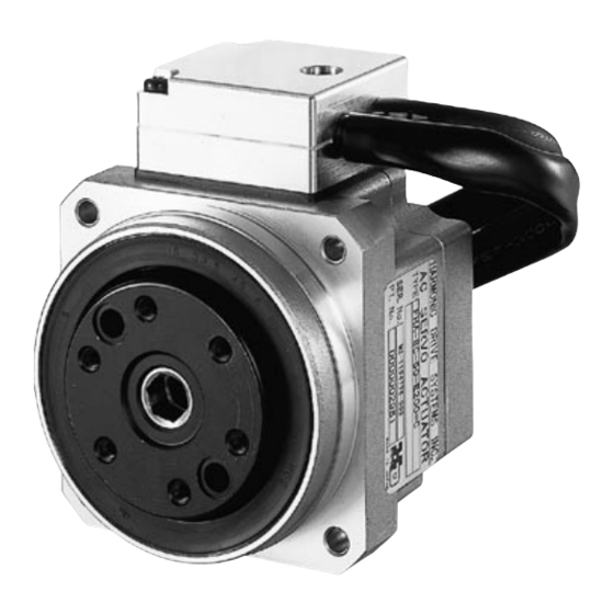
Chapter 1 Overview of the FHA-C mini series FHA-C mini series servo actuators provide high torque and highly accurate rotary motion. The actuator is composed of a Harmonic Drive® component from set (size 8 - 14) for precise motion control and a super-flat AC servomotor. -
Page 5: Ordering Code
Chapter 1 Overview of the FHA-C mini series 1-2 Ordering Code FHA-C mini... - Page 6 Chapter 1 Overview of the FHA-C mini series 1-3 Compatible Servo Drives HA-800 & HA-680 are available for MECHATROLINK-II & CC-Link FHA-C mini...
- Page 7 Chapter 1 Overview of the FHA-C mini series 1-4 Specifications of FHA-C mini actuators 1-4-1 Supply voltage 100V/200VAC Specifications of FHA-C mini series actuators are as follows: Model FHA-8C FHA-11C FHA-14C Item N・m Max. torque Note 2 kgf・m 0.18 0.34 0.49 0.46 0.85...
-
Page 8: Supply Voltage 24Vdc
Chapter 1 Overview of the FHA-C mini series 1-4-2 Supply voltage 24VDC Note 1: The table shows typical output values of actuators. Note 2: Values when using HA-680 drive. Note 3: All values are typical. Note 4: Incremental encoder resolutions are obtained by [motor encoder resolution] x 4 x [reduction ratio]. Motor ABS encoder resolutions are obtained by [motor encoder resolution] x [reduction ratio]. - Page 9 Chapter 1 Overview of the FHA-C mini series 1-5 External dimensions of FHA-C mini actuators The external drawings are shown as follows: 1-5-1 Actuators with side-exiting cables-standard (Incremental encoder) Unit: mm (third angle projection) ■FHA-8C-xxx-US200 ■FHA-11C-xxx-US200 FHA-C mini...
- Page 10 Chapter 1 Overview of the FHA-C mini series ■FHA-14C-xxx-US200 ■Cables - Common (except size 14, 24VDC version *AWG20-4 for FHA-14C-xxx-US200-E) 1-5-2 Actuators with rear exiting cables-option K (Incremental encoder) Unit: mm (third angle projection) ■FHA-8C-xxx-US200-□ □ K ■FHA-11C-xxx-US200-□ □ K FHA-C mini...
- Page 11 Chapter 1 Overview of the FHA-C mini series ■FHA-14C-xxx-US200-□ □ K ■Cables - Common (except size 14, 24VDC version *AWG20-4 for FHA-14C-xxx-US200-E) 1-5-3 Actuators with Absolute Encoder ■FHA-8C-xxx-12S17b □-C Unit: mm (third angle projection) FHA-C mini...
- Page 12 Chapter 1 Overview of the FHA-C mini series Unit: mm (third angle projection) ■FHA-11C-xxx-12S17b □-C Unit: mm (third angle projection) ■FHA-14C-xxx-12S17b □-C ■Cables – Common (except size 14, 24VDC version *AWG20-4 for FHA-14C-xxx-12S17b-E) FHA-C mini...
- Page 13 Chapter 1 Overview of the FHA-C mini series 1-6 Mechanical accuracy of FHA-C mini actuators The machining accuracy of the output flange and the mounting flange are indicated in the table below. Machined accuracy of the output flange unit: mm Machined parts FHA-8C FHA-11C FHA-14C ◎...
-
Page 14: Encoder Resolution
The motors of FHA-C mini actuators are equipped with an incremental encoder of 2000 resolutions. Because the motor rotation is reduced to 30:1 or 50:1 or 100:1 by the Harmonic Drive® component, the resolution of the output flange is 30 or 50 or 100 times the encoder revolution. Additionally, the incremental encoder signal is used in quadrature. - Page 15 Chapter 1 Overview of the FHA-C mini series 1-9 Torsional Stiffness of actuators 1-9-1 Moment stiffness Obliquity The moment stiffness refers to the torsional stiffness when a moment load is applied to the output flange of the actuator (shown in the figure to the right). For example, when a load is applied to the end of an arm attached on the output flange, the face of the output flange tilts in proportion to the moment load.
- Page 16 Chapter 1 Overview of the FHA-C mini series 1-9-2 Torsional stiffness When a torque is applied to the output flange of the actuator with the motor locked, the resulting torsional wind up is near proportional to the torque. The upper right figure shows the torsional stiffness characteristics of the output flange applying torque starting from zero to plus side [+T ] and minus side [–T...
-
Page 17: Impact Resistance
Chapter 1 Overview of the FHA-C mini series 1-10 Rotary direction Forward rotary direction is defined as clockwise (CW) rotation viewing the output flange of the actuator when a driver signals forward commands. The direction can be reversed by the setting of [parameter mode] FWD:CW rotation →[8: rotary direction] of the driver. - Page 18 Chapter 1 Overview of the FHA-C mini series FHA-C mini...
- Page 19 Chapter 1 Overview of the FHA-C mini series 1-14 Operating Range FHA-8C FHA-C mini...
- Page 20 Chapter 1 Overview of the FHA-C mini series FHA-11C FHA-C mini...
- Page 21 Chapter 1 Overview of the FHA-C mini series FHA-14C FHA-C mini...
-
Page 22: Cable Specifications
Chapter 1 Overview of the FHA-C mini series 1-15 Cable specifications The following tables show specifications of the cable for the motor and the encoder of the FHA-C mini actuators. 1-15-1 Incremental Encoder ◆ Motor cable Color Motor lead Motor phase-U White Motor phase-V Black... -
Page 23: Absolute Encoder
Chapter 1 Overview of the FHA-C mini series 1-15-2 Absolute Encoder ◆ Motor cable Pin No. Color Motor lead Motor phase-U White Motor phase-V Black Motor phase-W Green/yellow Connector model: 350715-1 Pin model: 3506901 (E: 770210-1) Manufactured by AMP Connector pin layout ◆... -
Page 24: Chapter 2 Guidelines For Sizing
0.54 2-2 Variable load inertia FHA-C mini series actuators include Harmonic Drive® gearing that has a high reduction ratio. Because of this there are minimal effects of variable load inertias to the servo drive system. In comparison to direct servo systems this benefit will drive the load with a better servo response. - Page 25 Chapter 2 Guidelines for sizing 2-3 Verifying loads The FHA-C mini actuators include a precise cross roller bearing for directly supporting the load weight. For optimal performance, verify that the maximum load weight is less than the allowable load and life and static safety coefficient of the cross roller bearing.
- Page 26 Chapter 2 Guidelines for sizing Calculating average loads: • average radial and axial loads, average output speed When the radial and/or axial loads vary during motion, calculate and verify the life of the cross roller bearing converting the loads to their average values. •...
- Page 27 Chapter 2 Guidelines for sizing • Equivalent dynamic radial load The equivalent dynamic radial load is: Where, the variables of the formula are: Frav: Average radial load in N(kgf); obtained by formula (2). Faav: Average axial load in N(kgf); obtained by formula (3). Circular pitch of roller: See Fig.1 and Table 1.
- Page 28 Chapter 2 Guidelines for sizing • Equivalent static radial load Equivalent static radial is obtained by formula (9) below. Where, the variables of the formula are: Equivalent static radial load in N (kgf); Mmax: Maximum torsional moment in N•m(kgf•m); obtained by the formula (1) Frmax: Maximum radial load in N(kgf);...
-
Page 29: Duty Cycles
Chapter 2 Guidelines for sizing 2-4 Duty cycles When a duty cycle includes many frequent start and stop operations, the actuator generates heat by high starting and braking current. Therefore, it is necessary to study the duty cycle profile. The study is as follows: Screw pitch (mm) 2-4-1 Actuator speed Speed (r/min) -
Page 30: Acceleration Time And Deceleration Time
Chapter 2 Guidelines for sizing • Horizontal linear motion The following formula calculates the torque for horizontal linear motion of mass [W] fed by the screw of pitch [P]. torque (N•m) : coefficient of friction Mass: W W: mass (kg) Pitch: P screw pitch (m) ... - Page 31 Chapter 2 Guidelines for sizing 2-4-5 Calculating equivalent duty Speed The load conditions, which is torque, speed, moment of inertia, acceleration/deceleration time, loading time, are limited by the actuator to drive the load. To select the proper actuator, the equivalent duty of the load should be calculated.
- Page 32 Chapter 2 Guidelines for sizing • Graphs of duty factor ◼ FHA-8C-30 ◼ FHA-11C-30 Radiation plate: 150 x 150 x 6(mm) Radiation plate: 150 x 150 x 6(mm) Operable range Operable range 100 V 100 V 200 V 200 V 24 V 24 V 0.67...
- Page 33 Chapter 2 Guidelines for sizing " " " FHA-mini...
- Page 34 Chapter 2 Guidelines for sizing 2-4-6 Effective torque and average speed Effective torque and the average speed should also be reviewed. (1) The effective torque should be less than allowable continuous torque specified by the driver. (2) The average speed should be less than allowable continuous speed of the actuator. Calculate the effective torque and the average speed of an operating cycle as shown in the former figure.
- Page 35 Chapter 2 Guidelines for sizing 2-4-7 Permissible overloaded time The overloaded time is limited by the protective function in the driver even if the duty cycle is allowed. The limits are shown in the figure below. Input Voltage 100VAC/200VAC FHA-8C-30 FHA-14C-30 FHA-8C-50 FHA-8C-100...
-
Page 36: Chapter 3 Installing The Fha-C Mini Actuator
Chapter 3 Installing the FHA-C mini actuator Chapter 3 Installing the FHA-C mini actuator 3-1 Receiving Inspection Check the following when products are received. •Inspection procedure Check the shipping container and item for any damage that may have been caused during transportation. - Page 37 Chapter 3 Installing the FHA-C mini actuator 3-2 Notice on handling Handle FHA-C mini series actuators with care, specifically: Do not plug the actuators directly into a commercial line power source. This could burn out the actuator, potentially resulting in a fire and/or electrical hazard. WARNING (1) Do not apply impact or unnecessary excessive force to output flange of actuators.
-
Page 38: Installation
Chapter 3 Installing the FHA-C mini actuator 3-3-2 Installation Since the FHA-C mini series actuator is a high precision servomechanism, great care is required for proper installation. When installing the actuator, pay attention to the precision of the assembly. Do not hit the actuator with a hammer. - Page 39 Sleeve Do not disassemble and re-assemble the actuator. Harmonic Drive LLC does not guarantee the actuator has been reassembled by others than the authorized persons by the Harmonic Drive LLC. CAUTION FHA-C mini...
-
Page 40: Extension Cables
Chapter 3 Installing the FHA-C mini actuator 3-4 Extension Cables Three kinds of optional extension cables, 3m/5m/10m length, are available. Ordering model For Motor: EWC – MBxx – A06 – SP For Absolute encoder: EWD – Sxx – A08 – SP For Incremental encoder: xx ----- Cable length: L EWA-Exx-HR16-SP... - Page 41 Appendix 1 Incremental encoder Appendix 1 Incremental Encoder Detailed Specifications Signal Waveform Fig. 1 A, B and Z signal and relationship with U-N motor EMF waveform with CW rotation facing the output flange end a,b,c,d = 0.25T ± 0.15T Tz = T ± 0.5T (The Z phase includes a HIGH state in case of both of A and B phase is H IGH state.)
- Page 42 Appendix 1 Incremental encoder Output Circuit and Example for Receiving Signal Fig. 3 Output circuit of encoder and connection example FHA-mini...
-
Page 43: Appendix 2 Unit Conversion
Appendix 2 Unit conversion Appendix 2 Unit conversion This manual employs SI system for units. Conversion factors between the SI system and other systems are as follows: (1) Length SI system Unit Factor 0.3048 0.0254 Unit Factor 3.281 39.37 SI system (2) Linear speed SI system Unit... - Page 44 Appendix 2 Unit conversion (6) Angle SI system Unit Degree Minute Second Factor 0.01755 2.93x10 4.88x10 Unit Degree Minute Second Factor 57.3 3.44x10 2.06x10 SI system (7) Angular speed SI system rad/s Unit deg/s deg/min r/min Factor 0.01755 2.93x10 6.28 0.1047 Unit deg/s...
-
Page 45: Appendix 3 Moment Of Inertia
Appendix 3 Moment of inertia Appendix 3 Moment of inertia 3-1 Calculation of mass and moment of inertia (1) Both centerlines of rotation and gravity are the same: The following table includes formulas to calculate mass and moment of inertia. m: mass (kg);... - Page 46 Appendix 3 Moment of inertia Object form Mass, inertia, gravity center Object form Mass, inertia, gravity center Rhombus pillar Hexagonal pillar B√3 Isosceles triangle Right triangle pillar pillar ◆ Example of specific gravity The following tables show references of specific gravity. Confirm the specific gravity for the material of the drive load.
- Page 47 Appendix 3 Moment of inertia 3-2 Inertia of cylinder The moment of inertia of a Moment of inertia (kg・m Length(mm) cylinder may be obtained from 1000 Inertia (specific gravity: 2.7) 1000 the graphs to the right. Radius Length FHA-14C-100 FHA-11C-100 FHA-14C-50 FHA-8C-100 The above graph is applied for...
- Page 48 SAFETY GUIDE For actuators, motors, control units and drivers manufactured by Harmonic Drive LLC Read this manual thoroughly before designing the application, installation, maintenance or inspection of the actuator. Indicates potentially hazardous Indicates a potentially hazardous situation, which, if situation, which, if not avoided, could not avoided, may result in minor or moderate personal result in death or serious personal injury.
-
Page 49: Warranty Terms
All efforts have been made to assure that the information in this catalog is complete and accurate. However, Harmonic Drive LLC is not liable for any errors, omissions or inaccuracies in the reported data. Harmonic Drive LLC reserves the right to change the product specifications, for any reason, without prior notice. - Page 50 137 N. Oak Park Ave., Suite 410 6-25-3 Minami-Ohi, Shinagawa-ku Oak Park, IL 60301 Tokyo 141-0013, Japan Harmonic Drive AG T: 800.921.3332 Hoenbergstrasse, 14, D-6555 T: 978.532.1800 Limburg/Lahn Germany F: 978.532.9406 www.HarmonicDrive.net Rev 20191120 Harmonic Drive is a registered trademark of Harmonic Drive LLC.