Harmonic Drive RSF supermini Series Manual
Ac servo actuator
Hide thumbs
Also See for RSF supermini Series:

Subscribe to Our Youtube Channel
Related Manuals for Harmonic Drive RSF supermini Series


Summary of Contents for Harmonic Drive RSF supermini Series
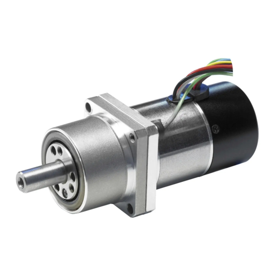
- Page 1 AC Servo Actuator RSF supermini Series Manual (With RSF-3C and RSF-5B) ISO14001 ISO9001...
- Page 2 Introduction Thank you very much for your purchasing our RSF supermini series servo actuator. Be sure to use sufficient safety measures when installing and operating the equipment so as to prevent an accident resulting in a serious physical injury damaged by a malfunction or improper operation.
-
Page 3: Safety Guide
SAFETY GUIDE To use the servo system safely, be sure to read SAFETY GUIDE and other parts of this document carefully and fully understand the information provided herein before using the driver. NOTATION Important safety information you must note is provided herein. Be sure to observe these instructions. Indicates a potentially hazardous situation, which, if not avoided, could result in death or serious personal injury. -
Page 4: Safety Note
SAFETY GUIDE SAFETY NOTE Precautions when using a direct drive motor NOTICES ON DESIGN BE SURE TO READ THE MANUAL FOR DESIGNING. Always use under followings conditions: The motor is designed to be used for indoor. Ambient temperature: 0°C to 40°C Ambient humidity: 20% to 80%RH (Non-condensation) CAUTION Vibration: 49 m/s... - Page 5 SAFETY GUIDE Precautions when using a driver NOTICES ON DESIGN BE SURE TO READ THE MANUAL FOR DESIGNING. Always use drivers under followings conditions: The driver generates heat. Take extra caution for radiation and use it under the following conditions. Mount in a vertical position keeping sufficient distance.
- Page 6 SAFETY GUIDE OPERATIONAL PRECAUTIONS BE SURE TO READ THE MANUAL BEFORE OPERATING THE PRODUCT. Never change wiring while power is active. Make sure to turn OFF the power before detaching wires, or disconnecting or connecting the connectors. Failure to observe this caution may result in electric shock or uncontrollable operation.
-
Page 7: Table Of Contents
NOTATION ....................1 LIMITATION OF APPLICATIONS ..............1 SAFETY NOTE ..................... 2 Contents ......................... 5 Chapter 1 Overview of the RSF supermini Series Overview of RSF supermini Series ............1-1 Major characteristics ................. 1-1 Ordering information ................. 1-2 Actuator Model ..................1-2 1-4 Combinations with drivers ................ -
Page 8: Contents
Contents Examining duty ..................2-4 Examining effective torque and average rotational speed ......2-8 Permissible overloaded time ..............2-9 Chapter 3 Installing the actuator Receiving inspection ................. 3-1 Notice on handling ..................3-2 Location and installation ................3-3 Environment of location ................3-3 Considerations into External Noise ............ - Page 10 Chapter 1 Overview of the RSF supermini Series Overview of RSF supermini Series ········································ 1-1 Major characteristics ·························································· 1-1 Ordering information ·························································· 1-2 Combinations with drivers···················································· 1-2 Specifications of RSF supermini actuators ······························ 1-4 External dimensions of actuators ·········································· 1-6 One-way positioning accuracy ··············································...
-
Page 11: Overview Of Rsf Supermini Series
Actuators with an electromagnetic brake are also included in the lineup. They can meet fail-safe requirements of equipment to prevent accidents upon power supply failure. The RSF supermini series can contribute to downsizing of driving of robot joints, semiconductor/LCD panel manufacturing equipment, machine tools, and other FA equipment. By utilizing its small and high-torque characteristics, it can also be used for small equipment and for research. -
Page 12: Ordering Information
Special specification No symbol: Standard product SP: Special product Combinations with drives The The RSF supermini series actuators can be used in combination with the DCJ, DDP, and HA-680 drives. • Drives can perform position control, speed control, and torque control. - Page 13 1-4 Combinations with drives...
-
Page 14: Specifications Of Rsf Supermini Actuators
1-5 Specifications of RSF supermini actuators Specifications of RSF supermini actuators Specifications of actuators are as follows: Time rating: Continuous Service temperature: 0~40°C Excitation method: Permanent magnet type Storage temperature: -20~+60°C Humidity Insulation class: 20~80%RH (no condensation) (Operating/Storage) Withstanding Vibration AC500V/min 49m/s (10-400Hz) - Page 15 1-5 Specifications of RSF supermini actuators Size RSF-3C RSF-5B Item Encoder pulses Pulse/ (motor shaft) Encoder resolution (Output shaft: Pulse/ 24,000 40,000 80,000 60,000 100,000 200,000 when multiplied Rotation by 4) Note 4 Input power DC24±10% supply Motor voltage shaft 0.18 0.29 0.44...
-
Page 16: External Dimensions Of Actuators
1-6 External dimensions of actuators External dimensions of actuators The external drawings are shown as follows: RSF-3C-XXX-E020-C 2-plane cut Line locating Motor lead wire range of Encoder cable wire Motor lead wire (Finished outside diameter: φ5Max) Encoder lead wire (Finished outside diameter: φ3.3Max) Clamp filter(2) ZCAT1518-0730(TDK) Note) For detailed external dimensions, check the delivery specification drawing issued by us. - Page 17 1-6 External dimensions of actuators RSF-5B-XXX-E050-C 3-M2x3 evenly spaced 2-φ2.3 evenly spaced FG line Motor lead wire (Finished outside diameter: φ6Max) Encoder lead wire (Finished outside diameter: φ3.3Max) Clamp filter(2) ZCAT1518-0730(TDK) RSF-5B-XXX-E050-BC(with brake) 3-M2x3 evenly spaced 2-φ2.3 evenly spaced FG line Motor lead wire Motor and Brake lead wire (Finished outside diameter:...
-
Page 18: One-Way Positioning Accuracy
The RSF supermini series contains a HarmonicDrive® speed reducer for precision control and positioning errors of the motor shaft are therefore compressed to 30:1, 50:1 or 100:1 by speed reduction. -
Page 19: Torsional Stiffness
1-8 Torsional stiffness Torsional stiffness When a torque is applied to the output flange of the actuator with the motor locked, the resulting torsional wind up is near proportional to the torque. The upper right figure shows the torsional stiffness characteristics of the output flange applying torque starting from zero to plus side [+T ] and minus side [–T... -
Page 20: Detector Resolution
An encoder with 200 pulses for RSF-3C, 500 pulses for RSF-5B per rotation is incorporated in the motor unit of the RSF supermini series actuators, and the motor output is decelerated by 30:1, 50:1, or 100:1 by the Harmonic Drive® speed reducer. Therefore, the resolution per one rotation of the actuator output shaft is 30, 50, or 100 times of the actual encoder resolution. -
Page 21: Mechanical Accuracy
1-10 Mechanical accuracy 1-10 Mechanical accuracy The machining accuracy of the output flange and the mounting flange of RSF supermini actuators are indicated in the table below. RSF-3C RSF-5B Machined accuracy of the output flange * T.I.R. unit: mm Symbol Accuracy value Machined parts Model... -
Page 22: Allowable Load
Allowable load Allowable radial load and allowable thrust load The gear head used in the RSF supermini series incorporates the high-precision 4-point contact ball bearing for direct support of external load (output part). The allowable radial load and thrust load of the output shaft are shown below. -
Page 23: Radial Load When The Operating Point Is Different
1-11 Allowable load Radial load when the operating point is different If the operating point of radial load is different, the allowable radial load value is also different. The relation between radial load position L and allowable radial value F is obtained from the following formula. -
Page 24: Rotary Direction
1-12 Rotary direction The rotary direction of the RSF supermini series actuators when a forward rotation command is given from the HA-680 driver is forward rotation seen from the output shaft side (i.e. clockwise: CW). The rotary direction of the HA-680 can be switched by using the Parameter → “20: Rotary direction command”... - Page 25 1-15 Operating range The following graphs show the operating ranges of the RSF supermini series actuators. (1) Continuous Motion Range The range allows continuous operation for the actuator. (2) 50% Duty Motion Range This range indicates the torque rotation speed which is operating in the 50% duty operation (the ratio of operating time and delay time is 50:50).
- Page 26 1-15 Operating range RSF-5B-30-US050-C, RSF-5B-30-US050-BC Radiation plate 150×150×3 (mm) Acc./dec. range 50% duty range Continuous range Speed [rpm] RSF-5B-50-US050-C, RSF-5B-50-US050-BC Radiation plate 150×150×3 (mm) Acc./dec. range Continuous range 50% duty range Speed [rpm] RSF-5B-100-US050-C, RSF-5B-100-US050-BC Radiation plate 150×150×3 (mm) Acc./dec. range Continuous range 50% duty range Speed [rpm]...
-
Page 27: Cable Specifications
1-16 Cable specifications 1-16 Cable specifications The following tables show specifications of motor lead wires, brake lead wires and encoder lead wires of the RSF supermini actuators. Motor cable Pin No. Color Signal name Remark (RED) Motor phase-U White (WHT) Motor phase-V Black (BLK) - Page 28 1-16 Cable specifications 1-18...
- Page 30 Chapter 2 Selection of the RSF supermini Series This chapter explains how to select a proper RSF supermini series actuator. Allowable load moment of inertia ··········································· 2-1 Variable load inertia···························································· 2-1 Verifying loads ·································································· 2-1 Examining operating status ·················································· 2-2...
-
Page 31: Allowable Load Moment Of Inertia
In the case of the RSF supermini series, this is an extremely large number, such as R = 30, R = 50 or R = 100, that is R2 = 900, R2 = 2500, or R2 = 10000. The ratio is Js' JS≒1. This means that drive systems are hardly affected by the load moment of inertia variation. -
Page 32: Calculating Load Torque
Linear speed (mm/min) Load moment of inertia Calculate the load moment of inertia driven by the RSF supermini series actuator. For the calculation methods, refer to [Appendix 1 Conversion of unit] (Page A-1). Tentatively select an RSF supermini actuator referring to section [2-1 Allowable load moment of inertia] (P2-1) with the calculated value. -
Page 33: Acceleration Time And Deceleration Time
2-4 Duty Cycles Horizontal linear motion The following formula calculates the torque for horizontal linear motion of mass [W] fed by the screw of pitch [P]. × µ × × × π Mass: W Pitch: P torque (N・m) μ: Friction: μ... - Page 34 • Try to reduce the load moment of inertia. • Re-examine the gear ratio and gear head model. Calculating equivalent duty During the selecting process of the RSF supermini series, Speed ts: stop time the temporal variability of torque and rotation speed need to be taken into account.
- Page 35 2-4 Duty Cycles How to obtain K and K and example of duty calculation 2 As a result of Calculation Example 1 shown below, the selected actuator RSF-5B-50 works fine, so RSF-5B-50 can be used for duty factor graphs. Operation conditions: •...
- Page 36 2-4 Duty Cycles Graphs of duty factor RSF-3C-30-E020-C Radiation plate: 85×85×3[mm] 0.15 Acc./dec. range 0.12 0.09 0.06 0.67 0.03 KL=0.33 0.00 Speed [rpm] 回転速度[r/min] RSF-3C-50-E020-C Radiation plate: 85×85×3[mm] 0.25 Acc./dec. range 0.20 0.15 0.10 0.67 0.05 KL=0.33 0.00 回転速度[r/min] Speed [rpm] ...
- Page 37 2-4 Duty Cycles RSF-5B-30-E050-C RSF-5B-30-E050-BC Radiation plate: 150×150×3[mm] Radiation plate: 150×150×3[mm] Acc./dec. range Acc./dec. range 0.67 0.67 KL=0.33 KL=0.33 Speed [rpm] 回転速度[r/min] Speed [rpm] 回転速度[r/min] RSF-5B-50-E050-BC RSF-5B-50-E050-C Radiation plate: 150×150×3[mm] Radiation plate: 150×150×3[mm] Acc./dec. range Acc./dec. range 0.67 0.67 KL=0.33...
-
Page 38: Examining Effective Torque And Average Rotational Speed
2-4 Duty Cycles Examining effective torque and average rotational speed Addionally to the former studies, the effective torque and the average speed should be studied. (1) The effective torque should be less than allowable continuous torque specified by the driver. (2) The average speed should be less than allowable continuous speed of the actuator. -
Page 39: Permissible Overloaded Time
Permissible overloaded time In case RSF supermini series is intermittently operated in allowable continuous torque or more, the overloaded time is limited by the protective function in the driver even if the duty cycle is allowed. The limits are shown in the figure below. -
Page 40: Chapter 3 Installing The Actuator
Chapter 3 Installing the actuator The following explains the installation procedures of the actuators. Receiving inspection ·························································· 3-1 Notice on handling ····························································· 3-2 Location and installation ······················································ 3-3... -
Page 41: Receiving Inspection
If the item is damaged, immediately report the damage to the dealer it was purchased from. (2) A label is attached on the side of the RSF supermini series actuator. Confirm the products you ordered by comparing with the model on the [TYPE] line of the label. If it is different, immediately contact the dealer it was purchased from. -
Page 42: Notice On Handling
3-2 Notice on handling Notice on handling Handle the RSF supermini series actuator carefully by observing the notices specified below. Do not plug the actuators directly into a commercial line power source. This could burn out the actuator, potentially resulting in a fire WARNING and/or electrical hazard. -
Page 43: Location And Installation
3-3 Location and installation Location and installation Environment of location The environmental conditions of the installation location for RSF supermini series actuators must be as follows. Determine an appropriate installation location by observing these conditions without fail. Service temperature:0°C to 40°C The temperature in the cabinet may be higher than the atmosphere depending on the power loss of housed devices and size of the cabinet. -
Page 44: Installation
3-3 Location and installation Installation Since the RSF supermini series actuator is a high precision servo mechanism, great care is required for proper installation. Install the actuator taking care not to damage accurately machined surfaces. Do not hit the actuator with a hammer. - Page 45 3-3 Location and installation...
-
Page 46: Chapter 4 Motor Shaft Retention Brake(Rsf-5B)
Chapter 4 Motor shaft retention brake(RSF-5B) RSF-5B actuator is standard-equipped with a motor shaft holding brake. (Option symbol: B) An external brake is not required to meet the fail safe and other requirements. The brake has 2 coils; one for releasing brake, and another for retaining the released state. -
Page 47: Motor Shaft Retention Brake Specifications
4-1 Motor shaft retention brake specifications Motor shaft retention brake specifications Gear ratio Item Single disc dry type deenergisation operation type Method (Separate attraction coil and retention coil) Brake operating voltage 24VDC±10% Current consumption during release (at 20°C) Current consumption during 0.05 retention of release (at 20°C) N・m... -
Page 48: Controlling The Brake Power Supply
4-2 Controlling the brake power supply Controlling the brake power supply Using an extension cable (Recommended method) The optional extension cables for brakes (EWA-B××-JST03-TMC) incorporate a circuit that controls the brake current. You don’t have to control the brake current, so it is recommended to use the actuator with a brake in combination with a relay cable for brakes. - Page 49 4-2 Controlling the brake power supply The power supply to the brake must be controlled. Control the power supply to the brake as described in [4-2 Controlling the brake power supply] (P4-2). If the current flows continuously to the attraction coil, the actuator burns due to temperature rise, causing fire or electric shock.
-
Page 50: Chapter 5 Options
Chapter 5 Options Options you can purchase as necessary are explained in this chapter. Extension cables ······························································· 5-1 Extension cable wire bound specifications······························· 5-2 Connectors ······································································ 5-5... - Page 51 5-1 Extension cables Extension cables There are extension cables that connect the RSF supermini series actuator and driver. There are 3 types of extension cables for encoders, motors, and brakes. Select an appropriate type according to the model of the actuator you ordered.
- Page 52 5-2 Extension cable wire bound specifications ● Extension cable DCJ/DDP Driver (1) For encoders EWA-E××-JST09-SP Cable length (03=3m, 05=5m, 10=10m) (2) For motors EWA-M××-JST04-SP Cable length (03=3m, 05=5m, 10=10m) (3) For brakes EWA-B××-JST03-TMC Cable length (03=3m, 05=5m, 10=10m) Application of 24VDC (non polar) Mfg by J.S.T.
-
Page 53: Relay Cables
5-2 Extension cable wire bound specifications Extension cable wire bound specifications The following tables show the wire bound specifications of the relay cables. (1) For encoders (EWA-E××-JST09-3M14) Actuator side Driver side Signal Signal Signal Signal Pin NO. Pin NO. Pin NO. Pin NO. - Page 54 5-2 Extension cable wire bound specifications (3) For brakes (EWA-B××-JST03-TMC) Actuator side Power supply side for brake Pin NO. Wire color Wire color Connector Round crimp-style Red, black terminal 1.25-4 (nonpolar) White With insulating coating Black Connector Retainer: PMS-03V-S Housing: PARP-03V Contact: S(B)PA-001T-P0.5 J.S.T.
-
Page 55: Connectors
5-3 Connectors Connectors HA-680 Driver There are 2 types of connectors for the driver for different set types: Connector model: CNK-HA68-S1 For CN1, CN2, actuator line connection, power supply connection…..4 types Connector model: CNK-HA68-S2 For CN2, power supply connection……………………………………….2 types Connector for CN2 Connector for CN1 Mfg by Sumitomo 3M... - Page 56 5-3 Connectors...
-
Page 58: Appendix
Chapter 6 Appendix This chapter explains the conversion of unit and the moment of inertia. Conversion of unit ······························································ A-1 Moment of inertia ······························································· A-3... -
Page 59: Conversion Of Unit
A-1 Conversion of unit Conversion of unit This technical manual basically uses the SI unit system. The conversion coefficients between the SI unit system and other unit systems are shown below. (1) Length SI unit Unit Coefficient 0.3048 0.0254 Unit Coefficient 3.281 39.37... -
Page 60: Moment Of Inertia
A-1 Conversion of unit (6) Angle SI unit Unit Deg. Min. Sec. Coefficient 0.01755 2.93x10 4.88x10 Unit Deg. Min. Sec. Coefficient 57.3 3.44x10 2.06x10 SI unit (7) Angular speed SI unit rad/s Unit Deg./s Deg./min r/min Coefficient 0.01755 2.93x10 6.28 0.1047 Unit Deg./s... -
Page 61: Calculation Formulas For Mass And Moment Of Inertia
A-2 Moment of inertia Moment of inertia 1. Calculation formulas for mass and moment of inertia (1) When center of revolution and line of center of gravity match Calculation formulas for mass and moment of inertia are shown below. m:Mass (kg), Ix, Iy, Iz: moment of inertia (kgm ) making Axes x, y and z as centers of revolution G:Distance from edge surface of center of gravity (m) ρ:Density (kg/m... - Page 62 A-2 Moment of inertia Mass, inertia, position of Mass, inertia, position of Shape of object Shape of object center of gravity center of gravity Rhombic prism Regular hexagon prism ρ ρ B√3 Ix = ...
-
Page 63: Moment Of Inertia Of Circular Cylinder
A-2 Moment of inertia 2. Moment of inertia of circular cylinder Approximate values of moment of Length (mm) Moment of inertia (kgm 1000 inertia of circular cylinder can be Moment of inertia (Density 2700) 1000 calculated from the graph on the right. - Page 64 (2) disassembling, modification or repair by others than Harmonic Drive Systems, Inc. (3) imperfection caused by the other than the RSF supermini series actuator and the HA-680 servo driver. (4) disaster or others that does not belong to the responsibility of Harmonic Drive Systems, Inc.
- Page 65 137 N. Oak Park Ave. Suite 410, Oak Park, IL 60301 California Office 333 W. San Carlos St. Suite 1070, San Jose, CA 95110 HarmonicDrive.net | 978-532-1800 ® "HarmonicDrive " is a registered trademark of Harmonic Drive Systems, Inc. 202009-11R-HDLL...
Need help?
Do you have a question about the RSF supermini Series and is the answer not in the manual?
Questions and answers