Harmonic Drive RSF supermini Series Manual
Ac servo actuator
Hide thumbs
Also See for RSF supermini Series:

Related Manuals for Harmonic Drive RSF supermini Series


Summary of Contents for Harmonic Drive RSF supermini Series
- Page 1 AC Servo Actuator RSF supermini Series + Mitsubishi Electric AC servo amplifier "MELSERVO-J4" SSCNETⅢ/H communication compatible Manual (With RSF-3C and RSF-5B) ISO14001 ISO9001...
- Page 2 Introduction Introduction Thank you very much for your purchasing our RSF supermini series servo actuator. Be sure to use sufficient safety measures when installing and operating the equipment so as to prevent an accident resulting in a serious physical injury damaged by a malfunction or improper operation.
-
Page 3: Safety Guide
SAFETY GUIDE SAFETY GUIDE To use the servo system safely, be sure to read SAFETY GUIDE and other parts of this document carefully and fully understand the information provided herein before using the driver. NOTATION Important safety information you must note is provided herein. Be sure to observe these instructions. Indicates a potentially hazardous situation, which, if not avoided, could result in death or serious personal injury. -
Page 4: Safety Note
SAFETY GUIDE SAFETY NOTE ITEMS YOU SHOULD NOTE WHEN USING THE ACTUATOR NOTICES ON DESIGN BE SURE TO READ THE MANUAL FOR DESIGNING. Always use under followings conditions: The motor is designed to be used for indoor. Ambient temperature: 0°C to 40°C Ambient humidity: 20% to 80%RH (Non-condensation) CAUTION Vibration: 49 m/s... - Page 5 SAFETY GUIDE OPERATIONAL PRECAUTIONS BE SURE TO READ THE MANUAL BEFORE OPERATING THE PRODUCT. Do not make a voltage resistance test. Do not perform a megger test or voltage resistance test. Failure to observe this caution may result in damage to the control circuit of the driver. Please consult our sales office, if you intent to make a voltage resistance CAUTION test.
- Page 6 SAFETY GUIDE ITEMS YOU SHOULD NOTE WHEN USING THE SERVO AMPLIFIER Read the "MR-J4-_B Servo Amp Technical Manuals" (No.SH (name) 030101) and ensure safe operation. Before using this product, be sure to read the "MELSERVO-J4 SERIES AC SERVO SAFETY GUIDE" which comes together with the servo amplifier. ...
-
Page 7: Table Of Contents
LIMITATION OF APPLICATIONS ..............1 SAFETY NOTE ..................... 2 Contents ......................5 Chapter 1 Overview of the RSF supermini Series 1-1 Overview of RSF supermini Series ............... 1-1 1-2 Major characteristics..................1-1 1-3 Ordering information ..................1-2 Actuator Model ..................1-2 1-4 Actuator - Amplifier Combinations .............. -
Page 8: Contents
Contents Examining duty ..................2-4 Examining effective torque and average rotational speed ......2-8 Permissible overloaded time ..............2-9 Chapter 3 Installing the actuator 3-1 Receiving inspection..................3-1 3-2 Notice on handling ..................3-1 3-3 Location and installation ................3-2 Environment of location ................ - Page 9 Overview of the RSF supermini Series Outlines of servo actuator models, specifications, external dimensions, etc., are explained in this chapter. Overview of RSF supermini Series ········································ 1-1 Major characteristics ·························································· 1-1 Ordering information ·························································· 1-2 Actuator - Amplifier Combinations ········································· 1-2 Specifications of RSF supermini actuators·······························...
-
Page 10: Overview Of Rsf Supermini Series
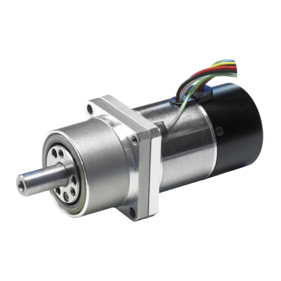
1-1 Overview of RSF supermini Series Overview of RSF supermini Series The RSF supermini series are ultra-compact AC servo actuators that combine a speed reducer ® HarmonicDrive for ultra-precision control with a ultra-compact AC servo motor developed to maximize the performance of a speed reducer. -
Page 11: Ordering Information
1-3 Ordering information Ordering information Model codes for the RSF supermini series actuators are as follows: Actuator Model RSF-5 B-50-E 050-C-SP Model: AC servo actuator Series: RSF series Frame size: 3 or 5 Design version ® Reduction ratio of HarmonicDrive... -
Page 12: Specifications Of Rsf Supermini Actuators
1-5 Specifications of RSF supermini actuators Specifications of RSF supermini actuators Specifications of actuators are as follows: Time rating: Continuous Structure: Totally enclosed self cooling type Excitation method: Permanent magnet type Lubricant: Grease (Harmonic Grease) RSF-3C RSF-5B Item Model 0.13 0.21 0.30 Maximum torque... -
Page 13: External Dimensions Of Actuators
1-6 External dimensions of actuators External dimensions of actuators The external drawings are shown as follows: RSF-3C-XXX-E020-CJ 2-plane cut Line locating Motor lead wire range of Encoder cable wire Motor lead wire (Finished outside diameter: φ5Max) Encoder lead wire (Finished outside diameter: φ3.3Max) Clamp filter(2) ZCAT1518-0730(TDK) Note) For detailed external dimensions, check the delivery specification drawing issued by us. - Page 14 1-6 External dimensions of actuators RSF-5B-XXX-E050-CJ 3-M2x3 evenly spaced 2-φ2.3 evenly spaced FG line Motor lead wire (Finished outside diameter: φ6Max) Encoder lead wire (Finished outside diameter: φ3.3Max) Clamp filter(2) ZCAT1518-0730(TDK) RSF-5B-XXX-E050-BCJ(with brake) 3-M2x3 evenly spaced 2-φ2.3 evenly spaced FG line Motor lead wire Motor and Brake lead wire (Finished outside diameter:...
-
Page 15: One-Way Positioning Accuracy
The following table shows the “one-way positioning accuracy." The following table contains representing values. ® RSF supermini series actuators house the speed reducer HarmonicDrive for precision control, positioning errors of the motor shaft are compressed by reduction ratio to 30, 50 or 100. Actually, the angle transmission error of the speed reducer determines the positional accuracy. -
Page 16: Torsional Stiffness
1-8 Torsional stiffness Torsional stiffness When a torque is applied to the output flange of the actuator with the motor locked, the resulting torsional wind up is near proportional to the torque. The upper right figure shows the torsional stiffness characteristics of the output flange applying torque starting Torsional angle from zero to plus side [+T... -
Page 17: Actuator Resolution
1-9 Actuator resolution Actuator resolution RSF supermini series actuators are equipped with a 200-pulse (Model No. 3) or a 500-pulse (Model No. 5) encoder, and the speed is reduced to 1/30, 1/50 or 1/100 using the speed reducer ® HarmonicDrive for precision control. -
Page 18: Mechanical Accuracy
1-10 Mechanical accuracy 1-10 Mechanical accuracy The mechanical accuracies of the output shaft and mounting flange for RSF supermini series actuators are shown below: RSF-3C RSF-5B Mechanical accuracy * T.I.R. unit: mm Symbol Accuracy value Subject Dimension Model RSF-3C RSF-5B Runout of the tip of the output shaft 0.03... -
Page 19: Allowable Load
Allowable load Allowable radial load and allowable thrust load The gear head used in the RSF supermini series incorporates the high-precision 4-point contact ball bearing for direct support of external load (output part). The allowable radial load and thrust load of the output shaft are shown below. -
Page 20: Radial Load When The Operating Point Is Different
1-11 Allowable load Radial load when the operating point is different If the operating point of radial load is different, the allowable radial load value is also different. The relation between radial load position L and allowable radial value F is obtained from the following formula. -
Page 21: Rotary Direction
Rotary direction The rotation direction of the actuator is defined as a clockwise (CW) rotation as viewed from the output shaft when a FWD rotation command is given to a RSF supermini series actuator from a Mitsubishi Electric J4 amplifier. -
Page 22: Operable Range
1-15 Operable range 1-15 Operable range The following graphs show the usable ranges of the RSF supermini series actuators. Acceleration and deceleration range: This range indicates the torque rotation speed at which the product can be operated at this instant. - Page 23 1-15 Operable range RSF-5B-30-E050-CJ RSF-5B-50-E050-CJ RSF-5B-30-E050-BCJ RSF-5B-50-E050-BCJ Radiation plate: 150×150×3 (mm) Radiation plate: 150×150×3 (mm) Acc./dec. range Acc./dec. range 50% duty rang 50% duty rang Continuous range Continuous range Speed [r/min] Speed [r/min] RSF-5B-100-E050-CJ RSF-5B-100-E050-BCJ Radiation plate: 150×150×3 (mm) Acc./dec. range 50% duty rang Continuous range Speed [r/min]...
-
Page 24: Cable Specifications
1-16 Cable specifications 1-16 Cable specifications The following tables show specifications of motor lead wires, brake lead wires and encoder lead wires of the RSF supermini actuators. Motor lead wire Pin No. Color Signal name Remark (RED) Motor phase-U White (WHT) Motor phase-V Black... - Page 25 Chapter 2 Selection of the RSF supermini Series This chapter explains how to select a proper RSF supermini series actuator. Allowable load moment of inertia ··········································· 2-1 Variable load inertia···························································· 2-1 Verifying loads ·································································· 2-1 Examining operating status ·················································· 2-2...
-
Page 26: Allowable Load Moment Of Inertia
In the case of the RSF supermini series, this is an extremely large number, such as R = 30, R = 50 or R = 100, that is R = 900, R = 2500, or R = 10000. -
Page 27: Examining Operating Status
Linear speed (mm/min) Calculating and examining load inertia moment Calculate the load moment of inertia driven by the RSF supermini series actuator. For the calculation methods, refer to [Appendix 1 Conversion of unit] (Page A-1). Tentatively select an RSF supermini actuator referring to section [2-1 Allowable load moment of inertia] (P2-1) with the calculated value. -
Page 28: Acceleration Time And Deceleration Time
2-4 Examining operating status Horizontal linear motion The following formula calculates the torque for horizontal linear motion of mass [W] fed by the screw of pitch [P]. × µ × × × π Mass: W Pitch: P torque (N・m) μ: coefficient of friction Friction: μ... -
Page 29: Examining Duty
• Try to reduce the load moment of inertia. • Review the reduction ratio and actuator model number. Examining duty During the selecting process of the RSF supermini series, ts: stop time Speed the temporal variability of torque and rotation speed need to be taken into account. - Page 30 2-4 Examining operating status Example: 2 How to obtain K and K and example of duty calculation As a result of Calculation Example 1 shown below, the selected actuator RSF-5B-50 works fine, so RSF-5B-50 can be used for duty factor graphs. Operation conditions: •...
- Page 31 2-4 Examining operating status Graphs of duty factor RSF-3C-30-E020-CJ Radiation plate: 85×85×3[mm] Acc./dec. range KL=0.33 Speed [r/min] RSF-3C-50-E020-CJ Radiation plate: 85×85×3[mm] 加減速運転領域 Acc./dec. range KL=0.33 KL=0.33 Speed [r/min] RSF-3C-100-E020-CJ Radiation plate: 85×85×3[mm] Acc./dec. range 0.67 KI=0.33 KL=0.3 Speed [r/min]...
- Page 32 2-4 Examining operating status RSF-5B-30-E050-BCJ RSF-5B-30-E050-CJ Radiation plate: 150×150×3[mm] Radiation plate: 150×150×3[mm] 放 熱 板 : 150x150x3[mm] Acc./dec. range Acc./dec. range 0.67 0.67 KL=0.33 KL=0.33 Speed [r/min] Speed [r/min] RSF-5B-50-E050-CJ RSF-5B-50-E050-BCJ Radiation plate: 150×150×3[mm] Radiation plate: 150×150×3[mm] Acc./dec.
-
Page 33: Examining Effective Torque And Average Rotational Speed
2-4 Examining operating status Examining effective torque and average rotational speed Addionally to the former studies, the effective torque and the average speed should be studied. (1) The effective torque should be less than allowable continuous torque specified by the driver. (2) The average speed should be less than allowable continuous speed of the actuator. -
Page 34: Permissible Overloaded Time
Permissible overloaded time When a RSF supermini series actuator is intermittently operated in allowable continuous torque or more, the time the torque can be output continuously is limited by the overload detection function of the servo amplifier even within the allowable duty range. This overload detection time is shown in the figure below. - Page 35 Chapter 3 Installing the actuator The following explains the installation procedures of the actuators. Receiving inspection ·························································· 3-1 Notice on handling ····························································· 3-1 Location and installation ······················································ 3-2 Initial settings for amplifier ··················································· 3-4 Excitation of actuators ························································ 3-5 MR-Configurator 2 operation to set PL13 ··········································· 3-6...
-
Page 36: Receiving Inspection
If the item is damaged, immediately report the damage to the dealer it was purchased from. (2) A label is attached on the side of the RSF supermini series actuator. Confirm the products you ordered by comparing with the model on the [TYPE] line of the label. If it is different, immediately contact the dealer it was purchased from. -
Page 37: Location And Installation
3-3 Location and installation Location and installation Environment of location The environmental conditions of the installation location for RSF supermini series actuators must be as follows. Determine an appropriate installation location by observing these conditions without fail. Service temperature:0°C to 40°C The temperature in the cabinet may be higher than the atmosphere depending on the power loss of housed devices and size of the cabinet. -
Page 38: Installation
3-3 Location and installation Installation Since the RSF supermini series actuator is a high precision servo mechanism, great care is required for proper installation. Install the actuator taking care not to damage accurately machined surfaces. Do not hit the actuator with a hammer. -
Page 39: Initial Settings For Amplifier
3-4 Initial settings for amplifier Initial settings for amplifier In order to control your actuator with a J4 amplifier, the following parameters must be set. Actuator Setting value Parameter RSF-3C RSF-5B PA01 Operation mode 1060 PA17 Servo motor series setting (*1) PA18 Servo motor type setting... -
Page 40: Excitation Of Actuators
3-5 Excitation of actuators Excitation of actuators The "MR-J4W2-0303B6-MX940J" servo amplifier, which is compatible with this actuator, detects the magnetic pole at the first excitation after the power is turned on. At that time, the actuator output shaft rotates about ±0.5 degree max. Precautions for using this method are described below. -
Page 41: Mr-Configurator 2 Operation To Set Pl13
3-6 MR-Configurator 2 operation to set PL13 MR-Configurator 2 operation to set PL13 Follow the following procedure to set PL13: Resolution multiplying factor. (1) Connect the servo amplifier to a PC with a USB cable and start MR Configurator 2. (2) Select [Update Parameter Setting Range…]. - Page 42 3-6 MR-Configurator 2 operation to set PL13...
-
Page 43: Chapter 4 Motor Shaft Retention Brake(Rsf-5B)
Chapter 4 Motor shaft retention brake(RSF-5B) RSF-5B actuator is standard-equipped with a motor shaft holding brake. (Option symbol: B) An external brake is not required to meet the fail safe and other requirements. The brake has 2 coils; one for releasing brake, and another for retaining the released state. -
Page 44: Motor Shaft Retention Brake Specifications
4-1 Motor shaft retention brake specifications Motor shaft retention brake specifications Gear ratio Item Single disc dry type deenergisation operation type Method (Separate attraction coil and retention coil) Brake operating voltage 24VDC±10% Current consumption during release (at 20°C) Current consumption during 0.05 retention of release (at 20°C) N・m... -
Page 45: Controlling The Brake Power Supply
4-2 Controlling the brake power supply Controlling the brake power supply Using a relay cable (Recommended method) The optional relay cables for brakes (EWA-B××-JST03-TMC) incorporate a circuit that controls the brake current. You don’t have to control the brake current, so it is recommended to use the actuator with a brake in combination with a relay cable for brakes. - Page 46 4-2 Controlling the brake power supply The power supply to the brake must be controlled. Control the power supply to the brake as described in [4-2 Controlling the brake power supply] (P4-2). If the current flows continuously to the attraction coil, the actuator burns due to temperature rise, causing fire or electric shock.
-
Page 47: Chapter 5 Options
Chapter 5 Options Options you can purchase as necessary are explained in this chapter. Relay cables ····································································· 5-1... -
Page 48: Relay Cables
5-1 Relay cables Relay cables A relay cable is used to connect an RSF supermini series actuator with an amplifier. There are 3 types of relay cables for encoders, motors, and brakes. Select an appropriate type according to the model of the actuator you ordered. - Page 49 5-1 Relay cables (2) For motors EWA-M××-JST04-NC-M Cable length (03=3m, 05=5m, 10=10m) : L Pin No. Signal name U phase V phase W phase 【Shield line/PE line connections for connector installation】 When installing the connector supplied with the MR-J4W2-0303B6-MX940J amplifier, connect the shield line and PE line as follows: When the actuator connected to the MR-J4W2-0303B6-MX940J amplifier has 1 shaft ◆...
- Page 50 5-1 Relay cables (3) For brakes (RSF-5B only) EWA-B××-JST03-TMC Cable length (03=3m, 05=5m, 10=10m) Round crimp-style Mfg by J.S.T. Mfg. Co., Ltd. Application of 24VDC (non polar) terminal PARP-03V 1.25-4 Pin No. Signal name White Black...
-
Page 51: Appendix
Chapter 6 Appendix This chapter explains the conversion of unit and the moment of inertia. Conversion of unit ······························································ A-1 Moment of inertia ······························································· A-3... -
Page 52: Conversion Of Unit
A-1 Conversion of unit Conversion of unit This technical manual basically uses the SI unit system. The conversion coefficients between the SI unit system and other unit systems are shown below. (1) Length SI unit Unit Coefficient 0.3048 0.0254 Unit Coefficient SI unit 3.281... -
Page 53: Moment Of Inertia
A-1 Conversion of unit (6) Angle SI unit Unit Deg. Min. Sec. Coefficient 0.01755 2.93x10 4.88x10 Unit Deg. Min. Sec. Coefficient 57.3 3.44x10 2.06x10 SI unit (7) Angular speed SI unit rad/s Unit Deg./s Deg./min r/min Coefficient 0.01755 2.93x10 6.28 0.1047 Unit Deg./s... -
Page 54: Calculation Formulas For Mass And Moment Of Inertia
A-2 Moment of inertia Moment of inertia 1. Calculation formulas for mass and moment of inertia (1) When center of revolution and line of center of gravity match Calculation formulas for mass and moment of inertia are shown below. m:Mass (kg), Ix, Iy, Iz: moment of inertia (kgm ) making Axes x, y and z as centers of revolution G:Distance from edge surface of center of gravity (m) ρ:Density (kg/m... - Page 55 A-2 Moment of inertia Mass, inertia, position of Mass, inertia, position of Shape of object Shape of object center of gravity center of gravity Rhombic prism Regular hexagon prism ρ ρ B√3 Ix = ...
-
Page 56: Moment Of Inertia Of Circular Cylinder
A-2 Moment of inertia 2. Moment of inertia of circular cylinder Approximate values of moment of Moment of inertia (kgm Length (mm) 1000 inertia of circular cylinder can be Moment of inertia (Density 2700) 1000 calculated from the graph on the right. - Page 57 (2) disassembling, modification or repair by others than Harmonic Drive Systems, Inc. (3) imperfection caused by the other than the RSF supermini series actuator and the HA-680 servo driver. (4) disaster or others that does not belong to the responsibility of Harmonic Drive Systems, Inc.
- Page 58 42 Dunham Ridge, Beverly, Massachusetts 01915 U.S.A. L.L.C.: TEL: +1-978-532-1800 FAX: +1-978-532-9406 ® "HarmonicDrive " is a trademark of Harmonic Drive Systems, Inc. No. 2107-1R-TRSFmM-E ® The academic or general nomenclature of our products "HarmonicDrive " is "strain wave gearing."...
Need help?
Do you have a question about the RSF supermini Series and is the answer not in the manual?
Questions and answers