
Related Manuals for VersaLogic EPM-4


Summary of Contents for VersaLogic EPM-4
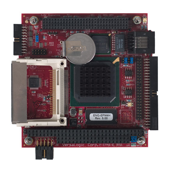
- Page 1 Reference Manual DOC. REV. 3/16/2009 EPM-4 (Lynx) AMD ÉlanSC520 processor module with 10/100 Ethernet, and PC/104-Plus interface.
- Page 2 EPM-4 AMD ÉlanSC520 processor module with 10/100 Ethernet, and PC/104-Plus interface MEPM4...
- Page 3 BIOS information and upgrades • Utility routines and benchmark software Note: This is a private page for EPM-4 users only. It cannot be reached through our web site. You must ctly to find the support page. enter this address dire...
- Page 4 All Rights Reserved Notice: Although every effort has been made to ensure this document is error-free, VersaLogic makes no representations or warranties with respect to this product and specifically disclaims any implied warranties of merchantability or fitness for any particular purpose.
-
Page 6: Table Of Contents
Table of Contents Introduction ........................1 Description.......................... 1 Technical Specifications ..................... 2 EPM-4 Block Diagram ....................... 3 RoHS-Compliant Version....................4 About RoHS......................4 RoHS Compliant Cables ..................4 Technical Support ....................... 5 Repair Service......................5 Configuration / Operation....................7 Overview..........................7 Electrostatic Discharge .................. - Page 7 Table of Contents Connector Location Diagram................20 Connector Functions and Interface Cables ............21 Jumper Block Locations ....................22 Jumper Summary ....................23 Power Supply........................24 Power Connectors ....................24 Power Requirements .................... 25 Lithium Battery....................25 CPU........................... 26 System RAM........................26 Memory........................
- Page 8 Table of Contents Appendix B — References ................... 45...
-
Page 9: Introduction
Keyboard, mouse, AT motherboard peripherals The EPM-4 is a complete computer system in one board. It may be used alone or with expansion modules. It features a PC/104-Plus expansion interface for fast PCI-based interface to a wide variety of PC/104 and PC/104-Plus stacking modules. This card is designed to be used primarily as an Ethernet node processor card. -
Page 10: Technical Specifications
Embedded-PCI (PC/104-Plus) – Full compliance, 3.3V or 5V modules RoHS: EPM-4g, h – Full compliance Weight: EPM-4c, g – 0.117 kg (0.275 lbs) EPM-4e, h – 0.116 kg (0.255 lbs) Specifications are subject to change without notice. Introduction – 2 EPM-4 Reference Manual... -
Page 11: Epm-4 Block Diagram
EPM-4 Block Diagram EPM-4 Block Diagram EPM-4 Reference Manual Introduction – 3... -
Page 12: Rohs-Compliant Version
HS C OMPLIANT ABLES Adapter cables for the EPM-4 are available in RoHS compliant and RoHS noncompliant versions. Compliance or noncompliance is indicated by the part number prefix. “CBR” indicates RoHS compliance. “CBL” indicates RoHS noncompliance. For applications that require RoHS compliance, use only the RoHS compliant (“CBR”... -
Page 13: Technical Support
Technical Support Technical Support If you have problems that this manual can’t help you solve, first visit the EPM-4 Product Support web page below. If you have further questions, contact VersaLogic for technical support at (541) 485-8575. You can also reach our technical support engineers via e-mail at Support@VersaLogic.com. -
Page 15: Configuration / Operation
ESD protective pouch. The lithium battery may explode if mistreated. Do not recharge, disassemble, or dispose of in fire. Dispose of used batteries promptly. EPM-4 Reference Manual Configuration / Operation – 7... -
Page 16: Initial Configuration And Setup
Initial Configuration and Setup The following list describes the components recommended for setting up a typical development system. ECOMMENDED OMPONENTS • EPM-4 Board and cable kit • ATX Power Supply • EPM-VID-3 for video support • Keyboard with PS/2 connector, mouse •... -
Page 17: Cmos Setup / Boot Procedure
Insert bootable floppy disk into floppy drive. • Reset computer using push button reset. • See VersaLogic KnowledgeBase article VT1476 – EPM-4 CMOS Setup Reference more information about these parameters. Basic CMOS Configuration +------------------------------------------------------------------------------+ System Bios Setup - Basic CMOS Configuration (C) 2002 General Software, Inc. -
Page 18: Console Redirection
To enable console redirection, there must be no video device detected, the console redirection option in Custom Configuration must be set to Auto, and there must be a terminal (such as Windows HyperTerm) detected at COM2. Configuration / Operation – 10 EPM-4 Reference Manual... -
Page 19: Cmos Setup / Ide Configuration
Do not attempt to assign a drive letter to a CD-ROM drive. The drivers required to use these devices will automatically assign a drive letter to the device when loaded. Boot Order This field allows you to specify the order in which the BIOS looks for boot devices. EPM-4 Reference Manual Configuration / Operation – 11... -
Page 20: Cmos Setup / Advanced Configuration
THERNET Default: Disabled When enabled, this will disable the Ethernet media data rate auto-negotiation and force it to 10- BaseT mode. Note: Some drivers will put the Ethernet back into auto-negotiation mode. Configuration / Operation – 12 EPM-4 Reference Manual... -
Page 21: Ps/2 Mouse (Irq12)
IMINGS Default: Normal The GP (ISA) bus timings may need to be slowed to accommodate ISA Plug-n-Play cards. This option modifies registers in the GP Bus Controller, MMCR offsets C08h through C10h. EPM-4 Reference Manual Configuration / Operation – 13... -
Page 22: Com1 (03F8H) Rs-232
These options allow manual IRQ routing of PCI devices. PCI devices can share an interrupt. In most cases, the cost of doing this is slightly decreased Note: system performance and slightly increased interrupt response time. Configuration / Operation – 14 EPM-4 Reference Manual... -
Page 23: Using Custom Cmos Defaults
BIOS setup screen to undo any mistakes. For example, it would be a mistake to disable a COM port that is required for console redirection when there is no video device available. EPM-4 Reference Manual Configuration / Operation – 15... -
Page 25: Reference
Reference Physical Dimensions The EPM-4 complies with all PC/104-Plus standards. Dimensions are given below to help with pre-production planning and layout. 3.575 3.370 3.070 2.330 0.400 3.300 0.000 -0.200 Figure 1. Dimensions (Not to scale. All dimensions in inches.) EPM-4 Reference Manual... -
Page 26: Height Dimensions
Physical Dimensions EIGHT IMENSIONS 0.51 0.44 0.06 0.42 0.44 Figure 2. Height Dimensions (Not to scale. All dimensions in inches.) Reference – 18 EPM-4 Reference Manual... -
Page 27: Hardware Assembly
PC/104 (ISA) modules must NOT be positioned between the Lynx and any PC/104-Plus (PCI) modules on the stack. The PC/104 pass-through connector on the EPM-4 Rev 4 is keyed (pins B10 and C19 missing) to provide greater compatibility with other PC/104 compliant devices. -
Page 28: External Connectors
IAGRAM Figure 4. Connector Locations On the EPM-4 Rev 4 and above, the pass-through PC/104 (ISA) connector is keyed (pins B10 and C19 missing) for greater compatibility with PC/104 devices, as shown in the figure below. Pin Side of ISA Connector... -
Page 29: Connector Functions And Interface Cables
Note: VersaLogic adapter cables for the EPM-4 are available in RoHS compliant and RoHS noncompliant versions. Compliance or noncompliance is indicated by the part number prefix. “CBR” indicates RoHS compliance. “CBL” indicates RoHS noncompliance. -
Page 30: Jumper Block Locations
Jumper Block Locations Note: The diagram below shows the as-shipped configuration for jumpers on Rev. 4.xx and earlier boards. On Rev. 5.xx and later boards, no jumper is installed on V3. Figure 6. Jumper Block Locations Reference – 22 EPM-4 Reference Manual... -
Page 31: Jumper Summary
— Run Time System BIOS occupies E0000h to FFFFFh — Master System BIOS occupies E0000h to FFFFFh Note: The Run Time System BIOS is field upgradeable using the BIOS upgrade utility. See www.VersaLogic.com/private/lynxsupport.asp for further information. V4[3-4] — General Purpose Input Bit —... -
Page 32: Power Supply
Some manufacturers include a pin-1 indicator on the crimp housing that corresponds to pin-10 of the J8 power connector. Some manufacturers include a pin-1 indicator here that corresponds to pin-10 of the power connector pinout CBL/CBR-1008 Figure 7. J8 and CBL/CBR-1008 Pin Numbering Reference – 24 EPM-4 Reference Manual... -
Page 33: Power Requirements
OWER EQUIREMENTS The EPM-4 only requires +5 volts (±5%) for proper operation. The voltage required for the RS- 232 ports is generated with an on-board DC/DC converter. A variable low-voltage supply circuit provides power to the CPU and other on-board devices. -
Page 34: Cpu
Real Time Clock The EPM-4 features a year 2000 compliant, battery-backed 146818 compatible real time clock/calendar chip. Under normal battery conditions, the clock will maintain accurate timekeeping functions during periods when the board is powered off. -
Page 35: Battery Backed Static Ram
Battery Backed Static RAM Battery Backed Static RAM The EPM-4 can be ordered with an optional 2 MB of Battery Backed Static RAM (BBSRAM). This BBSRAM is powered by the boards RTC battery when main power is turned off. Jumper V1, which is used to clear CMOS RAM, does not affect the BBSRAM. -
Page 36: Ide Hard Drive / Compactflash / Cd-Rom Interface
CompactFlash (CF) media. Use CMOS Setup to specify the drive parameters of the attached drives. An activity indication LED is provided on the EPM-4. The yellow LED of D5 (See page 22) will show that activity is detected on the IDE interface. -
Page 37: Utility Connector (J7)
2 and 1 (Ground) of J2. (3) Pin 2 of D1 (CBL/CBR-5009) is connected to +5V (Protected), which provides power to the IDE LED. Pin 4 of D1 is connected to Ground. EPM-4 Reference Manual Reference – 29... -
Page 38: Keyboard/Mouse Interface
The 5V supply for this feature is protected by a self resetting fuse. This 1 Amp fuse is used to protect KB, mouse, speaker, and LED. UTTON ESET A normally open, momentary action push-button reset switch can be connected between J7[37] and J7[38]. Shorting J7[37] to ground will cause the EPM-4 to reboot. ENERAL URPOSE IMER NPUTS Two flexible general-purpose timer inputs can be used for timing and counting applications. -
Page 39: Parallel / Floppy Port
ARALLEL PERATION The EPM-4 includes a standard bi-directional/EPP/ECP compatible LPT port which resides at the PC standard address of 378h. The port can be enabled or disabled and interrupt assignments can be made via the CMOS setup screen. The LPT mode is also set via the CMOS setup screen. -
Page 40: Ethernet Interface
Ethernet Interface Ethernet Interface The EPM-4 features an industry-standard 10baseT / 100baseTX Ethernet interface based on the Intel 82551ER Ethernet controller. This PCI based interface chip is widely supported. Drivers are readily available to support a variety of operating systems such as QNX, VxWorks and other RTOS vendors. -
Page 41: Watchdog Timer
; These are 16-bit memory writes. End program loop For detailed programming instructions for the integrated watchdog timer, see chapter 19 of the ÉlanSC520 Microcontroller User's Manual, and chapter 16 of the Register Set Manual. EPM-4 Reference Manual Reference – 33... -
Page 42: Expansion Bus
Expansion Bus Expansion Bus The EPM-4 will accept up to eight expansion modules, up to four of which can be PC/104-Plus (PCI) expansion modules. The EPM-4 uses 3.3V PCI signaling but is 5V tolerant. PC/104-P (PCI B PC/104-Plus modules can be secured directly to the top or bottom of the EPM-4. Make sure to correctly configure the "slot position"... - Page 43 PC/104 I/O modules should be addressed in the 104h – 3FFh address range. Care must be taken to avoid the I/O addresses shown in the On-Board I/O Devices table on page 37. These ports are used by on-board peripherals and video devices. EPM-4 Reference Manual Reference – 35...
-
Page 44: Memory And I/O Map
Configuration Base Address Register (CBAR), located at I/O address FFFCh. Refer to the ÉlanSC520 Register Set Manual for further details. EMORY The lower 1 MB memory map of the EPM-4 is arranged as shown in the following table. Table 8: Memory Map Start... -
Page 45: I/O Map
Memory and I/O Map I/O M The following table lists the common I/O devices in the EPM-4 I/O map. User I/O devices should be added in the 104h – 3FFh range, using care to avoid the devices already in the map as shown below. -
Page 46: Interrupt Configuration
Available on PC/104 (ISA) bus Default IRQ assignments: Timer 0 Keyboard Slave PIC cascade COM2 COM1 Unused Floppy drive Unused Real-Time Clock Unused Unused PCI Interrupt A,B,C,D PS/2 Mouse Math Co-processor IDE controller Unused Reference – 38 EPM-4 Reference Manual... -
Page 47: Special Control Register
Reserved — These bits have no function. General Purpose Input — Indicates the status of TTL input GPI = 0 Jumper V4 [3-4] = Out GPI = 1 Jumper V4 [3-4] = In Note: This bit is a read-only bit. EPM-4 Reference Manual Reference – 39... -
Page 48: Revision Indicator Register
Revision Indicator Register Revision Indicator Register REVIND (READ ONLY) 00E1h REV1 REV0 This register is used to indicate the revision level of the EPM-4 product. Mnemonic Description D7-D3 PC4-PC0 Product Code — These bits are hard coded to represent the product type. The EPM-4 will always read as 11011. -
Page 49: Map And Paging Control Register
Page Select — Selects which 64K block of FLASH will be mapped into the page frame. Memory Range within FLASH 000000h to 00FFFFh 010000h to 01FFFFh 020000h to 02FFFFh 030000h to 03FFFFh 040000h to 04FFFFh 050000h to 05FFFFh 060000h to 06FFFFh 070000h to 07FFFFh EPM-4 Reference Manual Reference – 41... -
Page 51: Appendix A - Cbl/Cbr-5009
Conta-Clip 10250.4 5 pin screw terminal COM3 Conta-Clip 10250.4 5 pin screw terminal Resistor DigiKey P332CCT-ND 332 ohms Reset Button E-Switch 800SP9B7M6RE Right angle momentary switch Speaker Challenge Electronics DBX05 Miniature speaker EPM-4 Reference Manual Appendix A — CBL/CBR-5009 – 43... - Page 52 PLED# TX3+ SPKO# TX3- JTB251-01-05 TRX3+ TRX3- TX4+ TX4- JTB251-01-05 MKPWR TRX4+ TRX4- TMRIN0 TMRIN1 JTB251-01-05 PBRST# SPKO# SPEAKER DUAL PS/2 MKPWR MTH3 MTH4 MTH1 MTH2 MKPWR Figure 11. CBL/CBR-5009 Schematic Appendix A — CBL/CBR-5009 – 44 EPM-4 Reference Manual...
- Page 53 Consortium, (www.pc104.org) PC/104 Resource Guide PC/104-Plus Specification PC/104 Consortium, (www.pc104.org) PC/104 Resource Guide General PC Documentation Microsoft Press (www.microsoft.com/learning/books) The Programmer’s PC Sourcebook General PC Documentation Powell's Books (www.powells.com) The Undocumented PC EPM-4 Reference Manual Appendix B — References – 45...
Need help?
Do you have a question about the EPM-4 and is the answer not in the manual?
Questions and answers