Table of Contents
Advertisement
Quick Links
Advertisement
Table of Contents

Subscribe to Our Youtube Channel
Related Manuals for VersaLogic Bengal VL-EPMe-30


Summary of Contents for VersaLogic Bengal VL-EPMe-30
- Page 1 Hardware Reference Manual DOC. REV. 01 MAR 2016 Bengal (VL-EPMe-30) Intel Atom™-based Single Board ® Computer with Dual Ethernet, Video, USB, SATA, Serial I/O, Digital I/O, Trusted Platform Module security, Counter/Timers, Mini PCIe, mSATA, SPX, and PCIe/104™ OneBank™ Interface...
- Page 2 Copyright © 2016 VersaLogic Corp. All rights reserved. Notice: Although every effort has been made to ensure this document is error-free, VersaLogic makes no representations or warranties with respect to this product and specifically disclaims any implied warranties of merchantability or fitness for any particular purpose.
-
Page 3: Customer Support
Customer Support If you are unable to solve a problem after reading this manual, visiting the product support page, or searching the KnowledgeBase, contact VersaLogic Technical Support at (503) 747-2261. VersaLogic support engineers are also available via e-mail at Support@VersaLogic.com. -
Page 4: Operating Systems
Use an active DP-to-HDMI adapter Use a passive DP-to-HDMI adapter and request a custom BIOS from VersaLogic. Legacy USB support is not available in xHCI (USB 3.0) mode. Non-UEFI pre-OS and installation environments may require EHCI (USB 2.0) mode for USB keyboard functionality. -
Page 5: Table Of Contents
Contents Introduction ........................1 Description .......................... 1 Features and Construction ..................1 Technical Specifications ..................... 3 Thermal Considerations ...................... 3 Block Diagram ........................4 Cautions ..........................5 Electrostatic Discharge ..................5 Handling Care ......................5 Earth Ground Requirement ..................5 Battery Usage ...................... - Page 6 PCIe Mini Card LEDs ..................38 Digital I/O ......................... 38 DIO Guidelines ....................39 SPX Expansion Bus ......................40 VersaLogic SPX Expansion Modules ..............41 SPI Registers ......................42 Thermal Considerations ..................... 45 Selecting the Correct Thermal Solution for Your Application ........45 Heat Plate ......................
- Page 7 Contents EPMe-30 Thermal Characterization ................. 49 Test Results......................50 Installing the VersaLogic Thermal Solutions ..............53 Installing the Passive Heat Sink ................53 Installing the Heat Sink Fan ................54 Appendix A – References.................... 55 Figures Figure 1. Major Components and Connectors (Top Side) ................2 Figure 2.
- Page 8 Contents Table 14: Supported Power States ......................... 29 Table 15: VGA Video Output Pinout ......................31 Table 16: mini DisplayPort Connector Pinout ....................32 Table 17: Ethernet Connector Pinout (J1, J7) ....................33 Table 18: Ethernet Status LEDs ........................34 Table 19: SATA Port Pinout .........................
-
Page 9: Introduction
Introduction Description Features and Construction The Bengal is a feature-packed single board computer (SBC) designed to support OEM applications where high reliability and long-term availability are required. Its features include: † † Intel Atom “Bay Trail” processor, Trusted Platform Module quad, dual, or single core with ... -
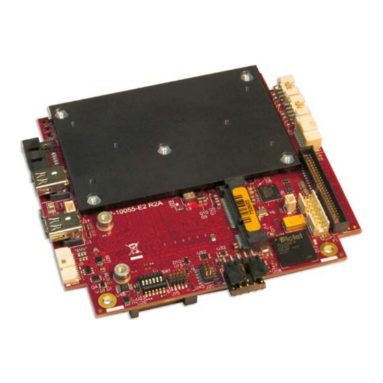
Page 10: Figure 1. Major Components And Connectors (Top Side)
Introduction Item Description Item Description Intel Atom “Bay Trail” SoC External battery connector PMIC power regulator PCIe Minicard (mSATA) connector FPGA Power connector PCI Express Switch Reserved Ethernet 1 PHY Reserved Ethernet 0 PHY Configuration switches Ethernet port 0 VGA connector Ethernet port 1 Mini DisplayPort1 Digital I/O... -
Page 11: Technical Specifications
Introduction Item Description Item Description PCI connector SPI Flash device (backup) Trusted Platform Module (TPM) DDR3 SO-DIMM socket USB 3.0 connector COM port transceiver PCIe/104 OneBank connector COM port jumper block SPI Flash device (primary) Ethernet transformers Figure 2. Major Components and Connectors (Bottom Side) Technical Specifications See the Bengal Data Sheet... -
Page 12: Block Diagram
Introduction Block Diagram Figure 3. Bengal Board Block Diagram Bengal (VL-EPMe-30) Reference Manual... -
Page 13: Cautions
Introduction Cautions Electrostatic Discharge CAUTION: Electrostatic discharge (ESD) can damage circuit boards, disk drives, and other components. The circuit board must only be handled at an ESD workstation. If an approved station is not available, some measure of protection can be provided by wearing a grounded antistatic wrist strap. -
Page 14: Configuration And Setup
Inspect the system visually for any damage that may have occurred in shipping. Contact Support@VersaLogic.com immediately if any items are damaged or missing. Gather all the peripheral devices you plan to attach to the Bengal and their interface and power cables. -
Page 15: Bios Setup Utility
The standard PC architecture used on the VL-EPMe-30 makes the installation and use of most of the standard x86-based operating systems very simple. The operating systems listed on the VersaLogic OS Compatibility Chart use the standard installation procedures provided by the maker of the OS. -
Page 16: Physical Layout
Physical Layout Dimensions and Mounting Bengal Dimensions The Bengal complies with PC/104-Plus dimensional standards. Figure 4 shows the board’s dimensions to help with pre-production planning and layout. Figure 4. Bengal Dimensions and Mounting Holes (Not to scale. All dimensions in inches.) Bengal (VL-EPMe-30) Reference Manual... -
Page 17: Vl-Cbr-5015 Dimensions
Physical Layout VL-CBR-5015 Dimensions Figure 5 shows the dimensions and mounting holes for the VL-CBR-5015. All dimensions are in inches Illustration is not to scale 5.50 5.10 1.17 1.57 1.95 1.24 0.065 BENGAL_05 Figure 5. VL-CBR-5015 Dimensions and Mounting Holes Hardware Assembly The Bengal provides both PCI and PCIe/104 OneBank connectors for adding expansion modules to the bottom of the stack. -
Page 18: External Connectors
Physical Layout External Connectors Bengal Connector Locations – Top Side Item Description Item Description Des. Des. Ethernet Port 0 Reserved Ethernet Port 1 Reserved Digital I/O VGA Connector User I/O Mini DisplayPort1 SPX Connector CPU Fan External Battery Connector Mini DisplayPort2 PCIe Minicard (mSATA) SATA Connector Power Connector... -
Page 19: Bengal Connector Locations - Bottom Side
Physical Layout Bengal Connector Locations – Bottom Side Item Description Des. USB 3.0 PCIe/104 OneBank DDR3 SO-DIMM Figure 7. Connector Locations (Bottom) Bengal (VL-EPMe-30) Reference Manual... -
Page 20: Bengal Connector Functions And Interface Cables
Physical Layout Bengal Connector Functions and Interface Cables Table 1 provides information about the function, mating connectors, and transition cables for Bengal connectors. Page numbers indicate where additional information is available. Table 1: Connector Functions and Interface Cables Connector Transition Function Mating Connector Cable Description... -
Page 21: Vl-Cbr-5015 Connector Locations
Physical Layout VL-CBR-5015 Connector Locations Battery Paddleboard Auxiliary Speaker Adapter COM1 (Top) Power Reset USB5 USB3 USB1 COM2 (Bottom) (Top) (Top) Programmable USB4 USB2 LED (Top) (Bottom) (Bottom) Power LED (Bottom) BENGAL_08 Figure 8. VL-CBR-5015 Connectors Integrator’s Note: USB ports 1-4 on the VL-CBR-5015 paddleboard (connectors J4 and J5) are all hubbed, so throughput may not be optimal. -
Page 22: Vl-Cbr-5015 Connector Functions
Physical Layout VL-CBR-5015 Connector Functions Table 2: VL-CBR-5015 Functions Reference Function PCB Connector Description Provides power to CMOS RAM and RTC registers when main power is –— Back-up battery off. • FCI 20021511-00050T1LF 1.27 mm, 50-pin • Paddleboard adapter Oupiin 3216-A50G00SBA keyed header •... -
Page 23: Vl-Cbr-2004B Dimensions And Connectors
Physical Layout VL-CBR-2004B Dimensions and Connectors The VL-CBR-2005 digital I/O adapter is comprised of the VL-CBR-2005A cable and the VL-CBR- 2004 I/O paddleboard. The paddleboard provides a screw terminal interface for all digital I/O lines. Figure 9 shows the VL-CBR-2004 board’s dimensions, connectors, and jumper blocks. All dimensions are in inches. -
Page 24: Jumper Blocks
Physical Layout Jumper Blocks Jumper block V1 is located on the bottom side of the board. The board is shipped with two jumpers installed, but only one side of each jumper is placed on a pin of the V1 jumper block. In this configuration, the jumpers do not connect any signals. -
Page 25: Configuration Switches
Physical Layout Configuration Switches Figure 11 shows the as-shipped switch configuration with all switches in the Off position. The Off position is toward the center of the board. Switch Block BENGAL_11 Figure 11. Location of SW1 Configuration Switch Block Table 5: Switch Setting Summary Switch Description Position... -
Page 26: System Features
Note: This input is only necessary for expansion modules plugged into either the PC104 PCI connector (J11) or the PCIe/104 OneBank connector (J10) that require this voltage. Figure 12 shows the VersaLogic standard pin numbering for this type of 10-pin power connector and the corresponding mating connector. Some manufacturers include... -
Page 27: Power Requirements
Power Delivery Considerations Using the VersaLogic approved power supply (VL-PS200-ATX) and power cable (VL-CBR-1008) ensures high quality power delivery to the board. Customers who design their own power delivery methods should take into consideration the guidelines below to ensure good power connections. -
Page 28: System Ram
Voltage 1.35 V Type DDR3L (VersaLogic VL-MM9 Series modules) Resetting BIOS to Factory Defaults Reset the BIOS to default settings using the following the instructions: Power off the Bengal and set SW1 switch position 3 to the On position (toward the outer edge of the board). -
Page 29: Real Time Clock (Rtc)
System Features Real Time Clock (RTC) The Bengal features a real-time clock/calendar (RTC) circuit. The RTC can be set using the BIOS Setup utility. The Bengal supplies RTC voltage in S5, S3, and S0 states, but requires an external +2.75 V to +3.3 V battery connection to maintain RTC functionality and RTC CMOS RAM when the Bengal is not powered. -
Page 30: Table 9: Pci/104-Express
System Features Integrator’s Note: The PCIe/104 OneBank version of the interface does not implement the Bank 2 or Bank 3 connectors. CAUTION: No attempt should be made to add SUMIT-based products to the OneBank connector. The SUMIT interface is not mechanically or electrically compatible with the OneBank interface. Attempting to use SUMIT expansion modules will damage the OneBank connector and void the warranty. -
Page 31: Interfaces And Connectors
Interfaces and Connectors User I/O Connector Table 10 lists the pinout of the 50-pin User I/O connector (J18). Table 10: J18 User I/O Connector Pinout Signal Signal • RXD1 (RS-232) Ground • RXD1– (RS-422/485) • CTS1 (RS-232) Ground • RXD1+ (RS-422/485) •... -
Page 32: Serial Ports
Interfaces and Connectors Table 11 shows signal routing of the J18 User I/O connector to the VL-CBR-5015 paddleboard. Table 11: User I/O Connector Signal Routing to VL-CBR-5015 Paddleboard CBR-5015 CBR-5015 Signal Signal Connector Connector RS-232 RS-422/485 USB1 +5.0 V J5 Top Ground Ground USB1 Data +... -
Page 33: Rs-485 Mode Line Driver Control
Interfaces and Connectors RS-485 Mode Line Driver Control The transmit line driver can be automatically turned on and off based on data availability in the UART output FIFO. This mode can be enabled in the BIOS Setup utility. The transmit line driver can be enabled in the BIOS Setup utility. -
Page 34: Battery Connector
Interfaces and Connectors Battery Connector Connector J8 can be used to connect an external battery to the Bengal board. A compatible battery is available from VersaLogic, part number VL-CBR-0203. Signal Battery Figure 13. Location and Pin Configuration of J8 Battery Connector VL-CBR-0203 External Battery Module The VL-CBR-0203 is an external battery module compatible with the Bengal board. -
Page 35: Ethernet Status Leds
BIOS. By default, EHCI is used. Some older operating systems (such as MS-DOS) may not support xHCI. The VersaLogic VL-CBR-1015 cable is a USB 3.0 Micro-A to Micro-B adapter. The VL-CBR-1015 cable can be used to connect the Bengal to any certified USB 3.0 hubs. -
Page 36: Leds
Interfaces and Connectors LEDs Programmable LED Connector J18 includes an output signal for a programmable LED. Connect the cathode of the LED to J18 pin 38; connect the anode to +5 V. An on-board 332 Ω resistor limits the current to 15 mA. -
Page 37: Power Button
Interfaces and Connectors Power Button Connector J18 includes an input for a power button. Shorting J18 pin 41 to ground causes the board to enter an S5 power state (similar to the Windows Shutdown state). Shorting it again returns the board to the S0 power state and reboots the board. The button can be configured in Windows to enter an S3 power state (Sleep, Standby, or Suspend-to-RAM), an S4 power state (Hibernate or Suspend-to-Disk), or an S5 power state (Shutdown or Soft-Off). -
Page 38: Pushbutton Reset
Interfaces and Connectors Pushbutton Reset Connector J18 includes an input for a pushbutton reset switch. Shorting J18 pin 40 to ground causes the Bengal to reboot. The input can be connected to ground using the normally open contacts of a pushbutton switch or a relay, or with a switching transistor (open-collector or open-drain) capable of sinking 1 mA. -
Page 39: Video Interfaces
Interfaces and Connectors Video Interfaces The Bengal incorporates the Intel Gen-7 graphics core with four Execution Units and Turbo Boost. It supports two independent displays. It also supported formats including DirectX 11, OpenGL 3, VP8, MPEG2, H.264, VC1, 2 HD streams (1080p@30fps), Flash and WMP support. Analog and dual mini DisplayPort video interfaces support Extended Desktop, Clone, and Twin display modes. -
Page 40: Displayport
Interfaces and Connectors DisplayPort Two DisplayPorts are provided using two 20-pin mini DisplayPort connectors at locations J3 and J22. DisplayPort consists of three interfaces: Main Link – transfers high-speed isochronous video and audio data. Auxiliary channel – used for link management and device control; the EDID is read over this interface. -
Page 41: Ethernet
Two Ethernet interfaces are provided at connector locations J7 (Ethernet 0) and J1 (Ethernet 1). The I210-IT Ethernet controller auto-negotiates connection speed. VersaLogic cable VL-CBR- 0804 adapts the 8-pin Ethernet connector to an RJ-45 connector. Table 17 lists the pinout of the J1 and J7 Ethernet connectors. -
Page 42: Ethernet Status Leds
Interfaces and Connectors Ethernet Status LEDs On-board status LEDs are provided at locations D5 (single yellow) and D4 (dual green/yellow) for Ethernet 0, and D2 (single yellow) and D1 (dual green/yellow) for Ethernet 1. Table 18 lists the states of the Ethernet status LEDs. Figure 17 shows the locations of the Ethernet status LEDs. Table 18: Ethernet Status LEDs Port/LED Color... -
Page 43: Sata Port
Interfaces and Connectors SATA Port The Bengal provides one 3 GB/s SATA port (J2). The SATA connector is a standard 7-pin right- angle connector with latching capability. Power to the SATA drive is provided by the ATX power supply. Note that the standard SATA drive power connector is different from the typical 4-pin Molex connector used on IDE drives. -
Page 44: Pcie Mini Card / Msata
An Intel Centrino Advanced-N 6205 Wireless Express Mini Card (VL-MPEe-W2) is available from VersaLogic. A Wi-Fi antenna (VL-CBR- ANT01) and a 12-inch Wi-Fi card to bulkhead RP-SMA transition cable (VL-CBR-0201) are also available. For more information, contact Sales@VersaLogic.com. - Page 45 Interfaces and Connectors PCIe Mini Card PCIe Mini Card mSATA mSATA Signal Name Function Signal Name Function Ground Ground 1.5V 1.5V power +1.5V 1.5V power Ground Ground SMB_CLK SMBus clock Two Wire I/F Two wire I/F clock PETn0 PCIe transmit – Host transmitter diff.
-
Page 46: Pcie Mini Card Leds
After reset, the DIO lines are set as inputs with pull-ups that will be detected as a HIGH state to external equipment. VersaLogic provides a set of application programming interface (API) calls for managing the DIO lines. See the VersaAPI Support Page for information. -
Page 47: Dio Guidelines
Interfaces and Connectors Table 22: J21 I/O Connector Pinout VL-CBR-2004B VL-CBR-2004B J21 Pin Signal Connector Digital I/O 1 Digital I/O 2 Digital I/O 3 Digital I/O 4 Ground Digital I/O 5 Digital I/O 6 Digital I/O 7 Digital I/O 8 Ground Digital I/O 9 (optional Timer Channel 5 Output) Digital I/O 10 (optional Timer Channel 5 Output) -
Page 48: Spx Expansion Bus
Interfaces and Connectors Power States CPU power states will affect voltage rails driving DIO circuits as described below: DIOs and their pull-up resistors will remain powered in all CPU power states (except when power is turned off). Power control during CPU power states on user devices connected to DIO lines is dependent on the application design. -
Page 49: Versalogic Spx Expansion Modules
VersaLogic SPX Expansion Modules VersaLogic offers several SPX modules that provide a variety of standard functions, such as analog input, digital I/O, CANbus controller, and others. These are small boards (1.2 x 3.78 inches) that can mount on the PC/104 stack, using standard standoffs, or up to two feet away from the baseboard. -
Page 50: Spi Registers
Interfaces and Connectors SPI Registers A set of control and data registers are available for SPI transactions. The following tables describe the SPI control registers (SPICONTROL and SPISTATUS) and data registers (SPIDATA3-0). SPICONTROL (READ/WRITE) C88h CPOL CPHA SPILEN1 SPILEN0 MAN_SS Table 24: SPI Control Register 1 Bit Assignments Description Mnemonic... -
Page 51: Table 25: Spi Control Register 2 Bit Assignments
Interfaces and Connectors SPISTATUS (READ/WRITE) C89h IRQSEL1 IRQSEL0 SPICLK1 SPICLK0 HW_IRQ_EN LSBIT_1ST HW_INT BUSY Table 25: SPI Control Register 2 Bit Assignments Mnemonic Description IRQ Select – These bits select which IRQ is asserted when a hardware interrupt from a connected SPI device occurs. The HW_IRQ_EN bit must be set to enable SPI IRQ functionality. - Page 52 Interfaces and Connectors SPIDATA0 (READ/WRITE) C8Ah MSbit LSbit SPIDATA1 (READ/WRITE) C8Bh MSbit LSbit SPIDATA2 (READ/WRITE) C8Ch MSbit LSbit SPIDATA3 (READ/WRITE) C8Dh MSbit LSbit SPIDATA3 contains the most significant byte (MSB) of the SPI data word. A write to this register initiates the SPI clock and, if the MAN_SS bit = 0, also asserts a slave select to begin an SPI bus transaction.
-
Page 53: Thermal Considerations
By itself, the heat plate is not a complete thermal solution. Integrators should either implement a thermal solution using the accessories available from VersaLogic or develop their own thermal solution that attaches to the heat plate, suitable for environments in which the EPMe-30 will be used. -
Page 54: System-Level Considerations
Thermal Considerations System-level Considerations The EPMe-30 thermal solutions – either the HDW-406 heat sink alone or with the HDW-407 fan – are part of the larger thermal system of the application. Other PC/104 boards stacked under the Bengal and any other nearby heat sources (power supplies or other circuits), all contribute to how the EPMe-30 will perform from a thermal standpoint. -
Page 55: Cpu Thermal Trip Points
Thermal Considerations CPU Thermal Trip Points The CPU cores in the Bengal have their own thermal sensors. Coupled with these sensors are specific reactions to four thermal trip points. Table 26 describes the four thermal trip points. Table 26: CPU Thermal Trip Points Trip Point Description Active (Note 1) -
Page 56: Thermal Specifications, Restrictions, And Conditions
Due to the unknown nature of the entire thermal system, or the performance requirement of the application, VersaLogic cannot recommend a particular thermal solution. This information is provided for user guidance in the design of their overall thermal system solution. -
Page 57: Epme-30 Thermal Characterization
Table 29 describes the thermal testing setup for the board. Table 29: EPMe-30 Thermal Testing Setup EPMe-30 (Bengal) single/dual/quad core CPU with: 4 GB of DDR3 DRAM (VersaLogic part number VL-MM9-4EBN) HDW-406 (passive heat sink) HDW-407 (heat sink fan) Hardware configuration ... -
Page 58: Test Results
Thermal Considerations Test Results Test Scenario 1: Single Core EPMe-30EAP + HDW-406 Heat Sink At 90% CPU utilization, this single core unit operates within the CPU’s core temperature safe operating range all the way up to +85 ºC using only a heat sink. EPMe-30EAP –... -
Page 59: Figure 19. Epme-30Ebp Cpu Core Temperature Relative To Ambient Temperature
Thermal Considerations Test Scenario 2: Dual Core EPMe-30EBP + HDW-406 Heat Sink, with/without HDW-407 fan As shown in Figure 19, running the test scenario with just the heat sink, the core temperature is slightly above 100 ºC at maximum ambient temperature. This will be less in most applications that require less than 90% CPU utilization. -
Page 60: Figure 20. Epme-30Ecp Cpu Core Temperature Relative To Ambient Temperature
Thermal Considerations Test Scenario 3: Quad Core EPMe-30ECP + HDW-406 Heat Sink, with/without HDW-407 As shown below, the quad core version of the Bengal will typically require a heat sink + fan for operation above 80 ºC, at >90% CPU utilization. EPMe-30ECP - Quad Core Thermal Characterization Heat sink only Heat sink + Fan... -
Page 61: Installing The Versalogic Thermal Solutions
Thermal Considerations Installing the VersaLogic Thermal Solutions The following thermal solution accessories are available from VersaLogic: VL-HDW-401 Thermal Compound Paste - used to mount the heat sink to the heat plate VL-HDW-406 Passive Heat Sink – mounts to standard product. -
Page 62: Installing The Heat Sink Fan
Thermal Considerations Installing the Heat Sink Fan Install the heat sink fan (VL-HDW-407) using these steps: 1. Position the fan assembly Using Figure 22 as a guide, align the mounting holes of the heat sink fan with the four holes in the passive heat sink. -
Page 63: Appendix A - References
Appendix A – References Processor Intel Atom Processor E3800 Product Family Intel Atom E38xx (formerly “Bay Trail”) Datasheet System-on-Chip (SoC) Processor Ethernet Controller Intel I210-IT Datasheet Intel I210-IT Gigabit Ethernet Controller † † PCI/104-Express PCI/104-Express & PCIe/104 Specification PC/104-Plus PC/104-Plus Specification Bengal (VL-EPMe-30) Reference Manual...
Need help?
Do you have a question about the Bengal VL-EPMe-30 and is the answer not in the manual?
Questions and answers