
Related Manuals for VersaLogic EPM-5


Summary of Contents for VersaLogic EPM-5
-
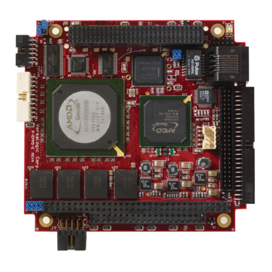
Page 1: Reference Manual
Reference Manual DOC. REV. 3/17/2009 EPM-5 (Puma) AMD GX Based SBC with Ethernet, Video, and PC/104- Plus interface... - Page 2 All Rights Reserved Notice: Although every effort has been made to ensure this document is error-free, VersaLogic makes no representations or warranties with respect to this product and specifically disclaims any implied warranties of merchantability or fitness for any particular purpose.
- Page 3 Data sheets and manufacturers’ links for chips used in this product BIOS information and upgrades Utility routines and benchmark software Note: This is a private page for EPM-5 users that can be accessed only be entering this address directly. It cannot be reached from the VersaLogic homepage. EPM-5 Reference manual...
-
Page 4: Table Of Contents
Side Profile ......................14 Hardware Assembly..................... 15 Stack Arrangement Example ................15 External Connectors......................16 EPM-5 Connector Locations – Top ..............16 EPM-5 Connector Locations – Bottom..............17 EPM-5 Connector Functions and Interface Cables..........18 Connector Locations – CBL/CBR-5010.............. 19 CBL/CBR-5010 Connector Functions and Mating Connectors ...... - Page 5 PC/104 Memory Support ..................38 IRQ Support......................38 DMA Support ...................... 38 System Resources and Maps..................39 Memory Map ........................39 I/O Map..........................39 Interrupt Configuration ..................... 40 Special Registers ......................41 Special Control Register ....................41 EPM-5 Reference manual...
- Page 6 Contents Revision Indicator Register....................42 Jumper and Status Register....................43 RS-485/422 Transmit/Receive Control Register .............. 44 Appendix A – References ..................... 45 Appendix B – Generated Frequencies ................ 46 EPM-5 Reference Manual...
-
Page 7: Introduction
5V supply to the USB ports. EPM-5 boards are subjected to 100% functional testing and are backed by a limited two-year warranty. Careful parts sourcing and US-based technical support ensure the highest possible quality, reliability, service and product longevity for this exceptional SBC. -
Page 8: Technical Specifications
PC/104 (ISA): 8MHz Compatibility: PC/104 – Partial compliance (See PC/104 expansion bus) Embedded-PCI (PC/104-Plus) – full compliance, 3.3V signaling Weight: EPM-5g – 0.115 kg (0.253 lbs) EPM-5h – 0.125 kb (0.275 lbs) Specifications are subject to change without notice. EPM-5 Reference Manual... -
Page 9: Epm-5 Block Diagrams
Introduction EPM-5 Block Diagrams SDRAM Address, Data, Control Analog RGB FP LVDS National SDCLKS Digital RGB DS90C383A FS2 JTAG Pads System Clocking (MK1491-09) 14.318 MHz Intel 33 MHz 82155ER 24.576 MHz 10/100M Audio 25.000 MHz USB 2.0 CS5536 (4 Ports) I/O Companion 48.000 MHz... - Page 10 1.2V @ 200 mA LTC3025 CS5536 VCORE 3.3V @ 1.4A LTC3412 CPU and CS5536 VIO I809 POR TO CS5536 RI1# (RING INDICATOR) PWRBTN# (SOFT PWR BUTTON) PWR CONTROL EIRQ1_3V (EXTERNAL WAKE) WORK_AUX Figure 2. Power Control Block Diagram EPM-5 Reference Manual...
-
Page 11: Rohs Compliance
HS C OMPLIANT ABLES Adapter cables for the EPM-5 are available in RoHS compliant and RoHS noncompliant versions. Compliance or noncompliance is indicated by the part number prefix. “CBR” indicates RoHS compliance. “CBL” indicates RoHS noncompliance. For applications that require RoHS compliance, use only the RoHS compliant (“CBR”... -
Page 12: Lithium Battery
CMOS RAM to become corrupted through careless handling (while changing the CompactFlash module), resulting in CMOS resetting to factory defaults. EPM-5 Reference Manual... -
Page 13: Technical Support
Introduction Technical Support If you are unable to solve a problem after reading this manual please visit the EPM-5 Product Support web page at http://www.VersaLogic.com/private/pumasupport.asp. If you have further questions, contact VersaLogic technical support at (541) 485-8575. VersaLogic technical support engineers are also available via e-mail at Support@VersaLogic.com. -
Page 14: Configuration And Setup
Inspect the system visually for any damaged that may have occurred in shipping. Contact Support@VersaLogic.com immediately if any items are damaged or missing. Gather all the peripheral devices you plan to attach to the EPM-5 and their interface and power cables. - Page 15 CD-ROM drive to the connectors on the cable. If the hard drive is 3.5”, use the 2mm to 0.1” adapter CBL/CBR-4405 to attach the IDE cable. Attach an ATX power cable to any 3.5” drive (hard drive or CD-ROM drive). EPM-5 Reference Manual...
- Page 16 3. Review Configuration Before you power up the system, double check all the connections. Make sure all cables are oriented correctly and that adequate power will be supplied to the EPM-5 and peripheral devices. 4. Power On Turn on the ATX power supply and the video monitor.
-
Page 17: Cmos Setup
Configuration and Setup CMOS Setup The default CMOS Setup parameters for the EPM-5 are shown below. See VersaLogic KnowledgeBase article VT1458 – EPM-5 CMOS Setup Reference for more information about these parameters. Basic CMOS Configuration +------------------------------------------------------------------------------+ System BIOS Setup - Basic CMOS Configuration (C) 2005 General Software, Inc. -
Page 18: Operating System Installation
Operating System Installation The standard PC architecture used on the EPM-5 makes the installation and use of most of the standard x86 processor-based operating systems very simple. The operating systems listed on the... -
Page 19: Physical Details
Physical Details Dimensions and Mounting The EPM-5 complies with all PC/104-Plus standards. Dimensions are given below to help with pre-production planning and layout. 3.575 3.375 3.275 3.175 0.20 0.10 0.00 -0.20 Figure 4.EPM-5 Dimensions and Mounting Holes (Not to scale. All dimensions in inches.) -
Page 20: Side Profile
Physical Details ROFILE 0.50 0.44 0.06 0.40 0.44 Figure 5. EPM-5 Side Profile (Not to scale. All dimensions in inches.) 5.50 5.10 1.575 1.875 1.175 1.95 1.38 0.065 Figure 6. CBL/CBR-5010 Dimensions and Mounting Holes (Not to scale. All dimensions in inches.) -
Page 21: Hardware Assembly
ARDWARE SSEMBLY The EPM-5 uses pass-through PC/104 and PC/104-Plus connectors so that expansion modules can be added to the top or bottom of the stack. PC/104 (ISA) modules must not be positioned between the EPM-5 and any PC/104-Plus (PCI) modules on the stack. -
Page 22: External Connectors
12 11 Video Output PC/104-Plus Ethernet Battery 20 19 Standard I/O (COM, USB, timer inputs, reset, speaker, Audio LED) PC/104 43 44 49 50 Main = Pin 1 Power Figure 8. Connector Locations (Top) (Not to scale.) EPM-5 Reference Manual... -
Page 23: Epm-5 Connector Locations - Bottom
Physical Details EPM-5 C – B ONNECTOR OCATIONS OTTOM PC-104-Plus pass-through male CompactFlash LVDS PC-104 = Pin 1 pass-through male Figure 9. Connector Locations (Bottom) (Not to scale.) EPM-5 Reference Manual... -
Page 24: Epm-5 Connector Functions And Interface Cables
NTERFACE ABLES Table 1 provides information about the function, mating connectors, and transition cables for EPM-5 connectors. Page numbers indicate where a detailed pinout or further information is available. Note: Adapter cables for the EPM-5 are available in RoHS compliant and RoHS noncompliant versions (see “RoHS Compliance”). -
Page 25: Connector Locations - Cbl/Cbr-5010
2mm, 50-pin, keyed, latching header ACPI Pushbutton Input Conta-Clip 10250.4 5-pin screw terminal COM1 Kycon K42-E9P/P-A4N DB-9 male USB 0-3 USB Type A USB Type A COM4 Conta-Clip 10250.4 5-pin screw terminal COM3 Conta-Clip 10250.4 5-pin screw terminal EPM-5 Reference Manual... -
Page 26: Jumper Blocks
Physical Details Jumper Blocks UMPERS HIPPED ONFIGURATION V1 V2 Figure 11. Jumper Block Locations EPM-5 Reference Manual... -
Page 27: Jumper Summary
Standard Erase Operation CMOS Warning: Use care when handling the EPM-5 not to short the V2 pins accidentally, which may cause CMOS to revert to factory settings. V3[1-2] COM3 RS-422/485 Termination In – Line A and B terminated with 127 Ohms Out –... -
Page 28: System Features
Power Supply OWER ONNECTORS Main power is applied to the EPM-5 through a 10-pin polarized connector, with mating connector Berg 69176-010 (Housing) + Berg 47715-000 (Pins). See the table below for connector pinout and page 16 for location information. Warning! To prevent severe and possibly irreparable damage to the system, it is critical that the power connectors are wired correctly. -
Page 29: Power Requirements
OWER EQUIREMENTS The EPM-5 requires only +5 volts (±5%) for proper operation. The voltage required for the RS-232 ports is generated with an on-board DC/DC converter. A variable low-voltage supply circuit provides power to the CPU and other on-board devices. -
Page 30: Cmos Ram
CMOS RAM and the Real-Time Clock. When clearing CMOS RAM: 1) Power off the EPM-5. 2) Install the jumper on V2[2-3] and leave it for four seconds. 3) Move the jumper to back to V2[1-2]. 4) Power on the EPM-5. -
Page 31: Acpi Power Management
System Features ACPI Power Management The EPM-5 supports the Advanced Configuration and Power Interface (ACPI) “S3 Sleeping State,” also known as “standby” or “suspend to RAM” mode. Wakeup is accomplished via a TTL-level input or pushbutton (or relay attached to the pushbutton interface). Power consumption in standby mode is under 1 watt. -
Page 32: Wakeup
A pushbutton or relay can be attached to connector J2 on the CBL/CBR-5010 utility board. Pin 3 is ground, and pin 4 (or pin 40 of motherboard utility connector J8) is the pushbutton input. A 3.3V or 5V TTL signal can also drive pin 4. This circuit on the EPM-5 motherboard has a 10k pull-up resistor. -
Page 33: Interfaces And Connectors
Interfaces and Connectors Serial Ports The EPM-5 features three on-board 16550-based serial channels located at standard PC I/O addresses. Connector J8 provides interfaces to the COM ports. See Table 6 on page 18 for COM port signal and pinout information. -
Page 34: Ide Hard Drive / Cd-Rom Interfaces
DD14 Data bus bit 14 Chip select 1 Data bus bit 0 DASP- DD15 Data bus bit 15 Ground Ground Ground Ground Power +5.0 V Power +5.0 V PDMARQ DMA request Ground Ground Ground Ground No connection EPM-5 Reference Manual... -
Page 35: J8 Utility Connector
+5V (Protected) Speaker RxD+ TxD/RxD+ Speaker Drive RxD– TxD/RxD– PBRESET Ground – Ground Ground Pushbutton Reset USB0 Ground +5V (Protected) Channel 0 Data + Channel 0 Data - Note: Do not connect to these pins in RS-485 mode. EPM-5 Reference Manual... -
Page 36: Usb Interface
USB I NTERFACE Connector J8 includes interfaces for four USB ports. The USB interface on the EPM-5 is UHCI (Universal Host Controller Interface) and EHCI (Enhance Host Controller Interface) compatible, which provides a common industry software/hardware interface. There are four USB connectors on the CBL/CBR-5010 breakout board. -
Page 37: Parallel Port
Interfaces and Connectors Parallel Port The EPM-5 includes a standard bi-directional/EPP/ECP compatible LPT port which resides at the PC standard address of 378h. The port can be enabled or disabled and interrupt assignments can be made via CMOS Setup. The LPT mode is also set via CMOS Setup. -
Page 38: Video Interface
Interfaces and Connectors Video Interface An on-board video controller integrated into the chipset provides high performance video output for the EPM-5. (The EPM-5 can also be operated without video card attached. See “Console Redirection.”) ONFIGURATION The EPM-5 uses a shared-memory architecture. This allows the video controller to use 16 Mega- bytes of system DRAM for video RAM. -
Page 39: Lvds Flat Panel Display Connector
ISPLAY ONNECTOR The integrated LVDS Flat Panel Display in the EPM-5 is an ANSI/TIA/EIA-644-1995 specification-compliant interface. It can support up to 24 bits of RGB pixel data plus 3 bits of timing control (HSYNC/VSYNC/DE) on the 4 differential data output pairs. The LVDS clock frequency ranges from 25 MHz to 85 MHz. -
Page 40: Compatible Lvds Panel Displays
Compatible with DOS or Windows Generic VGA driver, but not the GX Windows driver. ONSOLE EDIRECTION The EPM-5 can be operated without using the onboard video output by redirecting the console to COM1. CMOS Setup and some operating systems such as DOS can use this console for user interaction. - Page 41 The following diagram illustrates a typical DB9 to DB9 RS-232 null modem adapter. System 1 <--> System 2 Name Name ------------------------------------ <--> <--> <--> <--> <--> <--> Pins 7 and 8 are shorted together on each connector. Unlisted pins have no connection. EPM-5 Reference Manual...
-
Page 42: Ethernet Interface
Interfaces and Connectors Ethernet Interface The EPM-5 features an on-board Ethernet controller. This controller is the Intel 82551ER Fast Ethernet controller. While this controller is not NE2000-compatible, it is widely supported. Drivers are readily available to support a variety of operating systems. See VersaLogic website for latest OS support. -
Page 43: Audio
Interfaces and Connectors Audio The audio interface on the EPM-5 is implemented using the Analog Devices AD1981B Audio Codec. This interface is AC ’97 2.3 compatible. Drivers are available for most Windows-based operating systems. To obtain the most current versions, consult the EPM-5 product support page at http://www.VersaLogic.com/private/pumasupport.asp. -
Page 44: Pc/104 Expansion Bus
Interfaces and Connectors PC/104 Expansion Bus EPM-5 has limited support of the PC/104 bus. Most PC/104 cards will work, but be sure to check the requirements of your PC/104 card against the list below. PC/104 I/O S UPPORT The following I/O ranges are supported: 100h –... -
Page 45: System Resources And Maps
System Resources and Maps Memory Map The lower 1 MB memory map of the EPM-5 is arranged as shown in the following table. Various blocks of memory space between C0000h and FFFFFh can be shadowed. The CMOS setup is used to enable or disable this feature. -
Page 46: Interrupt Configuration
IRQ3 (B25) was bonded to PC/104 IRQ7 (B21), and PC/104 IRQ4 (B24) to PC/104 IRQ11 (D4). Though the EPM-5 is not equipped with a standard keyboard (IRQ1), floppy disk (IRQ6), or mouse (IRQ12), the BIOS infrastructure makes it appear they exist for DOS and older operating systems. -
Page 47: Special Registers
Indicates CPU temperature. CPU temperature is below value set in the CMOS setup CPU temperature is above value set in the CMOS setup Note: This bit is a read-only bit. D4-D0 Reserved Reserved — These bits have no function. EPM-5 Reference Manual... -
Page 48: Revision Indicator Register
Special Registers Revision Indicator Register REVIND (READ ONLY) 1D1h REV1 REV0 This register is used to indicate the revision level of the EPM-5. Table 17: Revision Indicator Register Bit Assignments Mnemonic Description D7-D3 Product Code — These bits are hard-coded to represent the product type. The EPM-5 always reads as 00011. -
Page 49: Jumper And Status Register
System BIOS Selection — Indicates the status of jumper. Jumper out, Master System BIOS selected. Jumper in, Run Time System BIOS selected. Note: This is a read-only bit. D4-D0 Reserved Reserved — These bits have no function. EPM-5 Reference Manual... -
Page 50: Rs-485/422 Transmit/Receive Control Register
Note: This is a write-only bit. Note: On the EPM-5 Rev 5.00 and earlier boards, this register was read/write. Customers using COM3 or COM4 in RS-422 or RS-485 modes should review their driver code to ensure the control register at 1DAh is used as a write-only register. -
Page 51: Appendix A - References
Intel 82551ER Video Controller In chipset. PC/104 Specification PC/104 Consortium PC/104 Resource Guide PC/104-Plus Specification VersaLogic Corporation PC/104 Resource Guide General PC Documentation Microsoft Press The Programmer’s PC Sourcebook General PC Documentation Powell’s Books The Undocumented PC EPM-5 Reference Manual... -
Page 52: Appendix B - Generated Frequencies
Appendix B – Generated Frequencies The following frequencies on the EPM-5 board can be measured for EMI/EMC testing. Table 20: Generated Frequencies Component Frequencies Notes 10/100 Ethernet 25 MHz Y1 crystal, U7 82551ER chip. 32.768 kHz Y2 crystal, U13A CS5536 chip.
Need help?
Do you have a question about the EPM-5 and is the answer not in the manual?
Questions and answers