
Related Manuals for Vertiv NetSure 801 CAA Series


Summary of Contents for Vertiv NetSure 801 CAA Series
- Page 1 NetSure 801 CAA Series Power Supply System Instruction Manual Version: V1.0 Revision date: August 16, 2018 BOM: 31013828...
- Page 2 NetReach™, NetSure™ and NetXtend™ are trademarks of Vertiv Energy Systems, Inc. All other trademarks are the property of their respective owners. © 2018 Vertiv Energy Systems, Inc. All rights reserved. Vertiv | NetSure 801 CAA Series Power Supply System Instruction Manual...
-
Page 3: Table Of Contents
Installation Checklist ................ 60 Installing Rectifier and Controller ............ 61 Installing Rectifier ................. 61 Installing Controller ................62 The Installation and Wiring of The Controller IB2 Extension Board ..................... 63 Vertiv | NetSure 801 CAA Series Power Supply System Instruction Manual... - Page 4 Appendix 1 Technical Parameters ............. 113 Appendix 2 Alarm list ................. 116 Appendix 3 ENGINEERING DESIGN DIAGRAM ........122 APPENDIX 4 WIRING DIAGRAM ............138 Appendix 5 SPARE PARTS ..............156 Vertiv | NetSure 801 CAA Series Power Supply System Instruction Manual...
-
Page 5: Safety Precautions
When operating Vertiv products, the safety rules in the industry, the general safety points and special safety instructions specified in this book must be strictly observed. -
Page 6: Battery
Remove the watch, bracelet, bangle, ring, and other metal objects on the wrist. Use special insulated tools. Use eye protection device, and take preventive measures. Wear rubber gloves and apron to guard against electrolyte overflow. Vertiv | NetSure 801 CAA Series Power Supply System Instruction Manual... -
Page 7: Others
Never touch the connectors of the boards when holding the boards. V. Binding signal lines NOTICE! Signal lines should be bound separately from heavy current and high voltage lines, with binding interval no less than 150mm. Vertiv | NetSure 801 CAA Series Power Supply System Instruction Manual... -
Page 8: Overview
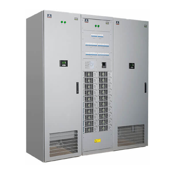
OVERVIEW The NetSure 801 CAA series power supply system (power supply system for short) is a new generation of telecom power supply with exceptional reliability and performance. It is designed by Vertiv incorporating years of experience in development and equipment operation on power network. -
Page 9: Components
Components Rectifier The system uses rectifier R48-5800A/R48-5800e, the frame structure of which mainly consists of panel, enclosure, handle, and so on, as shown in Figure 3. Vertiv | NetSure 801 CAA Series Power Supply System Instruction Manual... - Page 10 (output current > 100A), indicators the tenth LED will blink. If the output current of the rectifier is smaller than 2A, no current indicator will be on Vertiv | NetSure 801 CAA Series Power Supply System Instruction Manual...
-
Page 11: Controller
PD380/630AFA-A-Y1 and PD380/630AFH-A-YF. The appearances of the AC distribution cabinets are the same, as shown in Figure 5. Figure 5: Appearance of AC distribution cabinet Indicator Power distribution LCD Vertiv | NetSure 801 CAA Series Power Supply System Instruction Manual... - Page 12 The internal structure of AC distribution cabinet PD380/400AFH-A-Y1 is shown in Figure 6. Figure 6: PD380/400AFH-A-Y1 AC distribution cabinet Knife-blade switch AC output MCB (a) Front view (front door open) Neutral busbar Earth busbar (b) Rear view (rear door open) Vertiv | NetSure 801 CAA Series Power Supply System Instruction Manual...
- Page 13 Vertiv | NetSure 801 CAA Series Power Supply System Instruction Manual...
- Page 14 The internal structure of AC distribution cabinet PD380/630AFH-A-Y1 is shown in Figure 7. Figure 7: PD380/630AFH-A-Y1 AC distribution cabinet Knife-blade switch SPD MCB Class C SPD AC output MCB (a) Front view (front door open) Vertiv | NetSure 801 CAA Series Power Supply System Instruction Manual...
- Page 15 The internal structure of AC distribution cabinet PD380/630AFA-A-Y1 is shown in Figure 8. Figure 8: PD380/630AFA-A-Y1 AC distribution cabinet ATS controller AC output MCB (a) Front view (front door open) Vertiv | NetSure 801 CAA Series Power Supply System Instruction Manual...
-
Page 16: Dc Distribution Cabinet
The DC distribution cabinet is available in seven models: PD48/1600DF-A-Y1, PD48/1600DF-A-Y2, PD48/1600DF-A-YF, PD48/2500DF-A-Y1, PD48/2500DF-A-Y2, PD48/2500DF-A-Y3 and PD48/2500DF- A-YF. The appearances of the DC distribution cabinets are the same, as shown in Figure 9. Vertiv | NetSure 801 CAA Series Power Supply System Instruction Manual... - Page 17 Figure 9: Appearance of DC distribution cabinet Indicator Power distribution LCD Vertiv | NetSure 801 CAA Series Power Supply System Instruction Manual...
- Page 18 The internal structure of PD48/1600DF-A-Y1 DC distribution cabinet is shown in Figure 10. Figure 10: PD48/1600DF-A-Y1 DC distribution cabinet Battery fuse Battery shunt Output shunt Power distribution monitoring Output fuse (a) Front view (open front door) Vertiv | NetSure 801 CAA Series Power Supply System Instruction Manual...
- Page 19 The internal structure of DC distribution cabinet PD48/1600DF-A-Y2 is shown in Figure 11. Figure 11: PD48/1600DF-A-Y2 DC distribution cabinet Battery fuse Battery shunt Output shunt Power distribution monitoring Output fuse (a) Front view (open front door) Vertiv | NetSure 801 CAA Series Power Supply System Instruction Manual...
- Page 20 Total load current hall sensor DC SPD (b) Rear view (remove rear door) Vertiv | NetSure 801 CAA Series Power Supply System Instruction Manual...
- Page 21 Figure 12: PD48/2500DF-A-Y1 DC distribution cabinet Battery fuse Battery shunt Output shunt Power distribution monitoring Output fuse (a) Front view (open front door) Total load current hall sensor DC SPD Vertiv | NetSure 801 CAA Series Power Supply System Instruction Manual...
- Page 22 The internal structure of DC distribution cabinet PD48/2500DF-A-Y2 is shown in Figure 13. Figure 13: PD48/2500DF-A-Y2 DC distribution cabinet Battery fuse Battery shunt Output shunt Power distribution monitoring Output fuse (a) Front view (open front door) Vertiv | NetSure 801 CAA Series Power Supply System Instruction Manual...
- Page 23 The internal structure of DC distribution cabinet PD48/2500DF-A-Y3 is shown in Figure 14. Figure 14: PD48/2500DF-A-Y3 DC distribution cabinet Battery fuse Battery shunt Output shunt Power distribution monitoring Output fuse (a) Front view (open front door) Vertiv | NetSure 801 CAA Series Power Supply System Instruction Manual...
-
Page 24: Rectifier Cabinet
The structure of rectifier cabinet Rack1000-A is shown in Figure 15, the structure of rectifier cabinet Rack1500-A is shown in Figure 16 and the structure of rectifier cabinet Rack2000-A is shown in Figure 17. Vertiv | NetSure 801 CAA Series Power Supply System Instruction Manual... - Page 25 Figure 15: Rack1000-A rectifier cabinet Rectifier input MCB Controller Rectifier Vertiv | NetSure 801 CAA Series Power Supply System Instruction Manual...
- Page 26 Figure 16: Rack1500-A rectifier cabinet Rectifier input MCB Controller Rectifier Figure 17: Rack2000-A rectifier cabinet Rectifier input MCB Controller Rectifier Vertiv | NetSure 801 CAA Series Power Supply System Instruction Manual...
- Page 27 It is used to control the switchover automatic between the 2 mains inputs. This switch can be placed in 2 PD380/630AFA AC cabinet positions: ‘I’ and ‘II’, respectively representing mains input 1 and mains input 2 Vertiv | NetSure 801 CAA Series Power Supply System Instruction Manual...
- Page 28 NAME FUNCTION CABINET Output MCB Configured according to custermer requirement AC cabinet Output fuse Configured according to custermer requirement DC cabinet Vertiv | NetSure 801 CAA Series Power Supply System Instruction Manual...
-
Page 29: Installation Preparation
NOTE! To prevent electric coupling, AC cables should be run separate from DC cables and signal cables. Installation surface The installation surface is supposed to be cement floor or incombustible metal subrack. Vertiv | NetSure 801 CAA Series Power Supply System Instruction Manual... - Page 30 Refer to Figure 18 for the above requirements. No less than 0.2m of clearance should be kept between the battery and the wall, and no less than 0.8m of clearance should be kept between batteries. Figure 18: Locating cabinet Vertiv | NetSure 801 CAA Series Power Supply System Instruction Manual...
- Page 31 Because the power supply system is relatively heavy, the weight capacity of the equipment room should meet relative requirements and is determined based on the equipment configuration. Vertiv | NetSure 801 CAA Series Power Supply System Instruction Manual...
-
Page 32: Power Supply
PD380/400AFH-A-Y1 AC distribution cabinet is not supposed to be directly connected to the secondary side of a transformer with capacity greater than 800kVA. An extra distribution cabinet should be used between PD380/400AFH-A-Y1 AC distribution cabinet and the transformer for Vertiv | NetSure 801 CAA Series Power Supply System Instruction Manual... -
Page 33: Safety Protection
Class-B SPD. The SPDs should be inspected periodically to ensure their normal operation. Figure 20: Diagram of SPD mounting & system earthing Vertiv | NetSure 801 CAA Series Power Supply System Instruction Manual... -
Page 34: Equipment Running Environment Checklist
Note: the content in the table is adapted from Installation Design Specifications for Communication Power Supply Equipment Equipment Running Environment Checklist The equipment running environment checklist is given in Table 5. Vertiv | NetSure 801 CAA Series Power Supply System Instruction Manual... - Page 35 According to specifications Yes/No Colour code of DC load cables According to specifications Yes/No Sectional area of DC distribution According to requirements Yes/No cables Earth wiring According to specifications Yes/No Vertiv | NetSure 801 CAA Series Power Supply System Instruction Manual...
-
Page 36: Storage Conditions
Large side door of the rectifier Used for sealing the lower part of 21502330 cabinet rectifier cabinet side 21502332 Small side door of the rectifier Used for sealing the upper part of Vertiv | NetSure 801 CAA Series Power Supply System Instruction Manual... - Page 37 External parallel copper bar the top of the cabinet. Applicable 21505274 component of the rectifier for external paralleling, no internal cabinet paralleling and the rectifier cabinet – DC cabinet spaced placement Vertiv | NetSure 801 CAA Series Power Supply System Instruction Manual...
- Page 38 The CSA of DC cable depends on the current flowing through the cable and the allowable voltage drop. To select the battery cable CSA, see Table 7. Select the load cable CSA according to the Table Vertiv | NetSure 801 CAA Series Power Supply System Instruction Manual...
- Page 39 160A use M8 OT - shape cable connectors. The load MCBs uses the M8 OT - shape or pipe - shape cable connectors. Vertiv | NetSure 801 CAA Series Power Supply System Instruction Manual...
-
Page 40: Unpacking Inspection
4. Check the goods according to the packing list and equipment configuration and technical requirements. Unpacking inspection To ensure smooth installation, the equipment must be carefully inspected when it is unpacked. The checking should include: Vertiv | NetSure 801 CAA Series Power Supply System Instruction Manual... - Page 41 5. The conditions of the goods through visual inspection. For example, check if the cabinet and case are damaged, if the cabinet and case have regained moisture; shake gently the rectifiers and controller to check if the parts and connections have been loosened during transportation. Vertiv | NetSure 801 CAA Series Power Supply System Instruction Manual...
-
Page 42: Installation
INSTALLATION This chapter introduces the installation and connection of NetSure 801 CAA series power supply system (power supply system for short). Cabinet Installation Cabinet Placement Before installing and connecting the power system, make sure the layout of each cabinet in the power system, especially the placement of DC cabinet and rectifier cabinet. -
Page 43: Mounting Large Side Door And Small Side Door
Vertiv | NetSure 801 CAA Series Power Supply System Instruction Manual... - Page 44 (a) Installation size of the AC distribution cabinet 4-φ1 4 (b) Installation size of the rectifier cabinet 4-φ1 8 603.5 396.5 600 (c) Installation size of the DC distribution cabinet Vertiv | NetSure 801 CAA Series Power Supply System Instruction Manual...
-
Page 45: Installation On Supporting Rack
Spring washer Plain washer Plain washer Expansive pipe Expansive pipe Step 2: fix the cabinet Install the power supply cabinet on the supporting rack, as shown in Figure 24. Vertiv | NetSure 801 CAA Series Power Supply System Instruction Manual... -
Page 46: Parallel Connection Between Cabinets
Take parallel connections between a rectifier cabinet and a DC distribution cabinet for example, the connection procedures are as follows: 1. Remove the upper side doors between the rectifier cabinet and the DC distribution cabinet. 2. Install the parallel copper bar nut kit. Vertiv | NetSure 801 CAA Series Power Supply System Instruction Manual... - Page 47 3). Install the parallel board between cabinets, connect one side with nut kit (adjacent to the external parallel connection port) to the parallel board in the rectifier cabinet, as shown in Figure Vertiv | NetSure 801 CAA Series Power Supply System Instruction Manual...
- Page 48 Positive parallel board in the DC cabinet in the rectifier cabinet Nut kit Parallel board between the cabinets Negative parallel board Negative parallel board in the DC cabinet in the rectifier cabinet Front View Vertiv | NetSure 801 CAA Series Power Supply System Instruction Manual...
-
Page 49: Connecting Power Cables
The accessory cables used in cable connection are given in Table 10. Among which, 1 ~ 6 are power cables between cabinets, 7 ~ 11 are communication cables between cabinets. The AC input cable, battery cable and load cable should be prepared by user themselves. Vertiv | NetSure 801 CAA Series Power Supply System Instruction Manual... -
Page 50: Connecting Earth Cable
1. Use the earth cable to connect the earth bolt at the rear lower part of the rectifier cabinet to the earth bar of the AC distribution cabinet, see Figure 30 and Figure 31. Vertiv | NetSure 801 CAA Series Power Supply System Instruction Manual... - Page 51 2. Use the earth cable to connect the earth bolt of the DC distribution cabinet to the earth bar of the AC distribution cabinet. The earth terminal of DC distribution cabinet is as shown in Figure 32. Vertiv | NetSure 801 CAA Series Power Supply System Instruction Manual...
-
Page 52: Connecting Cables Between Rectifier Cabinet And Ac Distribution Cabinet
AC input cables. Otherwise users need to prepare armored cables by themselves. If the system capacity exceeds 2000A, users need to prepare extra cables. The cable specification cannot greater than 50mm . The wiring is shown in Figure 33. Vertiv | NetSure 801 CAA Series Power Supply System Instruction Manual... - Page 53 Figure 34: AC input cable wiring (manually switch AC distribution cabinet, rear view) Input cable wiring area Output cable wiring area one Output cable wiring area two Top view Right view Front view Vertiv | NetSure 801 CAA Series Power Supply System Instruction Manual...
- Page 54 3. Connect the other end of the cable to the AC input terminal of the rectifier cabinet. The connection of AC input cables in rectifier cabinet is shown in Figure 36. Vertiv | NetSure 801 CAA Series Power Supply System Instruction Manual...
-
Page 55: Connecting Ac Input Cables
After the AC input cables are fed into the cabinet, connect them to the knife-blade switch or air breaker or ATS of the AC distribution cabinet, as shown in Figure 37 and Figure 38. Vertiv | NetSure 801 CAA Series Power Supply System Instruction Manual... - Page 56 Figure 37: Mains input cable connection to AC distribution cabinet (manually switch AC distribution cabinet, rear view) Vertiv | NetSure 801 CAA Series Power Supply System Instruction Manual...
-
Page 57: Connecting Dc Emergency Lighting Cables (Optional)
MCB, and the other end to the negative terminal of the emergency lighting, as shown in Figure 39. Vertiv | NetSure 801 CAA Series Power Supply System Instruction Manual... -
Page 58: Connecting Dc Load Cables
Connect one end of the negative cable to the output terminal of the fuse, and the other end of the positive cable to the positive copper bar of the DC distribution cabinet, as shown in Figure 41. Vertiv | NetSure 801 CAA Series Power Supply System Instruction Manual... -
Page 59: Connecting Battery Cables
Connect the cables to the battery when the DC distribution is to be initially tested, as shown in Figure 42. NOTE! The battery negative cables should be connected to the two battery fuses, not the single one. Vertiv | NetSure 801 CAA Series Power Supply System Instruction Manual... -
Page 60: Installation Checklist
Yes/No SPD earth, DC power earth and protective earth are connected correctly Yes/No Leeway is left for the length of connection cable and the cable wiring is Yes/No covert Vertiv | NetSure 801 CAA Series Power Supply System Instruction Manual... -
Page 61: Installing Rectifier And Controller
3. Tighten the bolts on the handle to fix the rectifier on the rack, as shown in Figure 43 (c) and Figure 43 (d). Figure 43: Installing rectifier Fixing screw Handle Slide switch Vertiv | NetSure 801 CAA Series Power Supply System Instruction Manual... -
Page 62: Installing Controller
Figure 45: Controller Panel diagram Captive screw Captive screw Handle Handle 3. Push the controller into the correct position, and then fix the screws on the panel, as shown in Figure 46. Vertiv | NetSure 801 CAA Series Power Supply System Instruction Manual... -
Page 63: The Installation And Wiring Of The Controller Ib2 Extension Board
IB2 expansion board. Use four screws IB2 extension board fix the installation components, as shown in Figure 47. Figure 47: IB2 extension board Cover plate Signal extension board RS232 port Vertiv | NetSure 801 CAA Series Power Supply System Instruction Manual... - Page 64 Digital input 2- DI2+ Digital input 2+ DI3- Digital input 3- DI3+ Digital input 3+ DI4- Digital input 4- DI4+ Digital input 4+ DI5- Digital input 5- DI5+ Digital input 5+ Vertiv | NetSure 801 CAA Series Power Supply System Instruction Manual...
- Page 65 According to Figure 48 and the silkscreen, connect the signal cables to the corresponding terminals DI1~8 on IB2 board. The connection in Figure 48 illustrates the connection of input terminal DI1. Vertiv | NetSure 801 CAA Series Power Supply System Instruction Manual...
-
Page 66: Connecting Communication Cables And Auxiliary Power Cable
CAN communication and connection cables according to Figure 51. When the controller mounted to the rectifier on the right, connect the CAN communication cable between the rectifier cabinets as shown in Figure 51. Vertiv | NetSure 801 CAA Series Power Supply System Instruction Manual... - Page 67 监控 resistance resistance 模块 here here Controller Rectifier Rectifier Rectifier Rectifier Rectifier Rectifier cabinet 3 cabinet 3 cabinet 2 cabinet 1 cabinet 1 cabinet 2 Vertiv | NetSure 801 CAA Series Power Supply System Instruction Manual...
-
Page 68: Connecting Spd Signal Parallel Connection Cable Of Rectifier Cabinet
Figure 55. Note that the main cabinet (the rectifier cabinet that installs the controller) can only connect the parallel cable with one terminal, and the terminal cabinet should be connected to the cabinet with shorting terminals. Vertiv | NetSure 801 CAA Series Power Supply System Instruction Manual... -
Page 69: Connecting Communication Cable Of Distribution Cabinet
For AC/DC distribution cabinet, reserved the 3 PIN plug-in connectors in the RS485 cables on the rear top of the cabinet, through the 3 PIN plug-in connectors connected RS485 cables of the distribution cabinets. Vertiv | NetSure 801 CAA Series Power Supply System Instruction Manual... - Page 70 Figure 58. If the cabinet number is different from Figure 58, increase or decrease the parallel cables between cabinets according to Figure 58. The connection of RS485 Vertiv | NetSure 801 CAA Series Power Supply System Instruction Manual...
-
Page 71: Installing Options
(black to black, brown to brown). Each AC cabinet corresponds to a DC cabinet, as shown in Figure 58. Figure 58: Connection diagram of NetSure 801 CAA series power system communication cable and 48V DC auxiliary power source cable (front view) - Page 72 4. The temperature probe should be placed in the battery room, which can reflect most of the battery temperature. When fixing, do not connect the temperature probe with other heating devices or metal conductors. Vertiv | NetSure 801 CAA Series Power Supply System Instruction Manual...
-
Page 73: Testing
After a while, the controller will display 53.5V rectifier output voltage and then turn off the MCB of this rectifier. Check the other rectifiers one by one through turning on and off the rectifier MCBs and see if they can work normally. Vertiv | NetSure 801 CAA Series Power Supply System Instruction Manual... - Page 74 Preliminary test of DC distribution and battery connection Please connect the battery to the system according to the following steps. 1. Measure the battery voltage with multimeter and keep a record. Vertiv | NetSure 801 CAA Series Power Supply System Instruction Manual...
-
Page 75: Setting Basic Parameters
Bits 1 to 4 are used to set the addresses of the AC distribution cabinet and DC distribution cabinet. Position ‘ON’ represents ‘0’, and ‘OFF’ represents ‘1’. The setting explanation of bits 1 to 4 is given in Table 14. Vertiv | NetSure 801 CAA Series Power Supply System Instruction Manual... -
Page 76: Setting Basic Parameters For Controller
AC screens set to the same address, then press simultaneously at the first screen to enter the parameter setting screen and reset the address, and press Enter to confirm. Figure 61: AC screen address Vertiv | NetSure 801 CAA Series Power Supply System Instruction Manual... - Page 77 At the controller first screen in DC cabinet, press ENT to enter the ‘Settings’ screen (password: 1), enter ‘Batt. Settings’-->’Shunt Qty:’, ‘Shunt Coef’ -->’Current’, set the battery shunt quantity and battery shunt coefficient of the DC cabinet. Figure 64: Setting battery shunt Vertiv | NetSure 801 CAA Series Power Supply System Instruction Manual...
- Page 78 PD380/400AFH would be 100. If any inconsistencies exist, set the parameters as above. Figure 66: AC settings AC Distrib1 AC Distrib1 Curr Trans Coef: Input Number: 1 60 Input Type: Cur Measurement: 3-Phase 3-Phase Input Number: Output Number: Vertiv | NetSure 801 CAA Series Power Supply System Instruction Manual...
- Page 79 7. Back to the setting screen, enter ‘DC Settings’-->’DC Distrib 1’…… ’DC Distrib n’, check whether the ‘Hall Coefficient’ is consistent with Table 19. If any inconsistencies exist, reset the parameters according to Table 19. Vertiv | NetSure 801 CAA Series Power Supply System Instruction Manual...
- Page 80 64. If the number of output is less than 64, then there is no need to set the ‘Num of Output’. Figure 69: Setting number of output DC Distrib1 Branch Curr Coeff : Curr Output Num: Numof Output: Vertiv | NetSure 801 CAA Series Power Supply System Instruction Manual...
- Page 81 Number’ to 1 ~ 2 (if no temperature sensor is configured or the temperature compensation function needs to be canceled, then set the ‘Temp Number’ to ‘0’), as shown in Figure 74. Vertiv | NetSure 801 CAA Series Power Supply System Instruction Manual...
-
Page 82: Checking Alarm And Operation Status
Real time data will be displayed in contrast with the background in LCD. By reconnecting the communication cable, the system will recover automatically. Vertiv | NetSure 801 CAA Series Power Supply System Instruction Manual... - Page 83 53.5 V R: 380V 0.0 A 3600.0 A 3600.0 A S: 380V 100% T: 380V 100% 100% 系统使用容量: 0.0% Rect Cap Used: 22.3 % Rect Cap Used: 22.3 % 0.0% Vertiv | NetSure 801 CAA Series Power Supply System Instruction Manual...
-
Page 84: Testing Ac Distribution
AC Online: Status: Alarm Ctrl Mode: Manaul SPD: Failure 3. Press to enter the second screen, and check that the AC input current is consistent with actual input current. Vertiv | NetSure 801 CAA Series Power Supply System Instruction Manual... -
Page 85: Testing Dc Distribution
When the battery output voltage drops below the undervoltage alarm point, the controller will generate battery undervoltage alarm. Vertiv | NetSure 801 CAA Series Power Supply System Instruction Manual... -
Page 86: Access Controller Through Web
LVD1 : LVD 1 Reconnect By now, the system test is completed and the power supply system is in normal operation. Access Controller Through Web Login procedures are as follows: Vertiv | NetSure 801 CAA Series Power Supply System Instruction Manual... - Page 87 1. To log in the controller, double-click the icon of IE to run the software, click the menus of Tools -> Internet Options and then click the Connections button to pop up the interface shown in Figure 89. Vertiv | NetSure 801 CAA Series Power Supply System Instruction Manual...
- Page 88 If the controller is connected to Internet and the user computer is connected to the intranet, the user cannot disable the proxy, otherwise you will have no access to the controller. Vertiv | NetSure 801 CAA Series Power Supply System Instruction Manual...
- Page 89 4. Click on the Settings button. The following window opens, as shown in Figure 92. In the Settings window, choose “Every time I visit the webpage” and click OK. Vertiv | NetSure 801 CAA Series Power Supply System Instruction Manual...
- Page 90 Figure 92: Temporary internet files and history settings 5. In the “Internet Options” window, select the Security tab, as shown in Figure 93. Figure 93: Security tab Vertiv | NetSure 801 CAA Series Power Supply System Instruction Manual...
- Page 91 NOTE! Please check that you are using an address that starts with ‘https’, if not, but an address like http://10.39.3.200, then uncheck the ‘Require server verification (https:) for all sites in the zone:’ box. Vertiv | NetSure 801 CAA Series Power Supply System Instruction Manual...
- Page 92 The following Web Interface Login window opens, as shown in Figure 96. Enter a valid User Name and Password, and then click LOGIN. By default, the “User Name” is "admin" and the “Password” is “1”. Figure 96: Login the controller Vertiv | NetSure 801 CAA Series Power Supply System Instruction Manual...
- Page 93 10. Control the boost/float and rectifier switch, check whether the control function is correct. 11. Simulate fault alarms on the power system, and then check whether corresponding alarms are displayed in the homepage. Vertiv | NetSure 801 CAA Series Power Supply System Instruction Manual...
-
Page 94: Operation
3. Press ◄ or ► in the ‘DC distribution’ to view display content 5 ~ 30. 4. Press ▲ or ▼ at any screen to adjust the cursor position Vertiv | NetSure 801 CAA Series Power Supply System Instruction Manual... - Page 95 2. At any sub-menu of the main menu screen, press the ESC key repeatedly to return to the higher- level menu, and ultimately return to the main menu screen. Vertiv | NetSure 801 CAA Series Power Supply System Instruction Manual...
-
Page 96: Controller Operation Of Rectifier Cabinet
Web control interface in the controller. 1. Refer to Access Controller Through Web to enter the Web homepage window. 2. Select ‘Power System’ tab, as shown in Figure 102. Vertiv | NetSure 801 CAA Series Power Supply System Instruction Manual... - Page 97 (i.e. rectifiers, converters), DC equipment, and battery. 3. Click on the ‘Rectifier’ icon to access the following window, as shown in Figure 103. Vertiv | NetSure 801 CAA Series Power Supply System Instruction Manual...
- Page 98 Displayed on the Rectifier Device Group status page are the individual rectifiers installed in the system. 4. Click an individual rectifier icon to display its status such as "Current Limit", "Valid Rated Current", etc., as shown in Figure 104. Vertiv | NetSure 801 CAA Series Power Supply System Instruction Manual...
- Page 99 ‘Set’ to confirm. 6. Click to go back to the individual rectifier status page, as shown in Figure 105. Figure 105: Individual rectifier settings page Vertiv | NetSure 801 CAA Series Power Supply System Instruction Manual...
-
Page 100: Adding Load
The rated current of the rectifier input MCB is 20A, and its breaking capacity is 6kA. Vertiv | NetSure 801 CAA Series Power Supply System Instruction Manual... -
Page 101: Maintenance
Electric soldering iron 1 piece Weld components Wash brush 1 piece Clean the equipment and dust inside boxes Vertiv | NetSure 801 CAA Series Power Supply System Instruction Manual... -
Page 102: Reference Technical Specification For Maintenance
Reference standards for AC, DC and earth resistance are shown in Table 25, Table 26 and Table 27. Vertiv | NetSure 801 CAA Series Power Supply System Instruction Manual... - Page 103 Microwave relay station, fiber relay station < 10 < 20 (may be up to 30 Microwave passive relay station in the case of high soil resistivity) Vertiv | NetSure 801 CAA Series Power Supply System Instruction Manual...
-
Page 104: Routine Maintenance Items
Alarm should be given out in case Alarm function alarm indicator or alarm of fault contact), module failure and DC fuse blowout (test shall be conducted on unload fuse) Vertiv | NetSure 801 CAA Series Power Supply System Instruction Manual... - Page 105 “telephone noise” measurement scale. The peak – peak noise can Vertiv | NetSure 801 CAA Series Power Supply System Instruction Manual...
- Page 106 70°C eter the temperature rise of the node. The measurement results should meet the temperature rise limitation and voltage drop limitation requirements Vertiv | NetSure 801 CAA Series Power Supply System Instruction Manual...
-
Page 107: Routine Maintenance
DC power supply status are similar to those for the streamlined logs of the AC power supply status. Log items include DC output voltage, current of main loads, charge/discharge voltage and current, total load current, etc. Vertiv | NetSure 801 CAA Series Power Supply System Instruction Manual... -
Page 108: Basic Inspection
High temperature or Decrease ambient ion for pyrotoxin is near to the temperature or remove the rectifie air intake of rectifier pyrotoxin The rectifier isn’t Reinsert rectifier absolutely inserted into Vertiv | NetSure 801 CAA Series Power Supply System Instruction Manual... - Page 109 NOTE! During the treatment of rectifier fault, delete the address code of the closed rectifier in the rectifier parameters setting through the controller. Refer to M831D Controller User Manual for deleting method. Vertiv | NetSure 801 CAA Series Power Supply System Instruction Manual...
-
Page 110: Replacing Rectifier
4. Disconnect the rectifier switch, put the slide switch on position, grasp the handles, and push the rectifier into cabinet slowly, until it stops, as shown in Figure 108. Figure 108: Replacing rectifier (1) Vertiv | NetSure 801 CAA Series Power Supply System Instruction Manual... -
Page 111: Emergency Treatment
In case of failure of AC power supply to rectifier due to AC distribution fault, the AC mains can be directly introduced into the input switch of the rectifier. Vertiv | NetSure 801 CAA Series Power Supply System Instruction Manual... - Page 112 They shall also prepare emergency management regulations and grave accidents rush-repair rules. Vertiv | NetSure 801 CAA Series Power Supply System Instruction Manual...
-
Page 113: Appendix 1 Technical Parameters
≤ 2 Rectifier R48-5800A, R48-5800e ≤ 8 Table 31: Technical parameters of AC distribution cabinet PARAMETER PARAMETER DESCRIPTION CATEGORY Operating -5°C ~ 40°C temperature Environmental -40°C ~ 70°C Storage Vertiv | NetSure 801 CAA Series Power Supply System Instruction Manual... - Page 114 No conductive dust or erosive gases. No possibility of Other explosion Rated input voltage 48Vdc DC input Input voltage range 42Vdc ~ 57.6Vdc (error: 0.3Vdc) Rated input current PD48/1600DF-A-Y1: 1600A;PD48/1600DF-A-Y2: 1600A Vertiv | NetSure 801 CAA Series Power Supply System Instruction Manual...
- Page 115 2000 (H) × 800 (W) × 600 (D) PD48/1600DF-A-Y1 ≤ 280, PD48/1600DF-A-Y2 ≤ 280 Mechanical PD48/2500DF-A-Y1 ≤ 290, PD48/2500DF-A-Y2 ≤ 290, parameters Weight (kg) PD48/2500DF-A-Y3 ≤ 290 PD48/2500DF-A-YF, PD48/1600DF-A-YF ≤ 290 Vertiv | NetSure 801 CAA Series Power Supply System Instruction Manual...
-
Page 116: Appendix 2 Alarm List
5A), then the current is unbalanced. If the alarm condition is met, there is a 50s delay. An exception: If the system has a LVD alarm, ‘System current unbalance’ alarm does not occur Vertiv | NetSure 801 CAA Series Power Supply System Instruction Manual... - Page 117 This alarm can only be ceased manually ECO Active Observation AllRectCommFail Major ECO Cycle Alarm Observation This alarm happens when Rectifier AC Failure Major Relay 4 rectifier AC power fails Vertiv | NetSure 801 CAA Series Power Supply System Instruction Manual...
- Page 118 The alarm happens during Auto EQ Observation auto boost charging The alarm happens during Cyclic EQ Observation timed boost charging The alarm happens when Dsch Curr Imb Observation discharging current is unbalanced Vertiv | NetSure 801 CAA Series Power Supply System Instruction Manual...
- Page 119 M2 Ubc/Ub Fail Critical Relay 2 M2 Uca/Uc Fail Critical Relay 2 M3 Uab/Ua Fail Critical Relay 2 M3 Ubc/Ub Fail Critical Relay 2 M3 Uca/Uc Fail Critical Relay 2 Vertiv | NetSure 801 CAA Series Power Supply System Instruction Manual...
- Page 120 Relay 3 T1 Under Temp Major Relay 3 T2 Under Temp Major Relay 3 T3 Under Temp Major Relay 3 T1 Sensor Fail Observation None T2 Sensor Fail Observation None Vertiv | NetSure 801 CAA Series Power Supply System Instruction Manual...
- Page 121 Alarm Alarm Related Alarm name Alarm description device category relay T3 Sensor Fail Observation None Vertiv | NetSure 801 CAA Series Power Supply System Instruction Manual...
-
Page 122: Appendix 3 Engineering Design Diagram
APPENDIX 3 ENGINEERING DESIGN DIAGRAM Engineering design diagram for AC distribution cabinet Figure 112: PD380/400AFH-A-Y1 engineering design diagram (front view, unit mm) 910.5 1060.5 1209.5 1359.5 2000.0 341.0 600.0 Vertiv | NetSure 801 CAA Series Power Supply System Instruction Manual... - Page 123 Figure 113: PD380/630AFH-A-Y1 engineering design diagram (rear view, unit mm) 364.5 724.5 2000.0 600.0 Vertiv | NetSure 801 CAA Series Power Supply System Instruction Manual...
- Page 124 Figure 114: PD380/630AFA-A-Y1 engineering design diagram (front view, unit mm) 910.5 1060.5 1210.5 1359.5 1509.5 2000.0 341.0 600.0 Vertiv | NetSure 801 CAA Series Power Supply System Instruction Manual...
- Page 125 Engineering design diagram for rectifier cabinet Figure 115: RACK2000-A engineering design diagram (unit mm) 389.7 156.7 1684 2000 RACK2000-A front view RACK2000-A rear view Vertiv | NetSure 801 CAA Series Power Supply System Instruction Manual...
- Page 126 Figure 116: RACK1500-A engineering design diagram (unit mm) 389.7 156.7 1684 2000 RACK1500-A front view RACK1500-A rear view Vertiv | NetSure 801 CAA Series Power Supply System Instruction Manual...
- Page 127 Figure 117: RACK1000-A engineering design diagram (unit mm) 156.7 1684 2000 RACK1000-A front view RACK1000-A rear view Vertiv | NetSure 801 CAA Series Power Supply System Instruction Manual...
- Page 128 Engineering design diagram for DC distribution cabinet Figure 118: PD48/1600DF-A-Y1 engineering design diagram (front view, unit mm) 475.5 1205 1642 Vertiv | NetSure 801 CAA Series Power Supply System Instruction Manual...
- Page 129 Figure 119: PD48/1600DF-A-Y1 engineering design diagram (rear view, unit mm) Vertiv | NetSure 801 CAA Series Power Supply System Instruction Manual...
- Page 130 Figure 120: PD48/1600DF-A-Y2 engineering design diagram (front view, unit mm) 475.5 1195 1741 Vertiv | NetSure 801 CAA Series Power Supply System Instruction Manual...
- Page 131 Figure 121: PD48/1600DF-A-Y2 engineering design diagram (rear view, unit mm) Vertiv | NetSure 801 CAA Series Power Supply System Instruction Manual...
- Page 132 Figure 122: PD48/2500DF-A-Y1 engineering design diagram (front view, unit mm) 475.5 1185 1741 Vertiv | NetSure 801 CAA Series Power Supply System Instruction Manual...
- Page 133 Figure 123: PD48/2500DF-A-Y1 engineering design diagram (rear view, unit mm) Vertiv | NetSure 801 CAA Series Power Supply System Instruction Manual...
- Page 134 Figure 124: PD48/2500DF-A-Y2 engineering design diagram (front view, unit mm) 475.5 1185 1741 Vertiv | NetSure 801 CAA Series Power Supply System Instruction Manual...
- Page 135 Figure 125: PD48/2500DF-A-Y2 engineering design diagram (rear view, unit mm) Vertiv | NetSure 801 CAA Series Power Supply System Instruction Manual...
- Page 136 Figure 126: PD48/2500DF-A-Y3 engineering design diagram (front view, unit mm) 475.5 1065 1642 Vertiv | NetSure 801 CAA Series Power Supply System Instruction Manual...
- Page 137 Figure 127: PD48/2500DF-A-Y3 engineering design diagram (rear view, unit mm) Vertiv | NetSure 801 CAA Series Power Supply System Instruction Manual...
-
Page 138: Appendix 4 Wiring Diagram
53-2 48-2 33-PE Front door Cabinet RS485 cable RS485_2 RS485_1 0V -48V -48V LOAD_CURR POWER 40-NC 35-1 35-2 12-B14 36-2 39-11 12-B11 33-PE EB_VOLT DG_VOLT LOAD_VOLT DO_KM AGND2 AGND1 Vertiv | NetSure 801 CAA Series Power Supply System Instruction Manual... - Page 139 55-1 56-1 QF14 QF15 32-J3-1 ( ) MCB main contact AC output unit 2~4 QF12 QF13 QF14 QF15 N bar Triode bus strip 39-8 Triode bus strip QF10 QF11 Vertiv | NetSure 801 CAA Series Power Supply System Instruction Manual...
- Page 140 41-PE 53-2 48-2 33-PE Front door Cabinet RS485 cable -48V -48V LOAD_CURR RS485_2 RS485_1 POWER 40-NC 35-1 35-2 12-B14 36-2 33-PE 39-11 12-B11 EB_VOLT DG_VOLT LOAD_VOLT DO_KM AGND2 AGND1 Vertiv | NetSure 801 CAA Series Power Supply System Instruction Manual...
- Page 141 55-1 56-1 32-J3-1 ( ) MCB main cotact AC output unit 2~4 QF16 QF17 QF12 QF13 QF14 QF15 N bar QF16 QF17 Triode bus strip 39-8 Triode bus strip Vertiv | NetSure 801 CAA Series Power Supply System Instruction Manual...
- Page 142 PGND DGND RS485- RS485+ GEN-NO GEN-COMGEN-NC ALM-COMALM-NO 12-B11 : Note 1. If (ATS cable 230S400SLW 01-1) is unneccersary, discard it. : Standard cable LTSC2000SLW03 EB_VOLT DO_KM DG_VOLT LOAD_VOLT AGND2 AGND1 Vertiv | NetSure 801 CAA Series Power Supply System Instruction Manual...
- Page 143 56-1 31-J3-1 QF16 QF17 N bar ( ) MCB main cotact AC output unit 2~4 39-8 Triode bus strip 59-8 QF12 QF13 QF14 QF15 QF16 QF17 Triode bus strip Vertiv | NetSure 801 CAA Series Power Supply System Instruction Manual...
- Page 144 Figure 134: PD380/630AFA-A-Y1 AC distribution cabinet wiring diagram (c) PE bar Front door Cabinet Vertiv | NetSure 801 CAA Series Power Supply System Instruction Manual...
- Page 145 CAN+ CAN- RECT.II-9 RECT.I-9 20-2 10-2 H2-10 20-4 H1-10 10-4 20-6 10-6 CAN+ CAN- PE CAN+ CAN- RECT.II-10 RECT.I-10 -48V -48V Socket rear view CAN+ CAN- CAN+ CAN- -48V Vertiv | NetSure 801 CAA Series Power Supply System Instruction Manual...
- Page 146 QF1-10 QF2-7 QF2-8 QF2-9 QF2-10 2 4 6 2 4 6 2 4 6 2 4 6 2 4 6 2 4 6 2 4 6 2 4 6 Vertiv | NetSure 801 CAA Series Power Supply System Instruction Manual...
- Page 147 H2-9 19-4 H1-9 19-6 CAN+ CAN- CAN+ CAN- RECT.II-9 RECT.I-9 PE bar 10-2 H1-10 10-4 10-6 CAN+ CAN- RECT.I-10 -48V -48V CAN+ CAN- Socket rear view CAN+ CAN- -48V Vertiv | NetSure 801 CAA Series Power Supply System Instruction Manual...
- Page 148 Triode confluence QF1-7 QF1-8 QF1-9 QF1-10 QF2-7 QF2-8 QF2-9 2 4 6 2 4 6 2 4 6 2 4 6 2 4 6 2 4 6 2 4 6 Vertiv | NetSure 801 CAA Series Power Supply System Instruction Manual...
- Page 149 CAN+ CAN- PE CAN+ CAN- RECT.II-4 RECT.I-4 PE bar 10-2 H2-5 10-4 H1-5 10-6 CAN+ CAN- PE CAN+ CAN- RECT.II-5 RECT.I-5 Socket rear view CAN+ CAN- CAN+ CAN- -48V Vertiv | NetSure 801 CAA Series Power Supply System Instruction Manual...
- Page 150 2 4 6 2 4 6 2 4 6 Triode confluence Triode confluence QF1-4 QF1-5 QF2-4 QF2-5 2 4 6 2 4 6 2 4 6 2 4 6 -48V Vertiv | NetSure 801 CAA Series Power Supply System Instruction Manual...
- Page 151 Lead one earth cable to rack To ground 1-J25 1-J39-POWER+ 5-V+ 1-J39-POWER- 5-V- Plug terminal T4 1-J35 FU17 FU18 SMPDUX3 Earth cable Rack Front door Rack Left rear door Rack Right rear door Vertiv | NetSure 801 CAA Series Power Supply System Instruction Manual...
- Page 152 To ground 1-J25 1-J39-POWER+ 5-V+ 1-J39-POWER- 5-V- Plug terminal T4 FU13 FU14 FU15 FU16 SMPDUX3 1-J35 Earth cable Front door Rack Left rear door Rack Right rear door Rack Vertiv | NetSure 801 CAA Series Power Supply System Instruction Manual...
- Page 153 1-J25 1-J39-POWER+ 5-V+ 1-J39-POWER- 5-V- 1-J35 Plug terminal T4 FU17 FU18 FU19 FU20 FU21 FU22 SMPDUX3 Earth cable Front door Rack Left rear door Rack Right rear door Rack Vertiv | NetSure 801 CAA Series Power Supply System Instruction Manual...
- Page 154 1-J25 1-J39-POWER+ 5-V+ 1-J39-POWER- 5-V- Plug terminal T4 1-J35 FU15 FU16 FU17 FU18 FU19 FU20 SMPDUX3 Earth cable Front door Rack Left rear door Rack Right rear door Rack Vertiv | NetSure 801 CAA Series Power Supply System Instruction Manual...
- Page 155 Shunt11 Shunt12 1-J25 1-J39-POWER+ 5-V+ 1-J39-POWER- 5-V- Plug terminal T4 1-J35 SMPDUX3 FU15 FU16 FU17 FU18 Earth cable Rack Front door Rack Left rear door Rack Right rear door Vertiv | NetSure 801 CAA Series Power Supply System Instruction Manual...
-
Page 156: Appendix 5 Spare Parts
SPD-VH40TA385M-385Vac-20kA-40kA, 3-phase-guide rail 02470229 distribution installation-ROHS cabinet 19040350 Fuse-Time-lag fuse-500V-10A-¢5.2*20mm-/-IEC-UL 23040022 LCD display-JYG-12864J9G(R)-YS6L2-VB PD48/1600DF and PD48/2500DF DC Finished board-HDUL1U11-48V distribution monitoring board- 03035634 distribution HDUL1U11 cabinet 03025735 Manufacture board- W442FZ-SPD13D-DC SPD Vertiv | NetSure 801 CAA Series Power Supply System Instruction Manual... - Page 158 VertivCo.com | Vertiv Headquarters, 1050 Dearborn Drive, Columbus, OH, 43085, USA 11AD1209MU (RH 01/17)
Need help?
Do you have a question about the NetSure 801 CAA Series and is the answer not in the manual?
Questions and answers