Table of Contents
Advertisement
Quick Links
NetSure 801 CA7 Power Supply System (New Skelecton)
User Manual
Version
V1.1
Revision date
December 21, 2018
BOM
31013510
Vertiv Tech provides customers with technical support. Users may contact the nearest Vertiv local sales
office or service center.
Copyright © 2018 by Vertiv Tech Co., Ltd.
All rights reserved. The contents in this document are subject to change without notice.
Vertiv Tech Co., Ltd.
Address: Block B2, Nanshan I Park ,No.1001 Xueyuan Road, Nanshan District, Shenzhen, 518055, PR
China
Homepage: www.vertivco.com
E-mail: overseas.support@vertivco.com
Advertisement
Table of Contents

Related Manuals for Vertiv NetSure 801 CA7


Summary of Contents for Vertiv NetSure 801 CA7
- Page 1 Revision date December 21, 2018 31013510 Vertiv Tech provides customers with technical support. Users may contact the nearest Vertiv local sales office or service center. Copyright © 2018 by Vertiv Tech Co., Ltd. All rights reserved. The contents in this document are subject to change without notice.
- Page 2 Therefore, the personnel responsible for the installation and operation of Vertiv products must be strictly trained to master the correct operations and all the safety points before actual operation.
- Page 3 Dangerous energy Warning The power system contains output exceeds 240VA, when installing into end system care must be taken that the output and appropriate wire may not be touched. Multi-power input Warning Prevent electric shock and dangerous energy. Even if the AC input power is cut off, there is still dangerous conductive parts fed by battery existing.
- Page 4 Check carefully the polarity of the cable and connection terminals when performing live DC operations. As the operation space in the DC distribution unit is very tight, please carefully select the operation space. Never wear a watch, bracelet, bangle, ring, or other conductive objects in operation. Insulated tools must be used.
- Page 5 Sharp corners of the objects Notice Warning When moving equipment by hands, wear protective gloves to avoid injury by sharp objects. Inserting and extracting boards Notice Do not use too much force in inserting single boards to prevent the contact pins on the motherboard to be twisted. Insert the boards along the slots to avoid short circuit resulting from the contact of circuit boards.
-
Page 7: Table Of Contents
Contents Chapter 1 Introduction ..............................1 1.1 Model Information ............................1 1.2 Overview ............................... 2 1.3 Components ..............................4 1.3.1 Rectifier .............................. 4 1.3.2 Controller ............................5 1.3.3 AC Distribution Cabinet ........................6 1.3.4 DC Distribution Cabinet ........................10 1.3.5 Rectifier Cabinet ..........................15 Chapter 2 Installation Preparation ..........................18 2.1 Installation Requirements ..........................18 2.1.1 Environmental Requirements ......................18... - Page 8 3.3 Installation Checklist .............................40 3.4 Installing Rectifier And Controller ........................40 3.4.1 Installing Rectifier ..........................40 3.4.2 Installing Controller ..........................41 3.4.3 The Installation And Wiring Of The Controller IB2 Extension Board ............42 3.5 Connecting Communication Cables And Auxiliary Power Cable ..............44 3.5.1 Connecting Rectifier Cabinet Communication Cable ................44 3.5.2 Connecting Communication Cable Of Distribution Cabinet ..............46 3.6 Installing Options ............................48 Chapter 4 Testing ...............................50...
- Page 9 Appendix 1 Technical Parameter ..........................82 Appendix 2 Alarm List ..............................87 Appendix 3 Terminologies ............................91 Appendix 4 Engineering Design Diagram........................93 Appendix 5 Spare Part List............................108 Appendix 6 Wiring Diagram ............................109...
-
Page 11: Chapter 1 Introduction
Chapter 1 Introduction Chapter 1 Introduction The NetSure 801 CA7 series power supply system (power supply system for short) is a new generation of telecom power supply with exceptional reliability and performance. It is designed by Vertiv incorporating years of experience in development and equipment operation on power network. -
Page 12: Overview
Chapter 1 Introduction 1.2 Overview The power supply system is composed of AC distribution cabinet, DC distribution cabinet, AC/DC integrated distribution cabinet, rectifier cabinet, controller, rectifier and options. The number of AC distribution cabinet, DC distribution cabinet, AC/DC integrated distribution cabinet and rectifier cabinet can be configured according to customer requirement. - Page 13 Chapter 1 Introduction Parameter Description Recitifier cabinet 2000mm × 600mm × 600mm Dimensions Controller(M831D) 42mm × 86.60mm × 211.5mm mm (H × W Recitifier (R48-5800A、 × D) 88mm × 244mm × 372mm R48-5800e) Mechanical Recitifier cabinet (not include Rack1000-7 ≤ 140;Rack2000-7 ≤ 180 the rectifier) ≤...
-
Page 14: Components
Chapter 1 Introduction Parameter Description PD48/1600DF-7-Y3: ≤ 400A; PD48/1600DF-7-Y4: ≤ 400A; Battery charging current PD48/2500DF-7-Y3: ≤ 500A; PD48/2500DF-7-Y4: ≤ 500A PD48/1600DF-7-Y3, 22 routes load output: 500A (NT3) × 6, 200A (NT2) × 2, 100A (NT00) × 8, 63A (NT00) × 6 PD48/1600DF-7-Y4, 24 routes load output: 400A (NT3) ×... -
Page 15: Controller
Chapter 1 Introduction There are LEDs, slide switch and handle on the front panel, and AC input socket, DC output socket and communication port on the rear panel. The front panel is shown in Figure 1-4, and functions of indicators are given in Table 1-4. -
Page 16: Ac Distribution Cabinet
Chapter 1 Introduction 1.3.3 AC Distribution Cabinet The AC distribution cabinet is available in four models: PD380/400AFH-7-Y2, PD380/630AFH-7-Y3, PD380/630AFA-7-Y4 and PD380/630AFH-7/YF. The appearances of the AC distribution cabinets are the same, as shown in Figure 1-5. Power distribution AC mains indicator Failure indicator Figure 1-5 Appearance of AC distribution cabinet The internal structure of AC distribution cabinet PD380/400AFH-7-Y2 is shown in Figure 1-6. - Page 17 Chapter 1 Introduction Cover plate Neutral busbar Earth busbar (b) Rear view (door open) Figure 1-6 PD380/400AFH-7-Y2 AC distribution cabinet The internal structure of AC distribution cabinet PD380/630AFH-7-Y3 is shown in Figure 1-7. Buzzer Knife-blade switch Buzzer control switch SPD MCB Class C SPD Monitoring board Signal transfer board...
- Page 18 Chapter 1 Introduction Cover plate Neutral busbar Earth busbar (b) Rear view (door open) Figure 1-7 PD380/630AFH-7-Y3 AC distribution cabinet ATS controller Monitoring board AC sampling board AC output MCB (a) Front view (door open) NetSure 801 Series Power Supply System User Manual...
- Page 19 Chapter 1 Introduction SPD MCB Neutral busbar Earth busbar (b) Rear view (door open) Figure 1-8 PD380/630AFA-7-Y4 AC distribution cabinet The structure and configuration of PD380/630AFH-7/YF is determined by customer requirement. See purchase order for description. NetSure 801 Series Power Supply System User Manual...
-
Page 20: Dc Distribution Cabinet
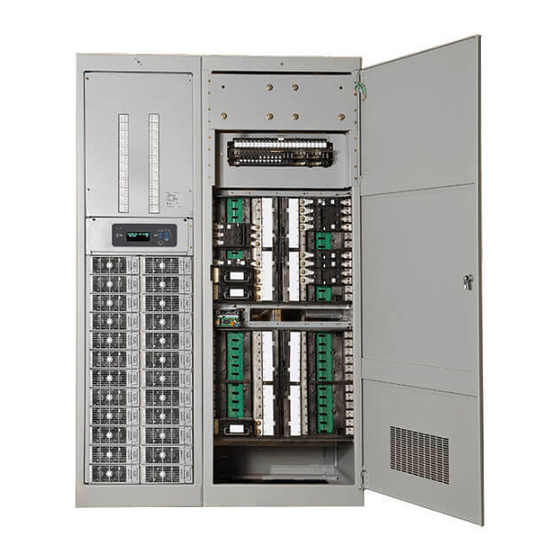
Chapter 1 Introduction 1.3.4 DC Distribution Cabinet The DC distribution cabinet is available in six models: PD48/1600DF-7-Y3, PD48/1600DF-7-Y4, PD48/1600DF-7/YF, PD48/2500DF-7-Y3, PD48/2500DF-7-Y4 and PD48/2500DF-7/YF. The appearances of the DC distribution cabinets are the same, as shown in Figure 1-9. Power distribution Power indicator Failure indicator Figure 1-9 Appearance of DC distribution cabinet... - Page 21 Chapter 1 Introduction The internal structure of DC distribution cabinet PD48/1600DF-7-Y3 is shown in Figure 1-10. Battery I fuse Battery II fuse Buzzer Buzzer control switch Fault silencer Controller LCD Control board Load fuse (a) Front view (open front door) DC positive busbar (b) Rear view (open front door and remove rear door) Figure 1-10...
- Page 22 Chapter 1 Introduction The internal structure of DC distribution cabinet PD48/1600DF-7-Y4 is shown in Figure 1-11. Battery I fuse Battery II fuse Buzzer Buzzer control switch Fault silencer Controller LCD Control board Load fuse (a) Front view (open front door) DC positive busbar (b) Rear view (open front door and remove rear door) Figure 1-11...
- Page 23 Chapter 1 Introduction The internal structure of DC distribution cabinet PD48/2500DF-7-Y3 is shown in Figure 1-12. Battery I fuse Battery II fuse Buzzer Buzzer control switch Fault silencer Controller LCD Control board Load fuse (a) Front view (open front door) DC positive busbar (b) Rear view (open front door and remove rear door) Figure 1-12...
- Page 24 Chapter 1 Introduction The internal structure of DC distribution cabinet PD48/2500DF-7-Y4 is shown in Figure 1-13. Battery I fuse Battery II fuse Buzzer Buzzer control switch Fault silencer Controller LCD Control board Load fuse (a) Front view (open front door) DC positive busbar (b) Rear view (open front door and remove rear door) Figure 1-13...
-
Page 25: Rectifier Cabinet
Chapter 1 Introduction The structure and configuration of PD48/1600DF-7/YFand PD48/2500DF-7/YF are determined by customer requirement. See purchase order for description. 1.3.5 Rectifier Cabinet Rectifier cabinets Rack 1000-7 and Rack 2000-7 are shown in Figure 1-14 and Figure 1-15 respectively. Figure 1-14 Rectifier cabinet Rack1000-7 NetSure 801 Series Power Supply System User Manual... - Page 26 Chapter 1 Introduction Rectifier input switch Controller Rectifier Figure 1-15 Rectifier cabinet Rack2000-7 The name, function and use of the cabinet components are given in Table 1-5. Table 1-5 Part name, function and use Name Function Cabinet When the mains input 1 is available, HL1 illuminates; when the mains AC cabinet, AC/DC cabinet input 2 is available, HL2 illuminates Power LED...
- Page 27 Chapter 1 Introduction Name Function Cabinet A6V6FA1 AC Sample the phase voltage of both mains inputs and the phase-B AC cabinet, AC/DC cabinet sampling board current of the running mains input Measure the AC input voltage, main switch state, output MCB state, surge protection device (SPD) state;...
-
Page 28: Chapter 2 Installation Preparation
Chapter 2 Installation Preparation Chapter 2 Installation Preparation This chapter introduces installation requirements, storage conditions, installation preparation and unpacking inspection. 2.1 Installation Requirements 2.1.1 Environmental Requirements The environmental conditions of the equipment room must meet the requirements listed in Table 2-1. Table 2-1 Environmental conditions for the equipment room Environmental conditions Recommended range... - Page 29 The equipment room should comply with relevant fire protection regulations and requirements for power distribution, and provide adequate fire protection facility, such as dry-chemical extinguisher and automatically explosive fire protection ball. NetSure 801 CA7 Power Supply System (New Skelecton) User Manual...
-
Page 30: Power Supply
Chapter 2 Installation Preparation 2.1.3 Power Supply General Mains power should be used as the main AC source in communication field; backup batteries and generator should be provided according to the actual power source conditions. AC source composed of mains power and user-provided generator should use centralized power supply mode to supply power, and low voltage AC power supply system should use three-phase five-line mode. -
Page 31: Equipment Running Environment Checklist
Lay antistatic floor or antistatic rubber Yes/No Weight capacity and quakeproof ability Accord with Level 8 quakeproof, and safety must be ensured Yes/No Radiation No blockage in equipment radiation passage Yes/No NetSure 801 CA7 Power Supply System (New Skelecton) User Manual... -
Page 32: Storage Conditions
No DC cabinet between AC cabinet and rectifier 04110145 W74AASL03 cable suite (AC input cable of the 3.5m cabinet. Internal cabling (≤ 2000A), When the AC (optional) rectifier cabinet-3.5m) output EMR1 series MCCB for Vertiv NetSure801 Series Power Supply System User Manual... - Page 33 1. The specs are applicable at ambient temperature of 25° C. If the temperature is higher or lower than this, the CSA of the cable should be increased. 2. The battery cable should reach at least +90° C heat durability. It is recommended to use double-insulated copper-core flame retardant cable as battery cable NetSure 801 CA7 Power Supply System (New Skelecton) User Manual...
-
Page 34: Unpacking Inspection
Chapter 2 Installation Preparation Table 2-6 DC load cable selection Load route rated Max. output Min. cable Max. cable length (volt drop: Max. cable length (volt drop: Max. cable CSA current current 0.5V, with min. CSA) 0.5V, with max. CSA) 630A 630A 240mm... - Page 35 5. The conditions of the goods through visual inspection. For example, check if the cabinet and case are damaged, if the cabinet and case have regained moisture; shake gently the rectifiers and controller to check if the parts and connections have been loosened during transportation. NetSure 801 CA7 Power Supply System (New Skelecton) User Manual...
-
Page 36: Chapter 3 Installation
Step 4: place cabinet in position Move the cabinet to the installation position aligning the installation holes of the cabinet with the reserve holes on the ground. NetSure 801 CA7 Power Supply System (New Skelecton) User Manual... -
Page 37: Installation On Supporting Rack
Install the supporting rack on the floor as shown in Figure 3-3. The installation steps are the same as the first three steps in 3.1.1 Installation On The Floor. Figure 3-3 Installing supporting rack NetSure 801 CA7 Power Supply System (New Skelecton) User Manual... -
Page 38: Parallel Connection Between Cabinets
× 30 bolt Make sure that the front door header of the rectifier cabinet aligns horizontally with that of the AC/DC cabinet during parallel connection. AC cabinet/DC cabinet Rectifier cabinet NetSure 801 CA7 Power Supply System (New Skelecton) User Manual... -
Page 39: Parallel Connection With Copper Bars
2. Connect the positive bars and negative bars inside the cabinet respectively by copper bars and screws, as shown in Figure 3-6. If users need to parallel connect the rectifier cabinets or the DC distribution cabinets, they need to contact Vertiv for technical support. -
Page 40: Installation Of System Above 2000A
3.1.5 Installation Of System Above 2000A The NetSure 801 CA7 power supply system can be expanded up to 6000A. As the max current carrying capacity of single parallel connection bar is 2000A, when the system capacity exceeds 2000A, the system cabinets should be arranged in the way that the max current carrying capacity of one parallel connection bar does not exceed 2000A. -
Page 41: Placing Dc Cabinet Separate From System
AC ATS cabinet) PD380/630AFA AC cabinet W64AASL06 cable suite (power cable of A6V6FU11 04116222 4.3m monitoring board) 04116169 W64AASL09 cable suite (CAN bus) 2.8m NetSure 801 CA7 Power Supply System (New Skelecton) User Manual... -
Page 42: Connecting Earth Cable
To earth terminal of rectifier rack To earth terminal of DC cabinet To earth copper bar of equipment room Bolt A amplication Spring washer Plain washer Figure 3-9 Earth bar of the AC distribution cabinet NetSure 801 CA7 Power Supply System (New Skelecton) User Manual... -
Page 43: Connecting Cables Between Rectifier Cabinet And Ac Distribution Cabinet
AC input cables. Otherwise users need to prepare armored cables by themselves. If the system capacity exceeds 2000A, users need to prepare extra cables. 2. Add cable lugs to both ends of the cables. NetSure 801 CA7 Power Supply System (New Skelecton) User Manual... - Page 44 Figure 3-11 Connection of AC input cables (phase line) of rectifier cabinet in AC distribution cabinet Neutral busbar Figure 3-12 Connection of AC input cables (neutral line) of rectifier cabinet in AC distribution cabinet NetSure 801 CA7 Power Supply System (New Skelecton) User Manual...
-
Page 45: Connecting Ac Input Cables
4. No splice, damage, or scratch on the cables is permitted. Connection The AC cables can enter the system from either the cabinet top from wiring rack or the cabinet bottom from cable trenching. For AC distribution cabinet: NetSure 801 CA7 Power Supply System (New Skelecton) User Manual... -
Page 46: Connecting Emergency Lighting Cables (Optional)
Connect one end of the negative emergency lighting cable to the bottom terminal of the emergency lighting MCB, and the other end to the negative terminal of the emergency lighting, as shown in Figure 3-17. NetSure 801 CA7 Power Supply System (New Skelecton) User Manual... -
Page 47: Connecting Dc Load Cables
The use of the top cover and the connection of DC load cables are the same with DC distribution cabinet. Taking the DC distribution cabinet as an example, the cable connection is described below. The use of the DC distribution cabinet top cover is described below: NetSure 801 CA7 Power Supply System (New Skelecton) User Manual... - Page 48 4. Connect one end of the negative cable to the output terminal of the fuse, and the other end of the positive cable to the positive copper bar of the DC distribution cabinet, as shown in Figure 3-19 and Figure 3-20. Figure 3-19 Connecting negative load cable NetSure 801 CA7 Power Supply System (New Skelecton) User Manual...
-
Page 49: Connecting Battery Cables
The battery negative cables should be connected to the two battery fuses, not the single one. Battery input cable Battery busbar (-) Bolt Plain washer Spring washer Cable connection finished Figure 3-21 Battery cable connection in DC cabinet NetSure 801 CA7 Power Supply System (New Skelecton) User Manual... -
Page 50: Installation Checklist
Figure 3-22 (b). 3. Tighten the bolts on the handle to fix the rectifier on the rack, as shown in Figure 3-22 (c) and Figure 3-22 (d). NetSure 801 CA7 Power Supply System (New Skelecton) User Manual... -
Page 51: Installing Controller
Fixing the controller on the slideway 2. Unscrew the captive screw at the top of the hand of the controller, as shown in Figure 3-24. Captive screw Handle Figure 3-24 Controller Panel diagram NetSure 801 CA7 Power Supply System (New Skelecton) User Manual... -
Page 52: The Installation And Wiring Of The Controller Ib2 Extension Board
Once the signal cable is connected, cover the IB2 extension board on the cover, and tighten the captive screws. Note The IB2 extension board should be installing in the rectifier cabinet with the controller when there are multiple rectifier cabinets in the system. NetSure 801 CA7 Power Supply System (New Skelecton) User Manual... - Page 53 DI7+ Digital input 7+ DI8- Digital input 8- DI8+ Digital input 8+ DO1_NC NC contact of relay 1 DO2_NC NC contact of relay 2 DO1_COM Common contact of relay 1 NetSure 801 CA7 Power Supply System (New Skelecton) User Manual...
-
Page 54: Connecting Communication Cables And Auxiliary Power Cable
1) Remove the matched resistance located on the back of rectifier cabinet, as shown in Figure 3-28. 匹配电阻 CAN communication cable Matched resistance CAN通信电缆 Figure 3-28 Matched resistance 2) Connect the CAN communication cables between the rectifier cabinets. NetSure 801 CA7 Power Supply System (New Skelecton) User Manual... - Page 55 Matching resistance attach the matching 监控 resistance 模块 here Rectifier Rectifier Rectifier cabinet 3 cabinet 2 cabinet 1 Figure 3-31 Rectifier cabinet CAN communication cable connection diagram 3 (rear view) NetSure 801 CA7 Power Supply System (New Skelecton) User Manual...
-
Page 56: Connecting Communication Cable Of Distribution Cabinet
3 PIN plug-in connectors connected RS485 cables of the PD380/630AFA AC distribution cabinet. In the RS485 port of the M831D controller, connect the RS485 communication cables from distribution cabinet through 3 PIN plug-in connectors. A处 A NetSure 801 CA7 Power Supply System (New Skelecton) User Manual... - Page 57 (black to black, brown to brown). Each AC cabinet corresponds to a DC cabinet, as shown in Figure 3-34. NetSure 801 CA7 Power Supply System (New Skelecton) User Manual...
-
Page 58: Installing Options
DC distribution cabinet (model: A6V6FU11), as shown in Figure 3-35. J4 has temperature compensation function. J5 and J6 perform temperature display function but not temperature compensation function. NetSure 801 CA7 Power Supply System (New Skelecton) User Manual... - Page 59 4. The temperature probe should be put in the battery room where it can best incarnate the battery temperature. When fixing it, do not connect it to any other exothermic equipment or metal conductor. NetSure 801 CA7 Power Supply System (New Skelecton) User Manual...
-
Page 60: Chapter 4 Testing
Preliminary test of controller After the controller is powered on, it will do self test without needing any operation. After about 50s, the M831D should start and display the following screen. NetSure 801 CA7 Power Supply System (New Skelecton) User Manual... -
Page 61: Setting Basic Parameters
Bits 1 to 5 are used to set the addresses of the AC distribution cabinets. Position ‘ON’ represents ‘0’, and ‘OFF’ represents ‘1’. The setting explanation of bits 1 to 5 is given in Figure 4-1 to Table 4-1. NetSure 801 CA7 Power Supply System (New Skelecton) User Manual... - Page 62 1 ~ 4 address Set it to ‘OFF’ during test Reserved Set it to ‘OFF’ during test Reserved Set it to ‘OFF’ during test Reserved Set it to ‘OFF’ during test Reserved NetSure 801 CA7 Power Supply System (New Skelecton) User Manual...
-
Page 63: Setting Basic Parameters For Controller
4-4 or there are two or above AC screens set to the same address, then reset the address according to 4.3.1 Setting DIP Switch. Model: LargeDU Software version: V1.08 Address: 72 Figure 4-4 DC screen address NetSure 801 CA7 Power Supply System (New Skelecton) User Manual... - Page 64 DC Distrib 1, and the current coefficient of battery string 3 and battery string 4 is the shunt coefficient of two battery ports in DC Distrib 2.) NetSure 801 CA7 Power Supply System (New Skelecton) User Manual...
- Page 65 Figure 4-9 Setting Temp Comp parameter LargeDU Large DUBatt1 2000 Large DUBatt2 2000 Figure 4-10 Setting Temp Number Note ‘DC Distrib 1’ corresponds to the DC distribution screen that with the lowest address. NetSure 801 CA7 Power Supply System (New Skelecton) User Manual...
-
Page 66: Checking Alarm And Operation Status
2. Set the system float/EQ voltage in the LCD of the controller according to 4.3.2 Setting Basic Parameters For Controller, the rectifier voltage should be normally adjustable. NetSure 801 CA7 Power Supply System (New Skelecton) User Manual... -
Page 67: Testing Dc Distribution
‘Settings’ ‘Maintenance’ screen, set the ‘Auto/Man State’ to ‘Auto’, as shown in Figure 4-15. Maintenance Auto/Man State: Auto EQ/FLT Control: Float Charge BattTestControl: Stop Rect Curr Limit: 121% Figure 4-15 Setting Auto/Man State NetSure 801 CA7 Power Supply System (New Skelecton) User Manual... -
Page 68: Access Controller Through Web
If the controller is connected to Internet and the user computer is connected to the intranet, the user cannot disable the proxy, otherwise you will have no access to the controller. NetSure 801 CA7 Power Supply System (New Skelecton) User Manual... - Page 69 4. Click on the Settings button. The following window opens, as shown in Figure 4-19. In the Settings window, choose “Every time I visit the webpage” and click OK. Figure 4-19 Temporary internet files and history settings NetSure 801 CA7 Power Supply System (New Skelecton) User Manual...
- Page 70 6. Click on Trusted sites. With “Trusted sites” selected, click “Sites”. The following window opens, as shown in Figure 4-21. Uncheck the “Require server verification (https:) for all sites in the zone:” box if https is not being used. Figure 4-21 Trusted sites NetSure 801 CA7 Power Supply System (New Skelecton) User Manual...
- Page 71 ENTER. The following Web Interface Login window opens, as shown in Figure 4-24. Enter a valid User Name and Password, and then click LOGIN. By default, the “User Name” is "admin" and the “Password” is “1”. NetSure 801 CA7 Power Supply System (New Skelecton) User Manual...
- Page 72 12. Control the boost/float and rectifier switch, check whether the control function is correct. 13. Simulate fault alarms on the power system, and then check whether corresponding alarms are displayed in the homepage. NetSure 801 CA7 Power Supply System (New Skelecton) User Manual...
-
Page 73: Chapter 5 Operation
When the LCD displays 3-phase line voltage, if the Ua voltage exists phase loss there will display phase loss at the back of Uab voltage; if the Ub voltage exists phase loss there will display phase loss at the back of Ubc voltage; NetSure 801 CA7 Power Supply System (New Skelecton) User Manual... - Page 74 53.5V Normal Normal Batt1 Fuse: On Indications of batteries are depended on the battery number set in the controller: two groups/one group or display any information about battery. NetSure 801 CA7 Power Supply System (New Skelecton) User Manual...
- Page 75 Figure 5-1 First system information screen 1. The first row displays the date and time alternately. 2. At the main menu screen, press the ESC key to return to the first system information screen. NetSure 801 CA7 Power Supply System (New Skelecton) User Manual...
- Page 76 There are two screens, as shown in Figure 5-4. MAIN MENU MAIN MENU Active Alarm Branch Info Branch Info History Alarm History Alarm Settings Figure 5-4 Main menu screen NetSure 801 CA7 Power Supply System (New Skelecton) User Manual...
- Page 77 2. Press ▲ or ▼ to view other history alarms. 3. At any history alarm screen, press the ESC key repeatedly to return to the higher-level menu, and ultimately return to the first system information screen. NetSure 801 CA7 Power Supply System (New Skelecton) User Manual...
- Page 78 1. At the Settings screen, press ▲ or ▼ to select the ‘Sys set’ menu. Then press the ENT key to confirm, as shown in Figure 5-10. Lang: English Tzone: GMT+08:00 Date: 2009-08-08 Time: 16:26:16 Figure 5-10 System settings NetSure 801 CA7 Power Supply System (New Skelecton) User Manual...
-
Page 79: Setting The Position Number Of The Rectifier Manually
Web control interface in the controller. 1. Refer to 4.4.3 Access Controller Through Web to enter the Web homepage window. NetSure 801 CA7 Power Supply System (New Skelecton) User Manual... - Page 80 Displayed on the Rectifier Device Group status page are the individual rectifiers installed in the system. 4. Click an individual rectifier icon to display its status such as "Current Limit", "Valid Rated Current", etc., as shown in Figure 5-13. NetSure 801 CA7 Power Supply System (New Skelecton) User Manual...
-
Page 81: Adding Load
Some rectifier guide rails are idle and covered with dummy plates when the power supply system is not fully configured. Before adding rectifier, these dummy plates must be removed so that new rectifiers can be mounted. NetSure 801 CA7 Power Supply System (New Skelecton) User Manual... - Page 82 The rated current of the rectifier input MCB is 20A, and its breaking capacity is 6kA. NetSure 801 CA7 Power Supply System (New Skelecton) User Manual...
-
Page 83: Chapter 6 Maintenance
Peel off the skin of cables, etc. Electrician rubber mallet 1 piece Rectify cables or equipment location Auxiliary materials (non-spare Commonly-used auxiliary materials include insulating tape, self-adhesive label, soldering tin, parts) nylon bandage, etc. NetSure 801 CA7 Power Supply System (New Skelecton) User Manual... -
Page 84: Reference Technical Specification For Maintenance
Microwave relay station, fiber relay station < 10 < 20 (may be up to 30 in the Microwave passive relay station case of high soil resistivity) NetSure 801 CA7 Power Supply System (New Skelecton) User Manual... -
Page 85: Routine Maintenance Items
NetSure 801 CA7 Power Supply System (New Skelecton) User Manual... - Page 86 70° C the temperature rise of the node. The measurement results should meet the temperature rise limitation and voltage drop limitation requirements NetSure 801 CA7 Power Supply System (New Skelecton) User Manual...
-
Page 87: Routine Maintenance
6.4 Basic Inspection 6.4.1 Handling Controller Fault When the faults of the controller affect the DC power supply, turn off the controller. NetSure 801 CA7 Power Supply System (New Skelecton) User Manual... -
Page 88: Handling Rectifier Fault
Remove the abnormal rectifier and Fault indicator on (red) Rectifier failure Overvoltage restart. Replace the rectifier if it occurs overvoltage again Fault indicator flashing Rectifier fan Fan fault Replace new fan (red) fault NetSure 801 CA7 Power Supply System (New Skelecton) User Manual... -
Page 89: Replacing Rectifier
4.Disconnect the rectifier switch, put the slide switch on position, grasp the handles, and push the rectifier into cabinet slowly, until it stops, as shown in Figure 6-3. Figure 6-3 Replacing rectifier (1) NetSure 801 CA7 Power Supply System (New Skelecton) User Manual... -
Page 90: Emergency Treatment
When this fault occurs, it shall be treated as follows: disconnect the AC power supply; isolate the batteries from the system; and then use batteries and rectifiers to directly supply power to load. NetSure 801 CA7 Power Supply System (New Skelecton) User Manual... - Page 91 Meanwhile, communication exchanges shall have adequate human and material resources and work out effective countermeasures to deal with these disasters. They shall also prepare emergency management regulations and grave accidents rush-repair rules. NetSure 801 CA7 Power Supply System (New Skelecton) User Manual...
-
Page 92: Appendix 1 Technical Parameter
DC output undervoltage protection Default: -45.0 ± 0.3Vdc, configurable through controller alarm point DC output undervoltage Default: -45.5 ± 0.3Vdc, 0.5Vdc lower than undervoltage alarm point alarm recovery point NetSure 801 CA7 Power Supply System (New Skelecton) User Manual... - Page 93 2000 (H) × 600 (W) × 600 (D) Mechnical Dimension (mm) Controller M831D 42 (H) × 86.6(W) × 211.5 (D) Rectifier R48-5800A, R48-5800e 88 (H) × 244 (W) × 372 (D) NetSure 801 CA7 Power Supply System (New Skelecton) User Manual...
- Page 94 Immunity to ESD Level 3 EN/IEC 61000-4-2 Immunity to EFT Level 4 EN/IEC 61000-4-4 Surge Level 4 EN/IEC 61000-4-5 Immunity to radiation Level 2 EN/IEC 61000-4-3 Immunity to conduction Level 2 EN/IEC61000-4-6 NetSure 801 CA7 Power Supply System (New Skelecton) User Manual...
- Page 95 Default 58Vdc, configurable through controller, 0.5Vdc hysteresis parameters Battery 1 undervoltage alarm point Default 58Vdc, configurable through controller, 0.5Vdc hysteresis Battery 1 overcurrent alarm point Default 100A, configurable through controller, 0.5A hysteresis NetSure 801 CA7 Power Supply System (New Skelecton) User Manual...
- Page 96 Dimension (mm) 2000 (H) × 800 (W) × 600 (D) PD48/1600DF-7-Y3 ≤ 280, PD48/1600DF-7-Y4 ≤ 280 Mechnical PD48/2500DF-7-Y3 ≤ 290, PD48/2500DF-7-Y4 ≤ 290 parameters Weight (kg) PD48/2500DF-7/YF, PD48/1600DF-7/YF ≤ 290 NetSure 801 CA7 Power Supply System (New Skelecton) User Manual...
-
Page 97: Appendix 2 Alarm List
Over Voltage 2 Critical Under Voltage 1 Critical Under Voltage 2 Critical DG Run OverTemp Observation DG1 is Running Observation DG1 is Running Observation DG1 Failure Observation DG1 Failure Observation NetSure 801 CA7 Power Supply System (New Skelecton) User Manual... - Page 98 The alarm happens during manual Battery Manual Test Observation battery test Group The alarm happens during planed battery Planned Test Observation test The alarm happens during AC power AC Fail Test Observation failure test NetSure 801 CA7 Power Supply System (New Skelecton) User Manual...
- Page 99 M2 Ubc/Ub OverV Observation Relay 2 M2 Uca/Uc OverV Observation Relay 2 M3 Uab/Ua OverV Observation Relay 2 M3 Ubc/Ub OverV Observation Relay 2 M3 Uca/Uc OverV Observation Relay 2 NetSure 801 CA7 Power Supply System (New Skelecton) User Manual...
- Page 100 Major Relay 3 T2 Under Temp Major Relay 3 T3 Under Temp Major Relay 3 T1 Sensor Fail Observation None T2 Sensor Fail Observation None T3 Sensor Fail Observation None NetSure 801 CA7 Power Supply System (New Skelecton) User Manual...
-
Page 101: Appendix 3 Terminologies
For every 1° C increase (or decrease) of battery string temperature, the decrease (or increase) of float compensation charging voltage, and the unit is mV/(° C· per battery string). This parameter should be set according to the coefficient actual temperature compensation requirement of battery NetSure 801 CA7 Power Supply System (New Skelecton) User Manual... - Page 102 A kind of battery test method, in this test method, M831D controls the output voltage of the rectifier to Full load test make the battery take all the loads NetSure 801 CA7 Power Supply System (New Skelecton) User Manual...
-
Page 103: Appendix 4 Engineering Design Diagram
Appendix 4 Engineering Design Diagram Engineering design diagram for AC distribution cabinet 654.0 880.0 912.0 1036.0 1134.8 2000.0 206.2 387.5 800.0 Figure 1 PD380/630AFH-7-Y3 engineering design diagram (front view, unit mm) NetSure 801 CA7 Power Supply System (New Skelecton) User Manual... - Page 104 Appendix 4 Engineering Design Diagram 2000 Figure 2 PD380/630AFH-7-Y3 engineering design diagram (rear view, unit: mm) NetSure 801 CA7 Power Supply System (New Skelecton) User Manual...
- Page 105 Appendix 4 Engineering Design Diagram 654.0 880.0 912.0 1036.0 1134.8 2000.0 206.2 387.5 800.0 Figure 3 PD380/400AFH-7-Y2 engineering design diagram (front view, unit: mm) NetSure 801 CA7 Power Supply System (New Skelecton) User Manual...
- Page 106 Appendix 4 Engineering Design Diagram 2000 Figure 4 PD380/400AFH-7-Y2 engineering design diagram (rear view, unit: mm) NetSure 801 CA7 Power Supply System (New Skelecton) User Manual...
- Page 107 926.7 2000 107.5 174.8 584.5 625.5 Figure 5 PD380/630AFA-7-Y4 engineering design diagram (front view, unit: mm) 979.5 2000 217.2 547.5 Figure 6 PD380/630AFA-7-Y4 engineering design diagram (rear view, unit: mm) NetSure 801 CA7 Power Supply System (New Skelecton) User Manual...
- Page 108 Engineering design diagram for DC distribution cabinet 115.5 120.6 227.5 270.0 99.5 648.5 694.0 1088.5 2000.0 40.0 40.0 153.5 800.0 Figure 7 PD48/1600DF-7-Y3 engineering design diagram (front view, unit: mm) NetSure 801 CA7 Power Supply System (New Skelecton) User Manual...
- Page 109 Appendix 4 Engineering Design Diagram 93.1 437.0 2000.0 Figure 8 PD48/1600DF-7-Y3 engineering design diagram (rear view, unit: mm) NetSure 801 CA7 Power Supply System (New Skelecton) User Manual...
- Page 110 Appendix 4 Engineering Design Diagram 120.6 115.5 270.0 227.5 99.5 652.5 694.0 1235.0 2000.0 800.0 Figure 9 PD48/1600DF-7-Y4 engineering design diagram (front view, unit: mm) NetSure 801 CA7 Power Supply System (New Skelecton) User Manual...
- Page 111 Appendix 4 Engineering Design Diagram 93.1 437.0 2000.0 Figure 10 PD48/1600DF-7-Y4 engineering design diagram (rear view, unit: mm) NetSure 801 CA7 Power Supply System (New Skelecton) User Manual...
- Page 112 270.0 99.5 652.5 694.0 1235.0 2000.0 800.0 Figure 11 PD48/2500DF-7-Y3 engineering design diagram (front view, unit: mm) 92.1 437.0 2000.0 Figure 12 PD48/2500DF-7-Y3 engineering design diagram (rear view, unit: mm) NetSure 801 CA7 Power Supply System (New Skelecton) User Manual...
- Page 113 227.5 99.5 652.5 694.0 1235.0 2000.0 800.0 Figure 13 PD48/2500DF-7-Y4 engineering design diagram (front view, unit: mm) 93.1 437.0 2000.0 Figure 14 PD48/2500DF-7-Y4 engineering design diagram (rear view, unit: mm) NetSure 801 CA7 Power Supply System (New Skelecton) User Manual...
- Page 114 Appendix 4 Engineering Design Diagram The engineering design diagrams PD48/1600DF-7/YF and PD48/2500DF-7/YF varies according to practical configuration. Engineering design diagram for rectifier cabinet Figure 15 Rack2000-7 engineering design diagram (front view, unit: mm) NetSure 801 CA7 Power Supply System (New Skelecton) User Manual...
- Page 115 Appendix 4 Engineering Design Diagram Figure 16 Rack2000-7 engineering design diagram (rear view, unit: mm) NetSure 801 CA7 Power Supply System (New Skelecton) User Manual...
- Page 116 Appendix 4 Engineering Design Diagram 67.9 67.9 30.5 30.5 121.7 121.7 2000 2000 Figure 17 Rack1000-7 engineering design diagram (front view, unit: mm) NetSure 801 CA7 Power Supply System (New Skelecton) User Manual...
- Page 117 Appendix 4 Engineering Design Diagram 309.8 309.8 1156.6 1156.6 Figure 18 Rack1000-7 engineering design diagram (rear view, unit: mm) NetSure 801 CA7 Power Supply System (New Skelecton) User Manual...
-
Page 118: Appendix 5 Spare Part List
Finished Board-A6V6FU11-A6V6FZB1-Monitoring Board-ROHS PD48/2500DF-7-Y3 PD48/2500DF-7-Y4 Manufactured board - A2V6FZ - A2V6FX1 - PD380/630AFH-2 AC/DC signal transfer 03023191 DC distribution cabinet board 03025735 Manufactured board - W442FZ-SPD13D - power supply DC PS board NetSure 801 CA7 Power Supply System (New Skelecton) User Manual... -
Page 119: Appendix 6 Wiring Diagram
RECT.7 排 10-2 10-4 10-6 CAN+ CAN- PE CAN+ CAN- RECT.10 RECT.9 Module socket rear enlarge picture CAN+ CAN- CAN+ CAN- -48V Figure 19 Rack1000-7 rectifier cabinet wiring diagram 1 NetSure 801 CA7 Power Supply System (New Skelecton) User Manual... - Page 120 2 4 6 2 4 6 Three-phase bus bar QF10 2 4 6 2 4 6 2 4 6 2 4 6 2 4 6 Figure 20 Rack1000-7 rectifier cabinet wiring diagram 2 NetSure 801 CA7 Power Supply System User Manual...
- Page 121 20-6 19-6 CAN+ CAN- PE CAN+ CAN- RECT.20 RECT.19 -48V -48V Module socket (rear view enlarge picture) CAN+ CAN- CAN+ CAN- -48V Figure 21 Rack2000-7 rectifier cabinet wiring diagram 1 NetSure 801 CA7 Power Supply System (New Skelecton) User Manual...
- Page 122 2 4 6 2 4 6 2 4 6 2 4 6 2 4 6 2 4 6 2 4 6 2 4 6 Figure 22 Rack2000-7 rectifier cabinet wiring diagram 2 NetSure 801 CA7 Power Supply System User Manual...
- Page 123 31-J2-7 33-J4-5 23-1 -48V 33-J4-4 33-J4-8 26-3 33-J4-3 8 31-J1-6 33-J4-2 27-1 31-J1-5 33-J4-1 31-J1-4 31-J1-3 31-J1-2 31-J1-1 31-J0-2 31-J0-1 A2V6FX1 38-4 38-2 A2V4FA1 Figure 23 PD380/400AFH-7-Y2 wiring diagram (1) NetSure 801 CA7 Power Supply System (New Skelecton) User Manual...
- Page 124 38-1 1 QF10 38-3 2 39-2 39-4 39-6 Three-phase bus bar B12 B14 B12 B14 QF11 QF12 PE bar 39-8 QF10 QF10 41-PE QF11 QF12 QF11 QF12 Figure 24 PD380/400AFH-7-Y2 wiring diagram (2) NetSure 801 CA7 Power Supply System User Manual...
- Page 125 Cabinet 33-J4-5 23-1 -48V 33-J4-4 33-J4-8 26-3 33-J4-3 8 31-J1-6 33-J4-2 27-1 31-J1-5 33-J4-1 31-J1-4 31-J1-3 31-J1-2 31-J1-1 31-J0-2 31-J0-1 A2V6FX1 38-4 38-2 A2V4FA1 Figure 25 PD380/630AFH-7-Y3 wiring diagram (1) NetSure 801 CA7 Power Supply System (New Skelecton) User Manual...
- Page 126 QF10 38-1 38-3 39-2 39-4 39-6 Three-polarity busbar QF11 QF12 N bar 39-8 PE bar 41-PE QF10 QF13 QF10 QF11 QF12 QF11 QF12 QF13 QF14 QF13 Figure 26 PD380/630AFH-7-Y3 wiring diagram (2) NetSure 801 CA7 Power Supply System User Manual...
- Page 127 PGND DGND RS485- RS485+ GEN-NO GEN-COMGEN-NC ALM-COM ALM-NO Note: 1. Discard the ATS cable (LTSC2000SLW03)if it is unnecessary. 2.Discard ATS cable(230S400SLW01-X1) if it is unnecessary. Figure 27 PD380/630AFA-7-Y4 wiring diagram 1 NetSure 801 CA7 Power Supply System (New Skelecton) User Manual...
- Page 128 QF1 QF3 QF4 QF15 QF16 AC output 2~6 QF10 QF17 QF18 QF19 QF20 MCB three-phase busbar ( ) AC output 7 PE bar N bar NBUS Figure 28 PD380/630AFA-7-Y4 wiring diagram 2 NetSure 801 CA7 Power Supply System User Manual...
- Page 129 4. If the entry cable is more than one group, make sure that the output MCB quantity of each entry cable is equal. 2 3 1 3 1 2 1 2 3 Figure 29 PD380/630AFA-7-Y4 wiring diagram 3 NetSure 801 CA7 Power Supply System (New Skelecton) User Manual...
- Page 130 7-J2-8 13-4 7-J1-6 13-3 7-J2-7 7-J1-5 7-J2-6 13-2 7-J1-4 7-J2-5 13-1 7-J1-3 7-J2-4 7-J1-2 The total load current 7-J2-3 Hall signals 7-J1-1 7-J2-2 7-J0-2 7-J2-1 7-J0-1 A2V6FX1 Figure 30 PD48/2500DF-7-Y3 wiring diagram NetSure 801 CA7 Power Supply System User Manual...
- Page 131 Connect to the signal transfer board Connect to the signal transfer board JP 2 JP 1 Door Cabinet Earthing wire (four) The total load current Hall signals Figure 31 PD48/2500DF-7-Y4 wiring diagram NetSure 801 CA7 Power Supply System (New Skelecton) User Manual...
- Page 132 7-J2-8 13-4 7-J1-6 7-J2-7 7-J1-5 13-3 7-J2-6 7-J1-4 13-2 7-J2-5 7-J1-3 13-1 7-J2-4 7-J1-2 7-J2-3 The total load current 7-J1-1 7-J2-2 7-J0-2 Hall signals 7-J2-1 7-J0-1 A2V6FX1 Figure 32 PD48/1600DF-7-Y3 wiring diagram NetSure 801 CA7 Power Supply System User Manual...
- Page 133 Earthing wire (four) 13-3 7-J1-5 7-J2-6 7-J1-4 13-2 7-J2-5 7-J1-3 13-1 7-J2-4 7-J1-2 7-J2-3 The total load current 7-J1-1 7-J2-2 7-J0-2 Hall signals 7-J2-1 7-J0-1 A2V6FX1 Figure 33 PD48/1600DF-7-Y4 wiring diagram NetSure 801 CA7 Power Supply System (New Skelecton) User Manual...
Need help?
Do you have a question about the NetSure 801 CA7 and is the answer not in the manual?
Questions and answers