
Subscribe to Our Youtube Channel
Related Manuals for Munters Platinum Touch


Summary of Contents for Munters Platinum Touch
- Page 1 Platinum Touch / User Manual Rotem One Touch Platinum Touch/Rotem One Touch Ag/MIS/UMGB-2444-03/17 Rev 1.0 P/N: 11756...
- Page 2 Platinum Touch/Rotem One Touch User Manual Revision: N.1.0 of 03.2019 Ag/MIS/UMGB-2444-03/17 Rev 1.7 (MIS) Product Software: 7.18/8.18 This manual for use and maintenance is an integral part of the apparatus together with the attached technical documentation. This document is destined for the user of the apparatus: it may not be reproduced in whole or in part, committed to computer memory as a file or delivered to third parties without the prior authorization of the assembler of the system.
- Page 3 INTRODUCTION ------------------------------------------------------------------------------------------------------------------------------------------ 8 1.1 Disclaimer -------------------------------------------------------------------------------------------------------------------------------------------------------------------------------- 1.2 Introduction ----------------------------------------------------------------------------------------------------------------------------------------------------------------------------- 1.3 Notes ----------------------------------------------------------------------------------------------------------------------------------------------------------------------------------------- INTRODUCTION TO THE PLATINUM TOUCH/ROTEM ONE TOUCH ------------------------------------- 9 2.1 Main Screen -------------------------------------------------------------------------------------------------------------------------------------------------------------------------- 2.2 Menu Elements ------------------------------------------------------------------------------------------------------------------------------------------------------------------ 2.3 Version ----------------------------------------------------------------------------------------------------------------------------------------------------------------------------------- 2.4 Software Upgrade ---------------------------------------------------------------------------------------------------------------------------------------------------------- 2.5 Rotem One LEDs --------------------------------------------------------------------------------------------------------------------------------------------------------------- 2.6 Selecting the Mode...
-
Page 4: Table Of Contents
Alarm Setting Help | Set Definitions ..................4.4.2 Prioritizing Alarms ........................4.5 Alarm Reset ------------------------------------------------------------------------------------------------------------------------------------------------------------------------- 4.6 Fail Safe Settings -------------------------------------------------------------------------------------------------------------------------------------------------------------- 4.7 Password ------------------------------------------------------------------------------------------------------------------------------------------------------------------------------- 4.8 Feeders & Drinkers ---------------------------------------------------------------------------------------------------------------------------------------------------------- 4.8.1 Feeders & Drinkers Help | Set Definitions ................© Munters AB, 2018... - Page 5 Vent & Curtain Levels ........................6.5.4 Variable Speed Fan Levels ....................... 6.5.5 Stir and Variable Fan Levels ..................... 6.6 Stir Fan Program --------------------------------------------------------------------------------------------------------------------------------------------------------------- 6.6.1 Stir Fan Program Help | Set Definitions ................6.7 Relay Layout ----------------------------------------------------------------------------------------------------------------------------------------------------------------------- © Munters AB, 2018...
- Page 6 CO2 Sensor Calibration ......................8.1.4 Static Pressure Calibration ..................... 8.1.5 Light Sensor Calibration ......................8.1.6 Feed Calibration ........................8.1.7 Water Calibration ........................8.1.8 Ventilation Potentiometer Calibration ................8.1.9 Nipple Flushing .......................... 8.1.10 Feeders & Drinkers ........................© Munters AB, 2018...
- Page 7 10.6 Work Room Control --------------------------------------------------------------------------------------------------------------------------------------------------- 10.7 Scale Arm ------------------------------------------------------------------------------------------------------------------------------------------------------------------------- 10.8 Breeder Advanced Feeding ----------------------------------------------------------------------------------------------------------------------------------- 10.8.1 Selecting the Mode ........................10.8.2 Setup .............................. 10.8.3 Feed Scale Program Help | Set Definitions ..............10.9 Egg Room History -------------------------------------------------------------------------------------------------------------------------------------------------------- WARRANTY ----------------------------------------------------------------------------------------------------------------------------------------------- 149 © Munters AB, 2018...
- Page 8 The information contained herein has been prepared by qualified experts within Munters. While we believe the information is accurate and complete, we make no warranty or representation for any particular purposes. The information is offered in good faith and with the understanding that any use of the units or accessories in breach of the directions and warnings in this document is at the sole discretion and risk of the user.
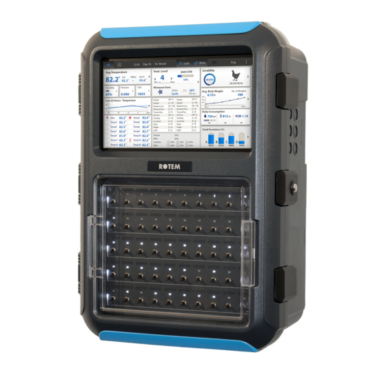
- Page 9 (even one); they are white when there are no alarms. Refer to the main screen to view the alarms. Selecting the Mode • 2.1 Main Screen Figure 1 shows the Platinum Touch/Rotem One Touch Main Screen. Figure 1: Platinum Touch/Rotem One Touch Main Screen © Munters AB, 2018...
- Page 10 Displays the house status (full house or brood mode) defined in the Click this button to prevent any user from making changes to the parameters. Click to turn off alarms. However, Platinum Touch/Rotem One Touch continues to register alarms until alarms are reset.
- Page 11 Software Upgrade You can upgrade certain software programs from the Web application. Platinum Touch/Rotem One Touch software • Web application • Comm-Box software • NOTE You cannot upgrade product software! Upgrade your product software using the procedures given in the product manuals.
- Page 12 (even one); they are white when there are no alarms. Refer to the main screen to view the alarms. 2.6 Selecting the Mode Platinum Touch/Rotem One Touch runs in four modes: Broiler, Layer, Breeders, and Pigs. To select the mode: 1. Open the door. Locate the keyboard.
- Page 13 System Parameters • Ammonia Treatment • Feed Scale Program • Light Dimmers • NOTE If an RLED 2.0 is connected to the Platinum Touch/Rotem One Touch, the menu includes “Light Dimmers”. Refer to Light Dimmers, page 56. © Munters AB, 2018...
- Page 14 This screen sets the temperature targets according to the bird age. 1. In System > Sensors > Analog, designate the required number of sensors as temperature sensors. When using more than one sensor, Platinum Touch/Rotem One Touch begins treatments based on the average.
- Page 15 Platinum Touch/Rotem One Touch reminds you. When you press Enter to acknowledge the reminder, the Platinum Touch/Rotem One Touch logs it in the Table of Events. o Target Temperature Band: The size of the target temperature zone. This "Happy Zone”...
- Page 16 If the temperature continues to drop, heaters operate for longer periods of time, up to the • Maximum On Time (defined in Levels of Ventilation). Platinum Touch/Rotem One Touch automatically generates a curve. • In this example: Temperature Curve Heat Off is 78°.
- Page 17 Radiant High – Differential (Below Low Set): Set number of degrees below Radiant Low Heaters for HIGH Radiant Heaters to begin working (default: 1.0). To ensure proper heater ignition, Radiant High Heaters remain on for the Radiant Ignition Time along with the Radiant Low Heaters. © Munters AB, 2018...
- Page 18 3.1.4 V ARIABLE EATER EFINITIONS The Platinum Touch/Rotem One Touch enables configuring up to eight variable heaters. The output of the heaters changes as the temperature increases or decreases. Install at least one analog output card. To configure the variable heaters: 1.
- Page 19 High Difference Below Heat: Temperature at which the heater begins to operate at maximum output. 3.1.4.2 Proportional Heat Proportional Heat works in manner similar to Linear Mode. The difference is that Proportional Heat features a delay time. © Munters AB, 2018...
- Page 20 After the response time passes, Platinum Touch/Rotem One Touch checks the temperature. If it • is still below the defined point, Platinum Touch/Rotem One Touch increases the voltage by a certain amount (this amount of the increase cannot be changed).
- Page 21 Once you have entered the ventilation levels, use the Min/Max to select the range of levels to apply to your situation. Typically, Platinum Touch/Rotem One Touch increases the minimum ventilation level as litter conditions deteriorate and the birds require greater amounts of fresh air. You can also restrict the maximum level to prevent excess airflow on young birds.
- Page 22 From: Set time of day (hh:mm) in 24 hour format. o Minimum Level: Set minimum ventilation level for controller. o Maximum Level: Set maximum ventilation level for controller. 3.2.3 S 1. Define: o Day: Set the growth day. © Munters AB, 2018...
- Page 23 The By Weight option enables controlling the minimum air flow depending on the number of birds, their weight and the current outside temperature. When using the Weight option, Platinum Touch/Rotem One Touch takes several parameters and calculates the air speed, level of ventilation and cycle time needed to supply the required volume.
- Page 24 Kg/Lb rises to 0.65; on Day 8, 0.8 and so on. Maximum Level: Set the maximum level of ventilation. • 8. If required, click and set the parameters. 9. In Management > Inventory, type the number of birds. © Munters AB, 2018...
- Page 25 Minimum ON Time in Vent Cycle: The minimum amount of time that the fans operate during a ventilation cycle. Platinum Touch/Rotem One Touch adjusts the actual fan time as needed. o Minimum OFF Time in Vent Cycle: The minimum amount of time that the fans do not operate during a ventilation cycle.
- Page 26 3.3 Introduction to Humidity, Ammonia, and CO2 Treatment Platinum Touch/Rotem One Touch provides various options to controlling the humidity, CO2, and ammonia levels. None: No treatment is provided.
- Page 27 1. In System > Sensors > Analog, designate one or two sensors as indoor humidity sensors (outdoor sensor is for information only). When using more than one sensor, Platinum Touch/Rotem One Touch begins treatments based on the average. 2. In Control > Humidity Treatment define: o Day: Set the growth day.
- Page 28 Day: Growth day. You can set multiple programs for same day (maximum number of programs: 20) o Start Value: CO2 value at which to begin treatment o Stop Value: CO2 value at which to end treatment o Delay: Number of seconds the controller pauses before ventilating © Munters AB, 2018...
- Page 29 This number can be positive or negative. CO2 Treatment by Heater requires designating at least one thermometer as an outside thermometer (refer to Temperature Definition, page 99). © Munters AB, 2018...
- Page 30 3.6.1 H ATURAL ENTILATION For Platinum Touch/Rotem One Touch to switch to Natural Ventilation: Natural Ventilation works only during the defined growth days and daily schedule. • The temperature inside the chicken house must be within the inside temperature band.
- Page 31 Winds that come within this area (A) are used for Natural Programing. The controller disregards winds outside of this area (B & C). 4. If required, in System > Temperature Definition designate a temperature sensor as an outside sensor. © Munters AB, 2018...
- Page 32 Minimum Wind Speed for Tunnel Temperature: When the unit is in Natural Mode, if the temperature rises above the Tunnel Temperature, Platinum Touch/Rotem One Touch switches to Tunnel mode unless the wind speed is above the speed set here.
- Page 33 Minimum Curtain Position: Set the minimum curtain open position. o Maximum Curtain Position: Set the maximum curtain open position. o Wind and Rain Effect: Enables Platinum Touch/Rotem One Touch to consider additional parameters (found in the Help) when calculating the maximal curtain opening.
-
Page 34: Natural Programming Help | Set Definitions
Low Wind Speed With Rain: If there is a rain detector, curtains open completely when there is rain. o High Wind Speed With Rain: If there is a rain detector, curtains close completely when there is rain. NOTE Between these levels, the controller opens the curtain based on a curve. © Munters AB, 2018... -
Page 35: What Happens When The Controller Transitions
Tunnel Ventilation Static Pressure • 3.7.1.1 Attic Static Pressure Define: • o Target Static Pressure: Set the required static pressure when in attic mode. o Static Pressure Band: Set the required band for attic ventilation mode. © Munters AB, 2018... - Page 36 Low Static Pressure Alarm: Set alarm for low static pressure. If you disable it by setting zero, the Platinum Touch/Rotem One Touch warns you and enters a record in the Table of Events.
-
Page 37: Disabling The Static Pressure Sensor
Low Static Pressure Alarm Minimum Level Low S.P. Alarm Min. Level (Tun.): Below this level, the controller ignores low static pressure alarms while in tunnel mode. © Munters AB, 2018... -
Page 38: Multi Stage Tunnel Curtains
UNNEL URTAINS When in static pressure mode and employing multiple tunnel curtains, Platinum Touch/Rotem One Touch can open the curtains in sequence. Opening the tunnel curtains commences when the target static pressure is reached and the controller signals to the tunnel machine to operate the curtains. Platinum Touch/Rotem One Touch opens the first tunnel curtain (as defined in the relays) to the user defined level. -
Page 39: Cool Pad Help | Set Definitions
Temperature Band: Define the on/off delay relative to temperature. o Humidity Band (%): Define the on/off delay relative to humidity. o Diff Between Cool Pads Stage: Platinum Touch/Rotem One Touch supports four cooling pad stages. The controller activates the first stage when the temperature reaches the Tunnel Temperature (Control >... -
Page 40: Foggers
On Sec: Set the maximum on time for each cycle of fogger operation. • Off Sec: Set the minimum off time for each cycle of fogger operation. • 3. If required, click and parameters as required. 3.9.1 F OGGERS EFINITIONS © Munters AB, 2018... -
Page 41: Water & Feed Control
NOTE Munters recommends keeping this function set at the default setting (No). o Difference between Foggers Stage: Platinum Touch/Rotem One Touch supports four fogging stages. The controller activates the first stage when the temperature reaches the Target Temperature (Control > Temperature Curve) plus the foggers differential. Each additional stage begins when the temperature reaches the Target Temperature plus the fogger differentiation. -
Page 42: Control Via Quantity
1. In System > Relay Layout, define relays as Water, Feed, or Auger. 2. In System > Scale Layout, map each silo to a channel. 3. Go to Control > Water & Feed > Set. 4. Go to Control > Water & Feed. © Munters AB, 2018... - Page 43 This function only works when relays are defined as augers and each silo is mapped to an auger. Defining a digital sensor as a feed count does not enable Control by Quantity. NOTE If both Control via Quantity and a digital feed counter are enabled, Control via Quantity takes priority. © Munters AB, 2018...
-
Page 44: Water And Feed Help | Set Definitions
Week/Days Cycle (2 – 6 Days): Select which days in the cycle that feed and water is delivered. o Water on No Feed Days: Select up to two time periods when water is delivered on non- feed days. NOTE On feed days, water is delivered when feed is delivered. © Munters AB, 2018... -
Page 45: Light
Light Dimmer (%): Set intensity in percentage for light dimmer(s). Dimmer lights start to brighten • if the intensity increases, and complete dimming if the intensity decreases at the set time. That is, they start dimming the ‘sunset time’ in advance of the set time (see Help | Set below). © Munters AB, 2018... -
Page 46: Light Help | Set Definitions
Light Sensor Active: The light sensor turns off all lights when sufficient outside lights exists. If a light sensor is installed, enable this option to turn off the light during feeding time when there is sufficient outside light. Refer to Light Sensor Calibration for details. © Munters AB, 2018... -
Page 47: Extra Systems
Humidity From: Humidity above which Extra System operates • Humidity To: Humidity below which Extra System operates. • On (Sec): On time for the Extra System. If set to 0, the extra system does not operate. • © Munters AB, 2018... -
Page 48: Control Mode
Heat Cycle: Enable cycle heaters. Refer to Cycle Heaters Help | Set Definitions, page o Analog Heat Mode: Define the variable heating mode (Linear, Proportional, Linear Valve). Refer to Variable Heater Help | Set Definitions, page 18. © Munters AB, 2018... -
Page 49: System Parameters
Day: Growth day. You can set multiple programs for same day (maximum number of programs: 20) o Start Value: Ammonia value at which to begin treatment. Range: 0 to 100. Default: 2 NOTE Ammonia levels should not be higher than 30 ppm. © Munters AB, 2018... -
Page 50: Ammonia Treatment Help | Set Definitions
• 1. In System > Relay Layout (page 94), define relays as augers as required. 2. In Management > Bird Inventory (page 58), enter the number of birds. 3. Go to Control > Feed Scale Program. © Munters AB, 2018... -
Page 51: Feed Scale Help | Set Definitions
4. Define: o Day: Define the days at which the feed per bird changes. Platinum Touch/Rotem One Touch calculates a feed curve based on these days. You can define the days as negative days. o Feed per Bird: Define the amount of feed per bird/pigs (kilograms) to be distributed. -
Page 52: Feed Scale Hot Screen
There are three settings; Default, Slower, Faster. NOTE Munters recommends leaving this parameter at the default level. o Valve Close Time [seconds]: Set the delay in time, if any, that the valve emptying the feed scale closes. -
Page 53: Feed Scale Functionality In Two Houses
OUSES Platinum Touch/Rotem One Touch enables sharing feed scale functionality between two houses. Two load cells are connected to a single feed scale. Each Platinum Touch/Rotem One Touch Controller is connected to one load cell. When the system is running, one controller operates each set of augers, feed scale valve, hoppers, and so on. - Page 54 Figure 7: Feed scale block diagram © Munters AB, 2018...
- Page 55 1. Go to System > Relay Layout. 2. Define a relay as Feed S. Active. 3. Go to System > Digital Sensor. 4. Define one sensor as Hopper Sensor and one sensor as Feed Scale Interlock. © Munters AB, 2018...
-
Page 56: Light Dimmers
3.17 Light Dimmers Platinum Touch/Rotem One Touch supports configuring up to five RLED 2.0 Light Dimmers from the Platinum Touch/Rotem One Touch screen. RLED 2.0 can be connected via a Platinum Touch/Rotem One Touch communication card or via an analog output card. Each RLED 2.0 has two independent channels;... - Page 57 You can map the channels to the light lines in any order. 4. Go to Control > Light. 5. Define the parameters as described Light, page 45. 6. The main screen now displays the active and inactive light lines. © Munters AB, 2018...
-
Page 58: Management Menu
• Alarm Reset • Fail Safe Settings • Password • Feeders & Drinkers • Nipple Flushing • Water on Demand • Current Sense • 4.1 Bird Inventory Maintain your inventory by entering data into the controller. © Munters AB, 2018... -
Page 59: Feed Inventory
Feed Alarms. If you have installed load cells and connected silo scales to your Platinum Touch/Rotem One Touch, it automatically maintains feed inventory, including delivery dates and feed consumption data. You can monitor your fill system and maintain approximate feed inventory using the Digital Inputs. -
Page 60: Feed Inventory Help | Set Definitions
New Flock: Use the new flock function on arrival of a new set of birds to set the growth day back to 1, 0, -1, or -2, and to clear out old history data. © Munters AB, 2018... -
Page 61: Alarm Settings
Control > Temperature Curve >Low Alarm Temperature. Alarms o Alarm Test at Time (hh:mm): Schedule the alarm test time. o Day of Alarm Test: Choose Daily or a particular day of the week for the scheduled alarm. © Munters AB, 2018... - Page 62 Auger Overtime Delay (minute): Set the maximum auger run time for your cross fill system. If you have a monitor connected to the digital inputs programmed as Feeder-1 Overtime or Feeder-2 Overtime the Platinum Touch/Rotem One Touch sends an alarm after this delay.
-
Page 63: Alarm Setting Help | Set Definitions
You can define a first day at which to start increasing the overflow limit automatically. Days prior to the ‘First Day’ use the First Day overflow limit; days following the first day have an incremental curve toward the LAST DAY OVERFLOW parameter setting. © Munters AB, 2018... - Page 64 CO2 High Level: Set the maximum allowed CO2 level above which an alarm is sent. The alarm ceases when the CO2 drops below this level. If the user acknowledges the alarm, the alarm messages temporarily cease (for the reminder time). © Munters AB, 2018...
-
Page 65: Prioritizing Alarms
0:00 (default) the alarm is disabled. 4.4.2 P RIORITIZING LARMS Platinum Touch/Rotem One Touch enables prioritizing alarms. When enabled: ventilation-related alarms are defined as critical. The main alarm relay will transmit these • alarms to the device wired to the relay (for example, a dialer). -
Page 66: Alarm Reset
4.6 Fail Safe Settings When there is a problem such as extremely high air temperature, the Fail-Safe function immediately activates a backup system (for example the FBU-27 ) to ensure that adequate ventilation continues. © Munters AB, 2018... -
Page 67: Password
The Platinum Touch/Rotem One Touch has six options besides controller failure or power off to activate the fail-safe relay. High/Low Temperature: Select to trigger fail-safe when the temperature is exceptionally • high/low. Low/High Static Pressure: Select to trigger fail-safe when the static pressure is exceptionally •... -
Page 68: Feeders & Drinkers Help | Set Definitions
Water line 1 through 122 Water line 10: Individual water line supplementary to select the line to flush During normal operation, only relay 111 water main is active. During a flushing relay, code 112 is active together with each individual water line relays, each one running in turn. © Munters AB, 2018... -
Page 69: Scheduling The Flush
(manual or solenoid according to the mode installed). Platinum Touch/Rotem One Touches enables controlling the water cycle times using relays and controlling the water pressure using analog input and output sensors. The two methods are complimentary. A user can use either one alone or both. -
Page 70: Relay Control
Specify up to 50 time periods. o Relays: Enable the required relays. 3. Set the alarms. 4.10.2 S ENSOR ONTROL To add precision measurements: 1. In System > Analog Output: a. designate one output device as WOD. © Munters AB, 2018... -
Page 71: Water On Demand Help | Set Definitions
These parameters define the feed and water delivery schedule through the week. Define: • o Water Pressure During Flush: Designate the system water pressure when nipple flush is operative. o Relay Active During Flush: Designate which WOD relays remain active during flushing. 4.11 Current Sense © Munters AB, 2018... -
Page 72: History Menu
The temperature history menu stores minimum, average and maximum temperatures by growth day. The average is weighted, so if most of the day has been warm the average is closer to the maximum than the minimum. © Munters AB, 2018... -
Page 73: Humidity History
The CO2 history menu stores minimum, average and maximum inside CO2 levels by growth day. The average is weighed, therefore if most of the day has been high CO2 levels the average is closer to the maximum than the minimum. © Munters AB, 2018... -
Page 74: Bird Weight History
Uniformity is the industry standard 10% uniformity (number of birds per 100 within 10% of the average weight), and the Coefficient of Variation or C.V. is the normalized standard deviation (standard deviation divided by average times 100 %). © Munters AB, 2018... -
Page 75: Feed Conversion
The water menu records daily water consumption and shows the daily differential change from the previous day in percent. Connect the w ater monitor digital inputs. You can monitor up to two drinking water meters, total drinking water, total water, cool pad, fogger, and cool pad flush consumption. © Munters AB, 2018... -
Page 76: Feed Consumption History
Use the left and right arrow keys to switch to the next screen. As an option, the user can monitor the feed per bird. 1. Go to History > Water > Help. 2. Enable Display History Per Bird. © Munters AB, 2018... -
Page 77: Mortality
Use the left and right arrow keys to switch to the next screen. 5.9 Heaters History Platinum Touch/Rotem One Touch maintains daily total run times of each heater. The data is in hours:minutes format. -
Page 78: Radiant Heaters History
5.12 Table of Events The Platinum Touch/Rotem One Touch records significant events with growth day and time stamp. The Table of Events is 1000 events long and is not reset when using Management, Growth Date & Flock > Start New Flock. New events push out the older events. -
Page 79: Power Consumption
This menu displays the daily power consumption (in kWh) of the heaters, fans, lights and other equipment and the change from the previous day. NOTE Current sense relays are required for this function to be enabled (single phase electricity only). © Munters AB, 2018... -
Page 80: History View
2. Under Help | Graph you can select a variety of graphs of the detailed history. 3. If required, click and set the parameters. The options are: Target Temp. • House Temperature Minimum, Average and Maximum • Temp – 1-6 Average • Attic Sensor Minimum, Average and Maximum • © Munters AB, 2018... -
Page 81: Ammonia History
• Feed Consumption • Level of Ventilation • NOTE Altering choices erases old data and starts a fresh data set. 5.15 Ammonia History This screen displays the minimum, average, and maximum ammonia levels, by growth day. © Munters AB, 2018... -
Page 82: System Menu
• Analog Output • Temperature Definition • Vent/Curt Setup • House Dimensions • Fan Air Capacity • Bird Curve • Scale Settings • Silo / Auger Layout • Communication • Scale Layout • System Update • © Munters AB, 2018... -
Page 83: Scales Testing
The standard optional communication card provides lightning protection, and does not have local computerized intelligence to identify itself to the system. Note that if a card is missing, turn the power OFF and then ON for a card rescan. © Munters AB, 2018... -
Page 84: Setup
Static pressure unit enabled: After selecting any method, refer to Static Pressure, page 35 to • define the static pressure parameters. No unit enabled: If you choose None, ventilation is controlled by time or a potentiometer. Refer • Vent & Curtain Levels, page 89. © Munters AB, 2018... -
Page 85: Time & Date
Platinum Touch/Rotem One Touch can have many closely spaced levels of ventilation enabling it to find the optimum average airflow for a poultry facility. Many of the levels are at exactly the same temperature setting, so there may be a question as to how the Platinum Touch/Rotem One Touch chooses the correct level. -
Page 86: Exhaust And Tunnel Fans
(time delays remain in effect). The first several levels normally have differential temperatures set to 0. • If the ventilation level is below tunnel, the differential temperature is relative to the • Target temperature given in Temperature Curve. © Munters AB, 2018... - Page 87 Curve) to Exit Tunnel mode. o Tunnel Exit – Out Temperature Diff. Above Tunnel: The outside temperature must read below this (Tunnel + Differential) to allow exiting from tunnel mode. o Wind Chill: Refer to the following section. © Munters AB, 2018...
- Page 88 6.5.2.2 Wind Chill Platinum Touch/Rotem One Touch can take into consideration the wind chill factor when making certain calculations related to the temperature. In effect, the wind chill factor acts as the temperature differential. When enabled, Platinum Touch/Rotem One Touch determines the “calculated temperature (actual temperature –...
-
Page 89: Vent & Curtain Levels
4. If required, configure each opening to work with a particular temperature sensor. Refer to Temperature Definition 5. If required, click and set the parameters. 6.5.3.1 Vent & Curtain Levels Help | Set Definitions © Munters AB, 2018... -
Page 90: Variable Speed Fan Levels
Several kinds of speed controllers are available, such as TRIAC Control, and Variable Frequency Three Phase drives. 1. In System > Analog Output, define at least one output as a variable speed fan. 2. In System > Level of Ventilation > Variable Speed Fans, define the fans' working percentages. © Munters AB, 2018... -
Page 91: Stir And Variable Fan Levels
Installation > Relay Layout and Analog Output. 6.6 Stir Fan Program This section contains five different programs that you can assign to each stir fan. Check the programs applying to each fan (further explained in Stir Fan Program Help | Set Definitions © Munters AB, 2018... -
Page 92: Stir Fan Program Help | Set Definitions
Diff Below Target to Operate: Set the degree of difference below the target temperature for stir fans to operate. o Cycle On time (sec): Define the length of time in seconds you would like the stir fan to operate during the cycle. © Munters AB, 2018... - Page 93 If this parameter is set to 0 (zero), the variable stir fan runs independently of the sensors. o Diff between Sensor Number: Select a sensor to define one temperature reading. o Diff between Sensor Number: Select a second sensor to define a temperature reading from a different area. © Munters AB, 2018...
-
Page 94: Relay Layout
3. If required, click and set the parameters. o If you have installed Current Sense relays, Platinum Touch/Rotem One Touch defines them automatically. Current sense relays transmit to the user’s PC the amount of the current being passed to the relay and send alarms when the current is too low or too high. -
Page 95: Output Function List
Curtain Open Curtain Close Attic Open Attic Close Vent Speed Light Water Feeder Auger Extra System Alarm (N.C.) Fail Safe (N.C.) Feeder Win Open Feeder Win Close Feeder Line Up Feeder Line Down Drink Line Up © Munters AB, 2018... -
Page 96: Relay Layout Settings
Install analog input cards. This screen enables the user to define the analog sensors. The Platinum Touch/Rotem One Touch regards temperature, humidity, and CO2 sensors and circuit breaker as analog sensors. These sensors measure a continuous range rather than just on or off. -
Page 97: Digital Sensors
1. Go to System > Sensors > Digital. 2. On each input, define the sensor as required using the drop down list. Platinum Touch/Rotem One Touch automatically numbers the sensors according to their function. • © Munters AB, 2018... -
Page 98: Analog Output
Temperature Curve Help | Set Definitions, page 15. • 6.9.2 V UNNEL URTAIN NALOG UTPUT ONTROL Vents, tunnels, and curtains can be controlled via: A physical relay (device is physically wired to a relay) OR • © Munters AB, 2018... -
Page 99: Temperature Definition
An analog output (device is wired to an actuator that is connected to the Platinum Touch/Rotem • One Touch analog output card) Assigning an analog output to a vent, tunnel, or curtain enables them to open and close automatically, according to the analog output. -
Page 100: Vent/Curt Setup
Using a Potentiometer to Calibrate • Using Wind Direction • If you map a curtain or vent to a potentiometer, the Platinum Touch/Rotem One Touch controller uses that method (and not time). NOTE After defining the method used, define the opening levels in Vent &... -
Page 101: Using Wind Direction
In the event that the potentiometer fails (meaning there is no value change during the curtains/vents/inlets movement): Platinum Touch/Rotem One Touch transmits an alarm message. • The specific curtain/vent/inlet mapped to the failed potentiometer starts operating by time •... -
Page 102: Fan Air Capacity
2. In System > Setup, define the fan air capacity unit. 3. In System > Fan Air Capacity, define air capacity (default setting shown above). NOTE This information enables the display of air capacity for each level in the Levels of Ventilation table. © Munters AB, 2018... -
Page 103: Bird Curve
Bird Curve: Enter the factor used to adjust the weight curve. This amount is added to the “Now” field. Range: 0.0 – 10.0 Kg/Lb. 6.15 Scale Settings General Settings • Bird Scale • Version 7.18 supports four reference weights • Feed Bin/Silo Setting • © Munters AB, 2018... -
Page 104: General Settings
Weigh During Feed Days: Allow weight data to be recorded on feed days. When set to NO, • this data is discarded. Default: No 6.15.1.1 General Settings Help | Set Definitions Define the following parameter: • o Factory Default Curve: Select YES to return bird curves to the factory default settings. © Munters AB, 2018... -
Page 105: Bird Scale
These settings help you monitor your silo through weighing. There are two events that take place, emptying (feeding) and filling (loading). NOTE Feed bins and silos must be defined in Scale Layout for the following parameters to be functional. © Munters AB, 2018... -
Page 106: Silo / Auger Layout
The baud rate used must be the same in all controllers, computers, and other devices. o House number: Each controller on a network must have a unique number (1 – 64) so Munters' communication software can distinguish individual controllers. © Munters AB, 2018... -
Page 107: Scale Layout
CAUTION Platinum Touch/Rotem One Touch can support one expansion device only. 6.18 Scale Layout 6.18.1 S 7.17 CALE AYOUT ERSION ELOW Use Scale Layout to define the scales or silos connected to the controller. NOTE Versions 7.17 and below do not support a scale card. An RSU-2 unit must be connected to the controller for these screens to appear. -
Page 108: System Update
Figure 9: Six Channel Layout 6.19 System Update Refer to Software Upgrade, page 11. NOTE This item only appears on the Touch unit itself. It does not appear when accessing the Touch via the web. © Munters AB, 2018... -
Page 109: Appendix A: Output Data
Ext. Sys Indicates operating external system number Light Note that these mention output percentage Water Indicates operating water number Feed Indicates operating feed number Auger Indicates operating auger number Rad. Lo Indicates operating radiant heat low number © Munters AB, 2018... - Page 110 Relay switch setting changed New flock Appears when new flock is updated Reset alarm Appears when reset alarm is done System message # For Munters’ technicians only Alarm card fail Appears when the alarm card fails © Munters AB, 2018...
- Page 111 Appears when the system tries to recover itself, in cases such as System recover noises Appears when either using the correct password, or when using hot System lock key '9,' or automatically after 5 minutes Empty house mode Appears when setting at a specific time © Munters AB, 2018...
-
Page 112: Appendix B: Keyboard Functions
Service Menu o Management Menu o Scale Test 8.1 Service Menu The Service Menu items calibrate various Platinum Touch/Rotem One Touch functions. o Temperature Calibration o Humidity Calibration o CO2 Sensor Calibration o Static Pressure Calibration... -
Page 113: Humidity Calibration
Keep hands off the sensor itself, so that it responds accurately to the water temperature. Stirring is necessary to preclude stratification within the bucket of water. 3. Call out the accurate reading to a second person standing at the Platinum Touch/Rotem One Touch. Walkie-talkie radios may be a good idea. -
Page 114: Co2 Sensor Calibration
The Static Pressure sensor is factory calibrated. Only calibrate the sensor if you have reason to believe that they are producing inaccurate results. NOTE Run Platinum Touch for a few hours so that the temperature in the box becomes stable and only then calibrate. CAUTION DO NOT blow the air into the hose to see of the pressure changes! The sensor is sensitive and blowing air can cause irreparable damage. -
Page 115: Light Sensor Calibration
8. When the outside light is bright enough, press Enter. 8.1.6 F ALIBRATION Platinum Touch/Rotem One Touch can use silo scales or less expensive digital monitoring devices • to keep track of your feed. This menu calibrates the digital monitoring devices. -
Page 116: Water Calibration
Method Time: Weight per Minute Method Current: Weight per Minute 8.1.7 W ATER ALIBRATION Platinum Touch/Rotem One Touch supports up to four dry contact pulse output water meters. Enter the quantity of water per pulse for your water meters. WATER CALIBRATION Water 1 –... -
Page 117: Nipple Flushing
FLUSH ORDER Line: Order: FLUSHING DAYS Day: Sun Mon TUE WED THU FRI Flush: ▪ √ √ ▪ ▪ ▪ ▪ • Flush Order: Set flushing according to line/order • Flushing Days: Set flushing per day © Munters AB, 2018... -
Page 118: Feeders & Drinkers
This menu enables the user to save the program settings to an SD card and transport them to another controller. NOTE If both a data plug and SD card are inserted, the data plug takes priority and that option appears on the screen. © Munters AB, 2018... -
Page 119: Load Settings
This menu calibrates the amount of current that passes through Current Sense relays. Calibration enables configuring the minimum and maximum permissible currents. To calibrate the current sense relay: 1. Define the relay. 2. Select Service > Relay Current Cal. © Munters AB, 2018... -
Page 120: Management Menu
This menu configures the relay current sense parameters. You can configure: the minimum and maximum amperage flowing to the relays • the relay current alarm • voltage type • NOTE Configuring the amperage is not required. The Platinum Touch/Rotem One Touch controller automatically configures default settings. © Munters AB, 2018... -
Page 121: Configuring The Rdt-5
Munters’ RDT-5 is a five stage digital thermostat that works in conjunction with Platinum Touch/Rotem One Touch Controllers or as a stand-alone unit. When wired to the Platinum Touch/Rotem One Touch, you can use the Platinum Touch/Rotem One Touch to set the RDT-5's stage activation temperatures (which is easier than setting the temperatures on the RDT-5 screen). - Page 122 3. In RDT-5 / Temperature Curve> Set Definitions, define the parameters as required. Notes: o Platinum Touch/Rotem One Touch does not store these temperatures; RDT-5 does. If you connect the Platinum Touch/Rotem One Touch to a different RDT-5 unit, you must re-enter the temperature curve.
-
Page 123: Temperature Curve | Set Definitions
2. In Scale > Test, test the scales as required. TEST - 1 - - 2 - - 3 - - 4 - Type Scale-1 Scale 2 Scale 3 Scale 4 2024 2010 1891 1893 Weight 0.222 35.768 0.000 0.000 Status O.K. O.K. O.K. O.K. © Munters AB, 2018... -
Page 124: Test, Version
2. In Scale > Test, test the scales as required. TEST Weight Status Silo 1 2024 0.222 O.K. Silo 2 2010 0.240 O.K. Feed Scale 1 2024 0.200 O.K. Silo 3 2011 0.240 O.K. Scale 1 2000 0.222 O.K. Scale 2 2024 0.222 O.K. © Munters AB, 2018... -
Page 125: Appendix C: Layers Mode
9 Appendix C: Layers Mode This section details functions specific to the Platinum Touch Layers mode. Layers Main Screen • Layers Vent and Curtain Levels • NOTE Layers Mode supports up to 20 water meters. NOTE To set the mode to Layers, refer to Rotem One LEDs Rotem One Touch features LEDs on each relay panel. -
Page 126: Layers Vent And Curtain Levels
When set to Pressure control, the inlets work similarly to vents; namely, the inlets open and close according the static pressure. Each inlet is independent; no inlet controls another inlet. The number shown is the opening percentage. © Munters AB, 2018... - Page 127 9.2.1.2 Position Control When set to Position control, the inlets open and close according to the temperature. As the actual temperature differs from the target temperature, the inlet opens or closes. The number shown is the opening percentage. © Munters AB, 2018...
-
Page 128: Layer Vent & Curtain (Inlet) Levels Help | Set Definitions
For example, if you enter parameters for Inlet 1/2/3, and then enter the Inlet Avg parameter, this number overrides the Inlet 1/2/3 parameters. o Entering "0" disables the parameter. 3. Set the Help parameters as required. 9.2.2 L & C AYER URTAIN NLET LEVELS HELP SET DEFINITIONS © Munters AB, 2018... - Page 129 6%. Default: 1 %/ ° F o Delay for Compensation (minutes): As the temperature sensors record changes in temperature, Platinum Touch/Rotem One Touch waits this amount of time before changing the inlet position. Default: 5 minutes o Maximum Compensation Opening: Inlet opening does not differentiate from the set level more than this amount, regardless of the temperature.
-
Page 130: Appendix D: Breeders Mode
The following procedures details the steps required to set up the Egg Room functions. 1. In System > Relay Layout, define five relays as: o Egg room heater o Egg room fan 1 o Egg room fan 2 o Egg Room Cool o Humidifier © Munters AB, 2018... - Page 131 3. In System > Temperature Definition, configure which temperature sensors operate in the egg room. NOTE Refer to Temperature, page 99 for details on this screen. NOTE After defining egg room temperature sensors, the egg room temperature appears on the main screen. © Munters AB, 2018...
- Page 132 Humidifier relative humidity percentage 6. In Control > Egg Room Control > Help > Set, configure the following alarm parameters: o Low Temperature o High Temperature o Low Humidity o High Humidity o Delay (minutes) © Munters AB, 2018...
-
Page 133: Egg Counter
The Breeder Mode is configured. 10.2 Egg Counter Breeders Mode supports up to four egg counters per house. Platinum Touch/Rotem One Touch supports Accucount infra-red egg counters (refer to the Egg Counter manual for details). The following sections detail the setup. -
Page 134: Egg Room Water And Feed
Mode enables lowering the target temperature during the feeding time. When birds begin to feed, they congregate near the feeders and the temperature rises (which negatively affects the birds' feed intake). To compensate, increase the ventilation before/during the feeding time by lowering the target © Munters AB, 2018... - Page 135 Under Feed Line Operation, define when the lines descend and rise (Line Down, Line Up times). b. On the keyboard: Go to Service > Feed Line Calibration. c. Enter the amount of time required for the curtains to rise and descend. NOTE Measure these times if you don't know them. © Munters AB, 2018...
-
Page 136: Egg Belt Runtime
Feeder Line 1 will be on 4:45 until 5:15, even though the line 3 turns off the feeder. • 10.4 Egg Belt Runtime Platinum Touch/Rotem One Touch Breeder supports measuring the egg belt runtime. Install digital input cards. 1. Go to System > Digital Sensors. -
Page 137: Work Room Control
Close Time: The time each Nest lines' doors close. o Duration: The amount of time required for the Nests to close. 10.6 Work Room Control This screen enables controlling the temperature in the work room. © Munters AB, 2018... -
Page 138: Scale Arm
During feed distribution, each silo has a mechanical arm that disconnects at the end of a feed cycle, preventing further distribution. When this disconnect happens, a signal is sent from the arm to the silo, informing the latter that it must be refilled. Platinum Touch/Rotem One Touch enables recording these signals in the Events History.g To define the Scale Arm: 1.Go to System >... -
Page 139: Breeder Advanced Feeding
Using the program, you define the entire feeding program: • mapping silos to augers • how much feed from each silo, • what type of feeding program to use • which feeding stations are active How does it work? © Munters AB, 2018... - Page 140 In the advanced feeding mode, you can configure the setup to ensure that the delays between the feed line hopper fillings overlap. Figure 15: Dual Line Block diagram © Munters AB, 2018...
-
Page 141: Selecting The Mode
1. Disconnect the power cable from the power source. 2. Reapply power while pressing Delete. The Cold Start screen appears. 3. Select Yes. The Choose Controller Type appears. 4. Select Breeder. 5. Select Precision. 6. Select Advanced Feeding. 7. Press Enter. © Munters AB, 2018... -
Page 142: Setup
• Up to two intermediate hopper augers. • Up to 24 line hopper valves. o Platinum Touch/Rotem One Touch defines line hopper valves 1 – 16 as being female line hopper valves and valves 17 – 24 as being male line hopper valves. - Page 143 Set the water or feeder lines to Continuous, Cycle, or Off. 5. Go to Control > Water & Feed > Help. 6. If a device is set to Cycle, define the Water/Feeder On and Off times. © Munters AB, 2018...
- Page 144 Auger: This defines which auger is mapped to which silo. Define this as None (disabling the auger line) or Auger. Platinum Touch/Rotem One Touch numbers the auger but you can manually edit the number. To edit, press the required number and then Enter.
- Page 145 • Type: Designate this feeding time as one of the following: o Female or Male. When defined as Female or Male, only those augers whose feed type matches this definition will add feed to the mixture. For example, if Number 1 is defined © Munters AB, 2018...
-
Page 146: Feed Scale Program Help | Set Definitions
The Intermediate Hopper Auger 2 relay MUST be mapped to the line feeding the males. • Line Hopper Valves: Define the amount of feed that each feeding station receives. 10.8.3 F CALE ROGRAM EFINITIONS © Munters AB, 2018... -
Page 147: Egg Room History
There are three settings; Default, Slower, Faster. NOTE Munters recommends leaving this parameter at the default level. o Valve Close Time [seconds]: Set the delay in time, if any, that the valve emptying the feed scale container closes. - Page 148 © Munters AB, 2018...
-
Page 149: Warranty
Munters plant was required: if this is not done, the user is fully responsible for the damage which they could suffer. - Page 150 The use of non-original spare parts or incorrect assembly exonerates the manufacturer from all liability. Requests for technical assistance and spare parts can be made directly to the nearest Munters office. A full list of contact details can be found on the back page of this manual.
- Page 151 Munters Brasil Industria e Comercio Ltda, Phone +55 41 3317 5050, Canada Munters Corporation Lansing, Phone +1 517 676 7070, China Munters Air Treatment Equipment (Beijing) Co. Ltd, Phone +86 10 80 481 121, Denmark Munters A/S, Phone +45 9862 3311, India...
Need help?
Do you have a question about the Platinum Touch and is the answer not in the manual?
Questions and answers