Table of Contents
Advertisement
Quick Links
Advertisement
Table of Contents

Related Manuals for Munters Rotem RBU-27 SE


Summary of Contents for Munters Rotem RBU-27 SE
-
Page 3: Table Of Contents
Table of Content Front matter ............................4 Introduction ............................. 4 Conventions ............................ 4 Contact Information ......................... 4 Document Information ........................4 Precautions ............................. 5 Introduction to the RBU-27 SE ....................... 5 Switch Functions ..........................6 RBU-27 SE Functions ........................7 3.2.1 Inlet or Tunnel Air Source ...................... -
Page 4: Front Matter
1. Front Matter This section includes general information on the document and the company. 1.1 Introduction Rotem manuals provide easy-to-use information regarding the installation, operation, long/short term planning and parts listing (this manual may not deal with all of the above subjects). The table of contents is an outline of the relevant information in this manual. -
Page 5: Precautions
2. Precautions • Ensure that the unit is grounded as explained in Appendix B: Electrical Grounding, page 18 • It is extremely important that the Inlet/Tunnel switch be set correctly! Failure to do so can cause major damage to your flock/herd or physical plant. -
Page 6: Switch Functions
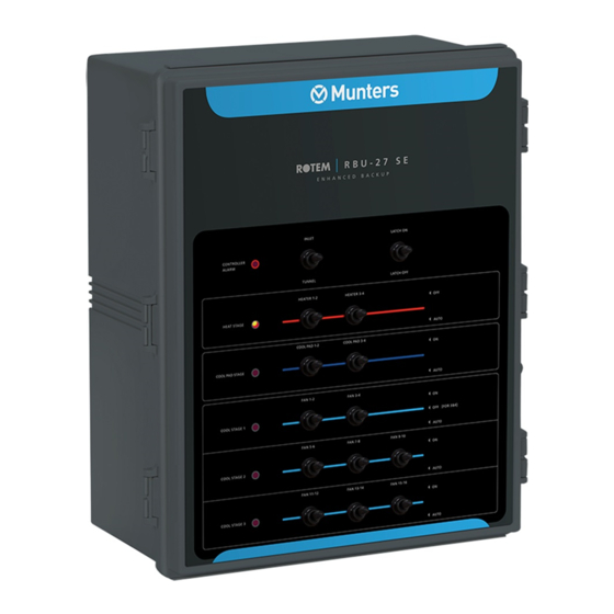
3.1 Switch Functions Figure 2 illustrates the front panel and Table 1 lists the available switch functions. Figure 2: Controller Front Panel When On Controller Alarm Indicates controller failure Heat Stage Heat stage is active Cool Pad Stage Cool pad stage is active Cool Stage 1/2/3 Cool stage is active Table 1: Available Switch Functions... -
Page 7: Rbu-27 Se Functions
Switch Function Comments The Off option prevents heater activity. The Auto Heater 1 – 4 Each stage has its own circuit breaker, and its option activates heaters only if the thermostat Off/Auto own thermostat. temperature set point has been reached. The On option activates the sprayers manually. -
Page 8: Hot Weather Protection
3.2.3 Hot Weather Protection Stage operation: • If the house temperature rises to Thermostat 3’s set temperature, the RBU-27 SE launches Cooling Stage 1 and operates Fans 1-2 and 3-4 to lower temperatures. • If temperature continues to rise to Thermostat 4’s set temperature, the RBU-27 SE launches Cooling Stage 2 (Fans 5-6, 7-8, and 9-10) and uses the Inlet or Tunnel option as well. -
Page 9: Platinum Fail Safe
3.2.4 Platinum Fail Safe In case of a failure in a Platinum controller, the RBU-27 SE: opens the selected air source (Inlet or Tunnel) turns on Fans 1-4 lights the Controller Alarm LED NOTE: Only Platinum Controllers support the Fail Safe feature. WARNING! On the Platinum Front Panel, set the Fail Safe Relay to Auto. -
Page 10: Specifications
4. Specifications Power Supply Mains voltage Single phase 115 VAC 50 - 60 Hz Mains frequency 50/60 Hz Relays Outputs Resistive load 30 A, 277 VAC Housing Polycarbonate UL 94-5V IP 65 Dimensions (L x W x H) 500 x 400 x 200 mm (19.7 x 15.7 x 7.9 inches) Ambient Climate °... -
Page 11: Installation
5. Installation The following sections describe the installation process. • Safety Instructions • Mounting the Unit • Platinum Controller Notes • Wiring • Drilling 5.1 Safety Instructions To protect yourself and your controller, observe the following rules: • ONLY an authorized electrician may install the RBU-27 SE. •... - Page 12 Figure 8: Heater Wiring Figure 9: Fail Safe Wiring Figure 10: Relays Diagram – Inlet / Tunnel – Section 3 Figure 4: Card View Figure 4 presents a view of the card divided into the following main sub-units: Section 1 - Pre-wired sub-units: Designed to be used only in case an error occurs. Only authorized technicians can replace or repair these subunits.
- Page 13 Neutral Inlet Line (L1) Power to Inlet Open1 and Open2 Tunnel Line (L1) Power to Tunnel Tunnel Open Heat Line Thermostat common (TC) Thermostat normally closed (TNC) A similar order applies for other heaters and fans. During normal operation the Platinum Inlet/Tunnel curtain is connected through the RBU-27 SE PWR output (L1). In case of a Platinum failure or in case the RBU-27 SE thermostat reaches the set point (Main Controller failure), the RBU-27 SE takes control and cuts the PWR output to the Platinum and opens Inlet/Tunnel curtain.
- Page 14 Figure 6: Vent Machine Wiring Notes: • During normal operation, the RBU-27 SE connects L1 through PWR to the Platinum relays. During emergencies, the RBU stops supplying power to the Platinum controller. • The RBU-27 SE can only open the vent machines. •...
- Page 15 CAUTION: Connect a safety ground and follow the National Electrical Code! Figure 7: Fan and Cooling Wiring Notes: • The fans connect in standard order (meaning factory labeled) in the RBU-27 SE. • Cool 1 (Platinum Relay) and Cool 2 (Platinum Relay) connect from the Platinum Extension Box to Fan 15 and Fan 16 terminals in the RBU-27 SE.
- Page 16 Figure 8: Heater Wiring Notes: • Connect L1 Power to the RBU-27 SE from the Heater 1 circuit breaker (not shown in diagram). • Back up heaters in the brooding zone (up to 4). • Backup turns heaters on in one zone (one thermostat). Figure 9: Fail Safe Wiring...
- Page 17 Figure 10: Relays Diagram – Inlet / Tunnel – Section 3...
-
Page 18: Drilling
5.5 Drilling Drill several holes on the bottom of the unit. Route the cables through these holes/ Figure 11: Hole locations (example) NOTE: Figure 11 is an example only. The number of holes in each installation depends on the number of cables being run. -
Page 19: Troubleshooting
6. Troubleshooting The following sections detail how to troubleshoot the RBU-27 SE. General Issues Contactors and Terminals Issues 6.1 General Issues Table 3 describes the outputs and their related relays. In case there is a problem check the following before troubleshooting your unit: Voltage Circuit breakers... -
Page 20: Internal Contacts
Figure 12: Shorting the unit 6.2.2 Internal Contacts To check internal contacts: 1. With the power off, disconnect the quick connect from the COM, NO and NC relay terminals (Figure 13). 2. Turn the power back on. 3. Using an Ohm meter, check that the resistance between the COM and NO is zero (0), and the contact between COM and NC is open. - Page 21 Table 5: Detailed Troubleshooting Issues II Contactors K11-20 115V 115V 115V 115V 115V 115V 115V 115V 115V 115V Inputs/Terminals Inlet, All Switches-Auto PP-F Latch short open open open open short open short open open open short open open open open short short open...
- Page 22 Figure 14: Contactor and Terminals Layout Map...
-
Page 23: Appendix A: Adding A Timer Stage
7. Appendix A: Adding a Timer Stage Adding a timer stage to the RBU-27 SE can save fuel costs. Rather than running fans continuously, adding a timer ensures that they are used only when needed. The following diagram illustrates a system consisting of a timer wired to the RBU-27 SE relays coils. Figure 15: Backup Unit with an External Timer The following diagram illustrates a system consisting of a timer and coolers wired to the RBU-27 SE relays coils. - Page 24 Figure 16: Backup Unit with an External Timer and Coolers...
-
Page 25: Appendix B: Electrical Grounding
8. Appendix B: Electrical Grounding Electrical equipment can be destroyed or slowly damaged by voltage spikes, lightning hits, etc. Proper electrical grounding in combination with the RBU-27 SE internal protections is essential for system protection, reduction of systemic damage and prolongs its lifetime. Grounding reduces the risk of human injury. -
Page 26: What Should Be Grounded
Figure 17: Ground Connection 8.4 What Should Be Grounded? Any equipment that is, or could become energized, even accidentally, should be grounded. Electric circuits should be wired with a 3-wire conductor consisting of hot, neutral and grounding wires. The grounding wire should be attached cleanly and securely to devices or systems to be grounded. The other end of the grounding wire should be attached to the ground bus on the main panel. -
Page 27: Warranty & Limitation Of Liability
9. Warranty & Limitation of Liability 1. Rotem warrants that the product shall be free of defects in materials or workmanship and will conform to the technical specification for a period of 1 (one) year from the date of initial installation on site (the "warranty period"). 2.
Need help?
Do you have a question about the Rotem RBU-27 SE and is the answer not in the manual?
Questions and answers