Graco A Series Instructions-Parts List Manual
Overspray masking liquid system, stainless steel, with stainless steel pump
Hide thumbs
Also See for A Series:
- Instructions - parts manual (52 pages) ,
- Instructions-parts list manual (48 pages) ,
- Manual (36 pages)
Table of Contents
Advertisement
Quick Links
Instructions - Parts List
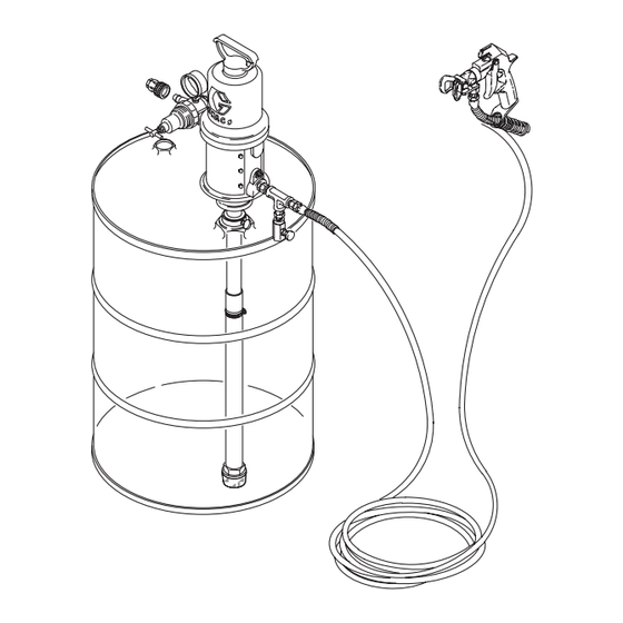
Overspray Masking
Liquid System
For airspray application of fluids. For professional use only.
System
Model 224826
with Stainless Steel Pump*
2700 psi (18.6 MPa, 186 bar) Maximum Working Pressure
80-90 psi (0.55-0.62 MPa, 5.5-6.2 bar) recommended regulated air inlet pressure
Important Safety Instructions
Read all warnings and instructions in this
manual. Save these instructions.
NOTICE
This pump is factory tested in oil. To avoid contami-
nating the masking liquid or the surface being
painted, flush the pump before immersing it in the
masking liquid. Use water only to flush. Paint solvents
will damage the seals. Follow the set-up procedure
carefully, and pay special attention to the Flushing
procedure on page 6.
Pump
Model 224825, Series A
Stainless Steel*
308069P
EN
Advertisement
Table of Contents

Related Manuals for Graco A Series


Summary of Contents for Graco A Series
- Page 1 Instructions - Parts List Overspray Masking Liquid System 308069P For airspray application of fluids. For professional use only. System Pump Model 224826 Model 224825, Series A with Stainless Steel Pump* Stainless Steel* 2700 psi (18.6 MPa, 186 bar) Maximum Working Pressure 80-90 psi (0.55-0.62 MPa, 5.5-6.2 bar) recommended regulated air inlet pressure Important Safety Instructions Read all warnings and instructions in this...
-
Page 2: Table Of Contents
Clearing a Clogged Spray Tip ....10 Graco Standard Warranty ....24 Adjusting the Spray Pattern and Spraying Pressure Practice Spraying . -
Page 3: Warnings
Warnings Warnings The following warnings are for the setup, use, grounding, maintenance, and repair of this equipment. The exclama- tion point symbol alerts you to a general warning and the hazard symbols refer to procedure-specific risks. When these symbols appear in the body of this manual or on warning labels, refer back to these Warnings. Product-specific hazard symbols and warnings not covered in this section may appear throughout the body of this manual where applicable. - Page 4 Warnings WARNING EQUIPMENT MISUSE HAZARD Misuse can cause death or serious injury. • Do not operate the unit when fatigued or under the influence of drugs or alcohol. • Do not exceed the maximum working pressure or temperature rating of the lowest rated system com- ponent.
-
Page 5: Installation
Installation Installation Learn how to use the gun’s trigger safety latch before Pump: use ground wire and clamp (F . 2). Remove the operating the system. ground screw (Z) and insert through the eye of ring ter- minal at end of ground wire (Y). Fasten the ground The high pressure, airless spray gun supplied with this screw back onto the pump and tighten securely. -
Page 6: Setup For Initial Flushing
Installation 4. Two 5 gallon flushing containers, one with warm 2. Remove the quick-disconnect coupler from the nip- soapy water, and one with cool, clean water. ple. To disconnect, pull back on the sleeve of the coupler and pull it away from the nipple. Screw the coupler onto the air line. -
Page 7: Pump Installation
Installation 11. Raise the pump out of the pail. Trigger the fun to 5. Slide the suction hose and pump through the bung force the water from the system. DO NOT run the hole in the drum cover. Before the final positioning pump dry for more than 10 seconds to avoid damag- of the pump, screw the bung adapter firmly into the ing the pump packings. -
Page 8: Operation
Operation Operation TIP GUARD SPRAY AIR LINE QUICK DISCONNECT COUPLER QUICK DISCONNECT NIPPLE AIR REGULATOR & GAUGE DRAIN VALVE DETAIL TIGHTEN TO CLOSE Pressure Relief Procedure 5. Place a pail under the drain valve and open the drain valve to be sure all fluid pressure is relieved. Follow the Pressure Relief Procedure whenever NOTE: If you suspect that the tip guard or hose is you see this symbol. -
Page 9: Selecting A Tip
Operation 6. Hold a metal part of the gun firmly against and 1. Be sure the trigger safety latch is engaged. aimed into a grounded metal pail. Squeeze the gun 2. Install the tip cylinder. Hold the cylinder with the trigger and hold it open. -
Page 10: Changing Spray Tips
Operation 5. Screw the retaining nut snugly onto the gun, holding Adjusting the Spray Pattern and the tip guard in the desired direction while tightening Spraying Pressure the nut. See Step 4 of Adjusting the Spray Pattern and Spraying Pressure on page 10 for more infor- Refer to F . -
Page 11: Practice Spraying
Operation Practice Spraying 2. Keep gun moving horizontally or vertically at a steady rate. Read the spray techniques in Steps 1-5 below and F 3. Release trigger just as you approach other edge of 10 and F . 11, and follow 3M’s recommendations on target surface, but keep the gun moving until it has application of the masking liquid. -
Page 12: Maintenance
Maintenance Maintenance 3. Pour 4 gallons of warm water into the empty 3M container. 4. Move the pump to the flushing container. 1. Keep the pump and hose fully primed with the masking liquid when it is not in use. This is done by 5. -
Page 13: Pump Packing Nut Adjustment
Maintenance 3. Trigger the gun into the flushing container. When 3. Check to see that the air motor piston is at the top of mineral spirits appear at the fun, release the trigger the stroke. If it is not, while keeping your fingers and set the trigger safety latch. -
Page 14: Troubleshooting
Troubleshooting Troubleshooting NOTE: Check all other possible problems and solutions before disassembling the pump. Never operate the pump with the warning plate (20) or the identification plate (40) removed. These plates protect your fingers from pinching or amputation by moving parts in the air motor. Problem Cause Solution... - Page 15 Troubleshooting Problem Cause Solution Packing nut too tight Loosen packing nut Packing worn/material dried on I.D. Pump chattering Inspect/replace packing of packing Material dried on rod Clean or replace rod No material Fill or replace container Air leak between intake valve and Tighten or replace clamp or hose suction tube (55 gallon unit only) Pump fails to prime...
-
Page 16: Service
Service Service Before Starting Have all necessary parts on hand. Always replace the glands and bearing when replacing the packings. Use all the parts in the repair kits for the best results. Air Motor and Throat Disassembly 1. Flush the pump and relieve the pressure. See Pres- sure Relief Procedure on page 8. -
Page 17: Air Motor And Throat Reassembly
Service Air Motor and Throat PUSH TOGGLES (M) IN Reassembly AND THEN UP (SHOWN IN THE DOWN POSITION HERE) TURN WIRES UP 1. Clean all the parts in a compatible solvent and inspect for wear or damage. Check the polished sur- To remove faces of the piston, piston rod, and cylinder wall for toggles,... -
Page 18: Displacement Pump Disassembly
Service 5. Install the grommets (32) in the valve actuator (35). Displacement Pump Install the trip rod (54) in the piston (59). Place the Disassembly trip rod yoke (28) and valve actuator (35) on the trip rod. Be sure the o-ring (36) is in place and that the valve actuator is supported by the spring clips (58), and then reassemble the valve mechanism. -
Page 19: Displacement Pump Reassembly
Service Displacement Pump Reassembly 1. Clean and inspect the parts and replace any that are worn or damaged. Be sure to check the copper gasket (46) in the motor base (55). Lubricate the parts with a light, waterproof grease. 2. Install the seal (16), packing (17), bearing (18), gas- ket (6), seat (19), and ball (2) on the piston body (13). -
Page 20: Parts
Parts Parts Model 224825, Series A LIPS OF V–PACKINGS MUST FACE DOWN 308069P... - Page 21 Parts Model 224825, Series A Ref. Part Description Qty. 160623 ARM, toggle Ref. Part Description Qty. 160624 O-RING, nitrile rubber 2❖ 103075 BALL, sst, 0.44 in (11.2 mm) dia 39❄ 160625 O-RING, nitrile rubber 3❖ 101859 BALL, sst, 0.75 in (19 mm) dia 40†...
- Page 22 Parts Model 224826, Stainless Steel System Ref. Part Description Qty. Ref. Part Description Qty. 286621 SPRAY TIP, size 621, installed in tip 224825 15:1FIRE-BALL ® 300 PUMP, See guard pages 22 and 23 for parts, includes 243161 TIP GUARD, RAC V items 1a to 1d 224022 SUCTION HOSE, includes items 166421 NIPPLE, 1/4 npt...
-
Page 23: Technical Data
Technical Data Technical Data Overspray Masking Liquid System Metric Maximum fluid working pressure 2700 psi 18.6 MPa, 186 bar Air pressure operating range 40-180 psi 0.3-1.2 MPa, 3-12 bar Fluid pressure ratio 15:1 Air motor effective diameter 76 mm 3 inches Stroke 3 inches 76 mm... -
Page 24: Graco Standard Warranty
With the exception of any special, extended, or limited warranty published by Graco, Graco will, for a period of twelve months from the date of sale, repair or replace any part of the equipment determined by Graco to be defective.
Need help?
Do you have a question about the A Series and is the answer not in the manual?
Questions and answers