EMS AirFlow S1 Service Manual
Hide thumbs
Also See for AirFlow S1:
- Quick start manual (2 pages) ,
- Operation instructions manual (92 pages) ,
- Operation instructions manual (98 pages)
Table of Contents
Advertisement
Advertisement
Table of Contents

Related Manuals for EMS AirFlow S1


Summary of Contents for EMS AirFlow S1
- Page 1 AirFlow ® Service manual ELECTRO MEDICAL SYSTEMS...
- Page 2 AirFlow ®...
-
Page 3: Table Of Contents
Replacement of the pinch valve Spare parts & Update Spair part View 33-35 Function control Safety control EMS reserves the right to modify the technic, accessories, operating instructions or the contents of the AirFlow S1 due to technical or scientific improvements. ®... - Page 4 AirFlow ®...
-
Page 5: Important Note
EMS. All repairs or revisions must be carried out with the original EMS spare parts. The EMS quality policy requires a function control for each inter- vention and a safety control for each intervention requiring the opening of the unit. -
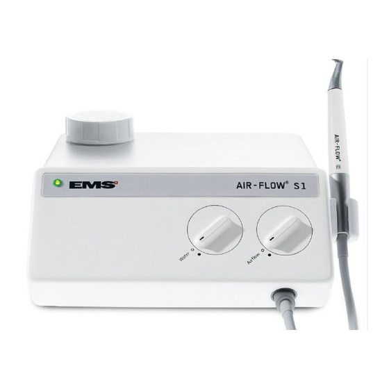
Page 6: The Unit And Its Components
AirFlow ® The unit and its components Installation Mains 100 - 110 V AC Mains 220 - 240 V AC Water pressure 1 - 5 bar Compressed air 4.5 - 7 bar Polisher handpiece Spanner for water filter Footswitch Installation The following connections are required to operate the unit : A water supply of between 1 and 5 bars... -
Page 7: Technical Data
Technical data Technical data Manufacturer: EMS SA - 1260 Nyon, Switzerland Models: AirFlow ® Classification: EN 60601-1 Class I Type B IP 20 93/42 CEE: Class IIa Mode of operation: Continuous operation Supply voltage: 100 V AC / 110 V AC... -
Page 8: Description Of The Electrical Parts
AirFlow ® Description of the electrical parts This unit is equipped with a mains socket with fuses incor- porated. The main switch ON/OFF is placed on the back side of the unit. The mains voltage (high voltage of 110, 220 or 240 V AC) is converted into 24V AC (low voltage), by an internal trans- former, to supply all the electrical components of the unit. - Page 9 AirFlow ® Primary circuit (high voltage) Transformer Secondary fuse Main switch T 2.5A Mains socket 240 V Black 130 V ON/OFF 220 V T 1A Blue Primary fuses 24 V AC 110 V AC 110 V T 1A Blue Black Yellow/Green Yellow/Green Transformer...
-
Page 10: Description Of The Hydraulic Parts
AirFlow ® Description of the hydraulic parts AirFlow S1 is equipped with a water filter at the entrance ® of the water supply. Water circuit is made by blue hoses. On the AirFlow unit, the water passes through a water ®... -
Page 11: Description Of The Pneumatic Parts
AirFlow ® Description of the pneumatic parts AirFlow S1 unit is driven by a pneumatic footswitch. Internal air ® circuit is made by yellow hoses. It is equipped with an air filter at the entrance of the air supply. The air passes through a regulator allowing the regulation of the flow, and goes into the a set of two air filters before its entrance into the powder bowl. -
Page 12: Description Of The Powder Parts
AirFlow ® Description of the powder parts The powder circuit is used on the AirFlow system. The ® powder circuit is made by a transparent hose. The powder comes from the powder bowl and passes through the pinch valve allowing the stop of the flow, and goes into the polisher handpiece via the handpiece cord. - Page 13 Notes Remarks and observations...
-
Page 14: Trouble Shooting
AirFlow ® Trouble shooting ° ° ≤ ≤ ≤ ≤ ≤ ≤ ≤ ≤ Replacement do not need the opening of the unit... -
Page 15: Opening Of The Unit
Opening of the unit Remove the screw (83) and open the upper casing by lifting up from the closed position. The assembly of the upper part and the lower part of the unit is made by the hinge (86). -
Page 16: Verification Of The Air Circuit
AirFlow ® Replacement do not need the opening of the unit Disconnecting of the air, water and powder hoses In all cases, remove first the external collar and after the conical part of the uniclamp (92). Remove the hose (66, 70 or 85) from the tubing of the ele- ment. -
Page 17: Replacement Of The Secondary Fuses
Replacement of the secondary fuse Turn the fuse holder head (82) on the anticlockwise and extract the fuse (81). Replace the fuse following the specifications mentioned on the sticker. Sticker Unsoldering of the electricawires In all cases, before to unsolder the wires on the electrical connexion, remove the insulated sleeving. -
Page 18: Replacement Of The Primary Fuses
AirFlow ® Replacement of the primary fuses Open the unit (see page 15). Apply a lateral slight pressure with a small screwdriver on the fuse holder (78) and extract the fuses (77). Replace the fuses following the specifications mentioned on the sticker at the rear of the unit. Sticker... -
Page 19: Assembly Of The Knob
Assembly of the knob The regulators and taps sent for After Sales Support are ADJUSTED and TESTED to function correctly. Don’t modify the adjustment before assembly. Preparation of the regulator holder Cut the three external pins coming from the moulding. Lay down a film of silicone paste on the contact surface between the knob and the holder. -
Page 20: Replacement Of The Transformer
AirFlow ® Replacement of the transformer Remove the three screws (90) of the metal housing of the transformer (64). Remove the housing of the transformer and extract the bushing (93). Remark: note the order of connection for each wire. Unsolder all the electrical cables of the transformer (65). Remove the four screws (83) and the washers (74) of the transformer. -
Page 21: Replacement Of The Thermostats
Replacement of the thermostats This procedure is identical for the thermostat 60 C (28) and for the thermostat 47 C (29) screwed on the top of the water heater (30). Remove the thermostat protection (27). Unsolder the two cables on the thermostat. Unscrew the thermostat using the two pins for electrical connection. -
Page 22: Replacement Of The Water Heater
AirFlow ® Replacement of the water heater Remove the three screws (90) of the metal housing of the transformer (64). Remove the housing of the transformer and extract the bushing (93). Unsolder the electrical wires on pin 11 of the transformer (65) and extract the electrical wire of the water heater from the bushing. -
Page 23: Procedure In Case Of Heating Problem
Procedure in case of heating problem Switch the power ON and verify (by hand) the increase of temperature of the water heater (30). If the heater stays cold, use the following procedure to identify if the problem is due or not to the thermostats. Shunt (A) the thermostat 47 C (29) and control the increase of temperature of the heater. -
Page 24: Replacement Of The Water Filter Cartridge
AirFlow ® Replacement of the water filter cartridge Unscrew the cap of the water filter (38) on the back side of the unit. Unscrew the water filter cartridge using the hexagonal spanner (10). Change the water filter spare parts set (39). Replacement of the complete water filter Dismantle the uniclamp (92) and disconnect the blue water hose (70) from the water filter. -
Page 25: Replacement Of The Water Regulator
Replacement of the water regulator Dismantle the two uniclamps (92) and disconnect the blue water hoses (70) from the regulator. Remove the two screws (90) and the elastic washers (89) of the knob. Extract the water regulator (91) and the knob (68) from inside of the casing. -
Page 26: Replacement Of The Pneumatic Module For Polisher
AirFlow ® Replacement of the pneumatic module for polisher Remove the two screws (63) and the washers (26). Release the electrovalve (23) and its plate (21). Extract the selector rod (22) from the module. Remove the five uniclamps (92) and disconnect the three yellow air hoses (66) and the two blue water hoses (70) from the pneumatic module for polisher (62). -
Page 27: Replacement Of The Air Filter Element
Replacement of the air filter element Unscrew the air filter bowl (59). Unscrew the air filter element (60). Change the air filter element and the O-ring. Replacement of the air filters This procedure is identical for : - the air filter with horizontal L coupling (58), - the air filter with check-valve (55), - the air filter with vertical L coupling (54). -
Page 28: Replacement Of The Electrovalve
AirFlow ® Replacement of the electrovalve Remove the two screws (63) and the washers (26). Release the plate support (21) of the electrovalve and re- move the two plastic screws (20). Disconnect the three electrical connectors from the elec- trovalve. Disconnect the four uniclamps (92) and the yellow air hoses (66) from the electrovalve (23). -
Page 29: Replacement Of The Air Regulator
Replacement of the air regulator Remove first the two screws (63) and the washers (26) of the pneumatic module for polisher to allow a free access to the fixation of the air regulator. Dismantle the two uniclamps (92) and disconnect the yellow air hoses (66) from the regulator. -
Page 30: Replacement Of The Powder Bowl Set
AirFlow ® Replacement of the powder bowl set Unscrew the cap for powder bowl (56) from outside of the unit. Remove the two screws (34) and the washers (26). Dismantle the two uniclamps (92) and disconnect the yellow air hose (66) and the transparent powder hose (85) from the powder bowl set (35). -
Page 31: Replacement Of The Pinch Valve
Replacement of the pinch valve Remove the two screws (25) and the washers (26). Dismantle the two uniclamps (92) and disconnect the trans- parent powder hose (85) from the polisher connector (48). Remove the transparent powder hose passing through the pinch valve hole. -
Page 32: Spare Parts & Update
AirFlow ® Spare parts & Update -The Spare parts catalogue #1 dent refer to FM-058/* - AF Handpiece EL-085 + EL-086 + EM-061 are Discontinued Replace by EQ-160 The solnoide valv EQ-024 replace by EQ-159 -The powder tube BG-006 replace by EQ-207... -
Page 33: Spair Part View
AirFlow ®... - Page 34 AirFlow ®...
- Page 35 AirFlow ® Pos. Designation Order No. Pos. Designation Order No. Pos. Designation Order No. Plastic screw for electrovalve DD-037 Air filter - horizontal L coupling EQ-065 Plate for electrovalve BE-003 Air filter bowl + O-ring EQ-020 Selector rod EQ-023 Kit Air filter element + O-ring EQ-152 Electrovalve EQ-159...
-
Page 36: Function Control
Service in Nyon for information. Uae the Deat Sheet fonction control ZA-176. Safety control The EMS quality policy requests a safety control for each repair requiring the opening of the unit. Use the safety control procedure of the SAV FM-010. - Page 37 Notes Remarks and observations...
- Page 38 Notes Remarks and observations...
- Page 40 SWITZERLAND EMS SA, Ch. de la Vuarpillière 31, CH-1260 Nyon Tel. +41 22 99 44 700, Fax +41 22 99 44 701 e-mail: welcome@ems-ch.com website: www.emsdent.com...
Need help?
Do you have a question about the AirFlow S1 and is the answer not in the manual?
Questions and answers