Table of Contents
Advertisement
Quick Links
Advertisement
Table of Contents

Subscribe to Our Youtube Channel
Related Manuals for EMS DOLORCLAST RADIAL


Summary of Contents for EMS DOLORCLAST RADIAL
- Page 1 INSTRUCTIONS FOR USE INSTRUCTIONS FOR USE...
- Page 2 DOLORCLAST RADIAL ® ENGLISH ............... 3...
-
Page 3: Table Of Contents
11. ELECTROMAGNETIC COMPATIBILITY .. 32 2. GETTING STARTED........10 12. PRODUCT DISPOSAL ......36 2.1. STARTING THE DEVICE ......... 10 13. EMS TECHNICAL SUPPORT ....36 2.2. INTERFACES ........... 10 14. WARRANTY..........36 2.3. SOFTWARE AND HANDPIECE INFORMATION (NUMBERS OF USE) ..... 12 15. -
Page 4: Please Read This First
Indications for Use installation and use of this product. Always keep these instructions close at hand. The DolorClast Radial is intended for relief of minor muscle aches and pains, temporary increase in local blood circulation, and activation of connective tissue. -
Page 5: Contraindications
Contraindications Precautions Do not use this device under these conditions: ALWAYS move the handpiece over the treatment zone. This enables visual feedback of potential • Treatment over air-filled tissue (lung, gut), side effects such as redness, petechias, or • Treatment of pre-ruptured tendons, bruising. -
Page 6: Installation
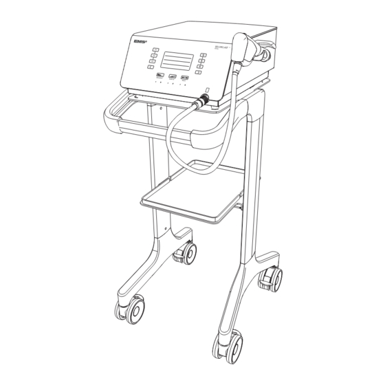
1. INSTALLATION 1.1. COMPONENTS The components provided with your device will vary, according to your configuration. Figure 1 DESIGNATION Console Handpiece with 15-mm applicator (applied part) Applicator set (see details in next page) Cart - Optional Handpiece holder kit Power cord Gel bottle O-ring maintenance kit Piston maintenance kit... - Page 7 15-mm Applicator, Trigger – Optional 15-mm Applicator, Focus – Optional 25-mm Applicator - Optional 5-mm Applicator - Optional *EMS recommends to clean and disinfect the applicator prior to treating a patient. Please refer to instructions in section 7. Figure 3 DESIGNATION...
-
Page 8: Installing The Console
3. Secure the console to the cart using the dedicated 1.2. INSTALLING THE CONSOLE thumbscrew. Install the console on a fl at, stable surface or use the cart (optional) designed for the console. 1.2.1. Installing the Console on the Cart All screws have to be pre-assembled without tightening them at fi rst. -
Page 9: Connecting The Console To The Equipotential Conductor
2. Place the handpiece on the handpiece holder. 1.3. CONNECTING THE CONSOLE TO THE EQUIPOTENTIAL CONDUCTOR When applicable and according to your in-house protocol, connect the equipotential conductor at the rear of the console with the bus bar. The equipotential cable is not supplied with the console. -
Page 10: Getting Started
2. GETTING STARTED 2.1. STARTING THE DEVICE The mains power switch of the product must be accessible at any time, to allow disconnection of the device. 1. Use the mains power switch located on the left side panel to switch on the console. Figure 13 2.2. - Page 11 BUTTON MEANING ACTION Minus button Use this button to decrease the value displayed on the screen. 2500 Plus button Use this button to increase the value displayed on the screen. Impulses SMART PROTOCOL Preset protocol Use these buttons to select a preset protocol. 2500 navigation buttons (See 5.
-
Page 12: Software And Handpiece Information (Numbers Of Use)
Changing the language will reset to factory set- Figure 17 tings. If you have saved a USER protocol, it will be deleted. EMS does not guarantee the performance of the treatment if the piston has reached its maximum recommended pulses. 3. Press to confirm that you wish to perform a factory reset/change the language. -
Page 13: Stopping The Device
4. Press the buttons to select the appro- priate language. Figure 20 5. To display more languages, use the button to view additional language options on subsequent pages. 2.5. STOPPING THE DEVICE 1. Use the mains power switch located on the left side panel to switch off the console Figure 21... -
Page 14: Treatment
Use EMS SWISS DOLORCLAST coupling gel ® Figure 22 for best results. Thanks to its special viscosity, the EMS gel transmits pressure pulses without Use biofeedback from the patient to localize the leaking to ensure a perfect transmission through- affected muscle. out treatment. - Page 15 1. Ensure the O-ring is still in place with the spare appli- 3.2.2. Adjusting the Pressure cator. If the O-ring is disconnected from the applicator, replace it. To adjust the shock wave depth and the energy trans- mitted into the tissue, increase or decrease the pressure. The pressure can be selected between 1 and 4 bar, in increments of 0.1 bar.
- Page 16 2. Select the size of the applicator used for treatment. 3.2.4. Adjusting the Number of pulses To adjust the total number of pulses transmitted to the patient, increase or decrease the number of pulses. The 5 mm 10 mm number of pulses can be selected between 500 and 5000, 15 mm 15 mm Trigger in increments of 500.
-
Page 17: Performing Treatment
To maximize treatment effi ciency, we recommend holding The QR code of your console screen will lead you the handpiece with two hands, in two different ways: to an appropriate EMS contact page. • One hand up and one hand down... - Page 18 Figure 39 2. Once you start treatment and as you move the appli- cator around the treatment area, ask the patient to tell you if the treatment becomes uncomfortable and adjust the device settings accordingly. The application force exerted manually varies and depends on the indication.
-
Page 19: Preset Protocols
4. PRESET PROTOCOLS 4.1. DESCRIPTION OF PRESET PROTOCOLS You can use preset protocol settings as a starting point instead of adjusting each parameter of the default setting. Preset protocols are available to help you target treatment and increase effi ciency. The 4 preset protocols are: PRESET PROTOCOLS FACTORY SETTINGS... -
Page 20: Saving Adjusted Preset Protocols
4.4. SAVING ADJUSTED PRESET PROTOCOLS You can easily save the settings you customized for a given preset protocol. 1. To record the newly customized settings for a given preset protocol, press and hold the buttons simultaneously for 2 seconds. 2500 Impulses SMART Protocol 2* Figure 42... -
Page 21: Special Modes
5. SPECIAL MODES ANALGESIC [0 mJ/mm Only one special mode can be activated at a time. ANALGESIC [0 mJ/mm All settings associated with the special modes are 1000 preset and cannot be changed. Impulses 1000 Impulses SMART PROTOCOL SMART PROTOCOL 5.1. -
Page 22: Ramp-Up Modes
ANALGESIC [0 mJ/mm ANALGESIC [0 mJ/mm 1000 1000 Impulses Impulses SMART PROTOCOL SMART PROTOCOL Figure 47 1. Before starting treatment or after a pause, press the Ramp-Up button to enable Ramp-Up mode 1. The LED signifi es that the mode is enabled. Figure 46 3. -
Page 23: Burst Modes
5.3. BURST MODES Use the Burst modes to prevent the patient from devel- oping tolerance to certain mechanical stimuli. The Burst modes are specifi cally designed to alternate a preset frequency and a maximum frequency during treatment. 5.3.1. Burst Mode 1 Using Burst mode 1 during treatment will automatically Figure 49 alternate between 4 seconds at the set frequency and... - Page 24 5.3.2. Burst Mode 2 Burst mode 2 makes it possible to manually switch between a set frequency and a frequency of 25Hz. Figure 53 1. Press the Burst button twice to activate Burst mode 2. The LED signifi es that the mode is enabled. 1000 Impulses 1000...
-
Page 25: Cleaning And Disinfecting
6. CLEANING AND DISINFECTING 1. Disassemble the applicator, the nose, the retaining 6.1. HANDPIECE nut and the o’rings. We advise to clean and disinfect the handpiece after each treatment 1. Clean and Disinfect with a cleaning and disinfectant wipe such as Surface Wipes Zero from Helvemed, or equivalent (quaternary ammonium as active... -
Page 26: Maintenance
Figure 57 The QR code that will appear on your console screen will lead to an EMS website allowing you to order a new piston. To change the piston, proceed as following: Figure 60 1. - Page 27 Pull on the piston to remove it from the handpiece. 5. Install the new piston on the handpiece. 6. Re-assemble the handpiece. 7.1.2. Applicator O-ring EMS recommends to change the o’rings when the piston is changed 7.1.2.1. For 5-mm, 10-mm and 15-mm Applicators 1. Disassemble the applicator.
- Page 28 7.1.2.2. For 25-mm and 40-mm Applicators Figure 66 DESIGNATION QUANTITY Figure 70 O-rings Applicator DESIGNATION QUANTITY Nose Nose O-rings Applicator 1. Place the O-ring 1a on the applicator. 2. Place the O-ring 1b on the applicator. 1. Remove the applicator from the handpiece. Figure 67 3.
- Page 29 3. Fit the large wrench on the applicator and hold the 6. Remove the nose. support with your hand. Turn the wrench to loosen the nut. Figure 76 Figure 73 7. Remove the second large O-ring. 4. Finish unscrewing the nut manually and remove it from the applicator.
- Page 30 9. To assemble the O-rings , place the O-ring on the 12. Place the applicator on the nose. groove of the applicator. Figure 79 Figure 83 Ensure the O-ring is correctly positioned. 13. Place the O-ring on the applicator. Figure 80 Figure 84 10.
-
Page 31: Console
5. Insert the fuse drawer. 7.2.1. Replacing Fuses 6. If the fuses fail again, please contact your EMS autho- rized service center. 1. Switch off the device. 2. Disconnect the power cord at the rear of the console. -
Page 32: Compatibility With Dolorclast ® Product Range
9. COMPATIBILITY WITH DOLORCLAST PRODUCT RANGE ® The Dolorclast Radial device and the BLUE handpiece are designed to be used together. The BLUE handpiece can ® not be used with legacy Dolorclast systems. ® 10. PRODUCT STORAGE AND SHIPPING Storage and transport conditions are specified in Should you wish to store or ship your product: the “Technical Data”... - Page 33 Guidance and Manufacturer’s Declaration – Electromagnetic Emissions The DOLORCLAST Radial is intended for use in the electromagnetic environment specified below. The customer ® or the user of the DOLORCLAST Radial should assure that it is used in such an environment. ®...
- Page 34 Guidance and Manufacturer’s Declaration – Electromagnetic Immunity The DOLORCLAST Radial is intended for use in the electromagnetic environment specified below. The customer ® or the user of the DOLORCLAST Radial should ensure that it is used in such an environment. ®...
- Page 35 28.0 - 29.7 MHz and 50.0 - 54.0 MHz. Table 6 Compliant Cables and Accessories The use of accessories and cables other than those specified or sold by EMS as replacement parts may result in increased emissions or decreased immunity of this product. CABLES AND...
-
Page 36: Product Disposal
(see below) for any product servicing or repairs. You must complete the appropriate EMS form in order to be Repair can be refused for products or accesso- issued with a Return Material Agreement (RMA) number. -
Page 37: Technical Description
15. TECHNICAL DESCRIPTION MANUFACTURER EMS ELECTRO MEDICAL SYSTEMS SA, CH-1260 Nyon, Switzerland MODEL DOLORCLAST Radial ® POWER SUPPLY 100-240 VAC, 50-60 Hz, 500VA CLASSIFICATION EN 60601-1 System: class I Applied part type BF RADIO COMMUNICATION RFID 13.56MHz, < 20dBuA/m MDD 93/42 EEC CLASSIFICATION... - Page 38 ACOUSTIC CHARACTERIZATION DATA Note: The data are measured at the maximum pressure setting of 4 bar. 15mm 15mm Applicator 15mm 10mm 25mm 40mm Trigger Focus Type of Acoustic Pneumatic/ballistic Wave Generation Number of pulses Variable as set by operation per treatment Max 5 000 pulses/treatment Penetration depth [mm]...
-
Page 39: Symbols
16. SYMBOLS Manufacturer logo DOLORCLAST Product name RADIAL Manufacturer Catalogue number Serial number Date of manufacture Input power Risk of electric shock CE symbol refers to directive 93/42/EC, including EN 60601-1 and EN 60601-1-2 Device requiring protective earth Refer to the instruction manual Disposal of old electrical &... - Page 40 Recyclable EMS website Fragile Keep away from rain Content Vertical position Expiry date Maximum humidity of 85% Transport temperature condition from +1°C to +30°C Prescription device ANATEL certification number 16208-21-14386 16208-21-14386...
-
Page 41: Appendix
17. APPENDIX Treatment Locations The treatment should be conducted with the adequate applicator regarding treatment surface. The small applicators (5mm, 10mm, 15mm) are better suited for small surfaces such as small tendons or joints. The larger applicators (25mm and 40mm) are the best options for treating larger surfaces such as large muscles or joints. The default protocols provide quick access to different standard parameters. - Page 42 FCC STATEMENTS Any changes or modifications not expressly approved by Electro Medical Systems for compliance could void the user’s authority to operate this equipment. This device complies with FCC radiation exposure limits set forth for general population. This device must not be co-located or operating in conjunction with any other antenna or transmitter.
- Page 45 EMS worldwide offices (medical) Affiliates FRANCE SPAIN SWITZERLAND EMS France Sarl EMS Electro Medical Systems España SLU EMS Electro Medical Systems S.A. 32, Route de Pontarlier c/Tomás Bretón, 50-52, 2ª planta Chemin de la Vuarpillière, 31 F-39460 Foncine-le-Haut E-28045 Madrid 1260 Nyon, Suisse Tél.
Need help?
Do you have a question about the DOLORCLAST RADIAL and is the answer not in the manual?
Questions and answers