
Related Manuals for OLIMEX LPC-P11C24


Summary of Contents for OLIMEX LPC-P11C24
- Page 1 LPC-P11C24 CORTEX-M0 Development board USER’S MANUAL Revision C, March 2013 Designed by OLIMEX Ltd, 2012 All boards produced by Olimex LTD are ROHS compliant...
- Page 2 This document is intended only to assist the reader in the use of the product. OLIMEX Ltd. shall not be liable for any loss or damage arising from the use of any information in this document or any error or omission in such information or any incorrect use of the product.
-
Page 3: Table Of Contents
1. Introduction to the chapter ......................1.1 Features ............................1.2 Target market and purpose of the board ................. 1.3 Organization ..........................CHAPTER 2: SETTING UP THE LPC-P11C24 BOARD ........2. Introduction to the chapter ......................2.1 Electrostatic warning ......................... 2.2 Requirements .......................... - Page 4 OLIMEX© 2012 LPC-P11C24 user's manual 6.12.6 CAN_T ........................... 6.13 Additional hardware components ..................CHAPTER 7: BLOCK DIAGRAM AND MEMORY ..........7. Introduction to the chapter ......................7.2 Processor block diagram ......................7.3 Physical memory map ....................... CHAPTER 8: SCHEMATICS ..................
-
Page 5: Chapter 1: Overview
Thank you for choosing the LPC-P11C24 development board from Olimex! This document provides a user’s guide for the Olimex LPC-P11C24 board. As an overview, this chapter gives the scope of this document and lists the board’s features. The document’s organization is then detailed. -
Page 6: Organization
OLIMEX© 2012 LPC-P11C24 user's manual 1.3 Organization Each section in this document covers a separate topic, organized as follows: – Chapter 1 is an overview of the board usage and features – Chapter 2 provides a guide for quickly setting up the board and software notes –... -
Page 7: Chapter 2: Setting Up The Lpc-P11C24 Board
CHAPTER 2: SETTING UP THE LPC-P11C24 BOARD 2. Introduction to the chapter This section helps you set up the LPC-P11C24 development board for the first time. Please consider first the electrostatic warning to avoid damaging the board, then discover the hardware and software required to operate the board. -
Page 8: Powering The Board
OLIMEX© 2012 LPC-P11C24 user's manual 2.3 Powering the board The board is powered via the PWR jack by 7 to 9 volts (preferably closer to the upper limit if you use all peripherals and GPIOs). When powered by 9V the current measured is around 40mA. The red, green and yellow leds (PWR LED, LED1 and LED2) turn on. -
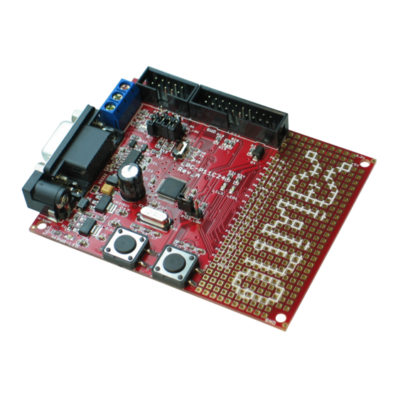
Page 9: Chapter 3: Lpc-P11C24 Board Description
3. Introduction to the chapter Here you get acquainted with the main parts of the board. Note the names used on the board might differ from the names used below to describe them. For the actual names check the LPC-P11C24 board itself. -
Page 10: Chapter 4: The Lpc11C24 Microcontroller
CHAPTER 4: THE LPC11C24 MICROCONTROLLER 4. Introduction to the chapter In this chapter is located the information about the heart of LPC-P11C24 – its microcontroller. The information is a modified version of the datasheet provided by its manufacturers. 4.1 The microcontroller ... - Page 11 OLIMEX© 2012 LPC-P11C24 user's manual ✔ 12 MHz internal RC oscillator trimmed to 1 % accuracy that can optionally be used as a system clock. ✔ Crystal oscillator with an operating range of 1 MHz to 25 MHz. ✔ Programmable watchdog oscillator with a frequency range of 7.8 kHz to 1.8 MHz.
-
Page 12: Chapter 5: Control Circuity
12 MHz quartz crystal Q1 is connected to pins 6 and 7 of the LPC11C24 processor. 5.3 Power supply circuit The power supply circuit of LPC-P11C24 allows flexible input supply from 7V to 9V. This means a wider range of power supplies, adapters, converters are applicable. The maximum amperage recommended is 1A by default. -
Page 13: Chapter 6: Connectors And Pinout
OLIMEX© 2012 LPC-P11C24 user's manual CHAPTER 6: CONNECTORS AND PINOUT 6. Introduction to the chapter In this chapter are presented the connectors that can be found on the board all together with their pinout and notes about them. Jumpers functions are described. Notes and info on specific peripherals are presented. -
Page 14: Uext Connector
OLIMEX© 2012 LPC-P11C24 user's manual 6.2 UEXT connector LPC-P11C24 board has a UEXT connector and can interface Olimex's UEXT expansion modules. For more information on UEXT please visit: https://www.olimex.com/Products/Modules/UEXT/ UEXT connector Pin # Signal Name 1 +3.3V 2 GND 3 TXD... - Page 15 OLIMEX© 2012 LPC-P11C24 user's manual GPIO connector hardware [Name], Processor pin# Pad name [Name], Processor pin# name P0_0 RST, 3 P0_1 ISP_E, 3 P0_2 10 P0_3 PIO0_3, 14 P0_4 SCL, 15 P0_5 SDA, 16 P0_6 23 P0_7 B1, 24 P0_8 27...
-
Page 16: Rs232
Not Connected Not Connected 6.5 PWR Jack The power jack used is the typical 2.5mm one used by Olimex in most of our products. You should provide between 7 and 9 volts @ 1A to the board. Pin # Signal Name... -
Page 17: Can Interface
OLIMEX© 2012 LPC-P11C24 user's manual 6.8 CAN interface There is a CAN connector for controller area network. Pin# SIGNAL NAME Processor Pin# CANL (low) CANH (high) 6.12 Jumper description Please note that the jumpers on the board are either PTH or SMD type. For setting the SMD jumpers please consider that if you feel insecure of your soldering/cutting technique it is better not to try to adjust those jumpers. -
Page 18: Silent/Normal
When open CAN terminator (2x62 Ohm) is disconnected. The default position is closed. 6.13 Additional hardware components The components below are mounted on LPC-P11C24 but are not discussed above. They are listed here for completeness: Reset button - used for hardware reset of the board... -
Page 19: Chapter 7: Block Diagram And Memory
OLIMEX© 2012 LPC-P11C24 user's manual CHAPTER 7: BLOCK DIAGRAM AND MEMORY 7. Introduction to the chapter On the next page you can find a memory map for this family of processors. It is strongly recommended to refer to the original datasheet released by NXP for one of higher quality. -
Page 20: Physical Memory Map
OLIMEX© 2012 LPC-P11C24 user's manual 7.3 Physical memory map This is the memory map diagram from the original datasheet of LPC 11C24. Note that Cx4 processors have 32kB flash memory. Page 20 of 26... -
Page 21: Chapter 8: Schematics
In this chapter are located the schematics describing logically and physically LPC-P11C24. 8.1 Eagle schematic LPC-P11C24 schematic is visible for reference here. You can also find them on the web page for LPC-P11C24 at our site: https://www.olimex.com/Products/ARM/NXP/LPC-P11C24/. They are located in HARDWARE section. - Page 22 OLIMEX© 2012 LPC-P11C24 user's manual TRACE POWER SUPPLY BUTTONS 1N5819S +5V_JTAG DEBUG INTERFACE: 5V_DIS VIN_1 3.3V 3.3V 3.3V VR2(5V) VR1(3.3V) LM1117IMPX-ADJ LM1117IMPX-ADJ 3.3V 1N5819S 1N5819S 3.3V_1 ADJ/G ND ADJ/GND 7-9 VDC 220/1% 240/1% YDJ1136 WAKE_UP WAKE_UP 10uF/6.3V PWR-LED 10uF/6.3V 100nF...
-
Page 23: Physical Dimensions
OLIMEX© 2012 LPC-P11C24 user's manual 8.2 Physical dimensions Note that all dimensions are in inches. The three highest elements on the board in order from the tallest to the shortest are: RS232 connector – 480mil; capacitor C12 – 460mil; Power jack – 420mil. -
Page 24: Chapter 9: Revision History And Support
OLIMEX© 2012 LPC-P11C24 user's manual CHAPTER 9: REVISION HISTORY AND SUPPORT 9. Introduction to the chapter In this chapter you will find the current and the previous version of the document you are reading. Also the web-page for your device is listed. Be sure to check it after a purchase for the latest available updates and examples. -
Page 25: Useful Web Links And Purchase Codes
The web page you can visit for more info on your device is https://www.olimex.com/Products/ARM/NXP/LPC-P11C24/. ORDER CODES: LPC-P11C24 – LPC-P11C24 featuring LPC11C24 Cortex-M0 processor The latest price list can be found at https://www.olimex.com/prices. How to order? You can order from our e-shop or via any of our distributors. Check https://www.olimex.com/... -
Page 26: Product Support
LPC-P11C24 user's manual 9.3 Product support For product support, hardware information and error reports mail to: support@olimex.com. Note that we are primarily a hardware company and our software support is limited. Please consider reading the paragraph below about the warranty of Olimex products. - Page 27 Mouser Electronics Authorized Distributor Click to View Pricing, Inventory, Delivery & Lifecycle Information: Olimex Ltd. LPC-P11C24...
Need help?
Do you have a question about the LPC-P11C24 and is the answer not in the manual?
Questions and answers