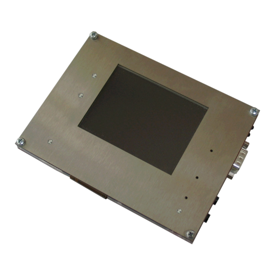
Summary of Contents for OLIMEX LPC2478-STK
- Page 1 LPC2478-STK and LPC2478-STK-MICTOR development boards User's Manual Document revision C, October 2012 Copyright(c) 2009, OLIMEX Ltd, All rights reserved Page 1...
- Page 2 Cables: You will need different cables depending on the used programming/debugging tool. If you use Olimex's ARM-JTAG, you will need a LPT cable. If you use ARM-USB-OCD or ARM- USB-TINY, you will need USB A-B cable. If you use a software...
- Page 3 programmer such as FlashMagic, you may need RS232 or other cables. Hardware: Programmer/Debugger – ARM-JTAG, ARM-USB-TINY or ARM- USB-OCD or other compatible programming/debugging tool. Software: The board comes pre-loaded with Uboot and the CD contains ucLinux image you can copy to USB flash disk and boot. You can use GCC or other commercial ARM compiler if you want to develop without ucLinux RTOS.
- Page 4 USB 2.0 full-speed dual-port device/host/OTG controller with on-chip PHY and associated DMA controller. Four UARTs with fractional baud rate generation, one with modem control I/O, one with IrDA support, all with FIFO. CAN controller with two channels. SPI controller. Two SSP controllers, with FIFO and multi-protocol capabilities. One is an alternate for the SPI port, sharing its interrupt.
- Page 5 On-chip power-on reset. On-chip crystal oscillator with an operating range of 1 MHz to 24 MHz. On-chip PLL allows CPU operation up to the maximum CPU rate without the need for a high frequency crystal. May be run from the main oscillator, the internal RC oscillator, or the RTC oscillator.
- Page 6 BLOCK DIAGRAM: Page 6...
- Page 7 MEMORY MAP: Page 7...
- Page 8 SCHEMATIC: 10u/6.3V -10V_E 220uF/10V/tnant 8.2k/1% 1.1K/1% 1N5819S 10u/6.3V 1.5n 100uF/25V/SMD 10u/6.3V 10u/6.3V GND1 GND2 GND3 GND4 GND5 CAN1_T 4.7K 4.7K VREF_E VDDC RST# TXER VDDPLL TXC/REFCLK REFCK TXEN TXEN TXD0 GND8 TXD1 GND7 TXD2 VDDTX TXD3 COL/RMII RMII CRS/RMII_BTB GND6 VDDRCV GND3 VDDIO2...
- Page 9 BOARD LAYOUT: POWER SUPPLY CIRCUIT: LPC-2478STK is powered by +(9-12)VDC/6VAC applied at the power jack. LPC-2478STK could also be powered by a battery (CR2032, Li, 3V) but this battery only powers the 2KB internal SRAM and the RTC (Real Time Clock). The consumption of LPC-2478STK varies depending on the supplied power but at +10VDC it is about 250mA.
- Page 10 JUMPER DESCRIPTION: CAN_D CAN Disable. If this jumper is closed, the CAN is disabled. Default state is open. CAN_T This jumper assures correct work of the CAN. At each end of the bus it should be closed. This means that if you have only two devices with CAN, the jumpers of both devices should be closed.
- Page 11 AOUT IrDA RX output pin jumper – opened if there is no IrDA module or it is disabled. Default state is opened if your board doesn't have an IrDA connector. This jumper, when closed, outputs the LCD[0] signal from the LPC2478 to the TFT display.
- Page 12 ETM_E If you put this jumper, you enable the MICTOR Trace connector. Default state is open. BDS_E Boundary scan enable. Default state is open. C/SC This jumper controls the USB device interface. If 1-2 are shorted, the USB is always enabled. If 2-3 are shorted, the USB Enable is controlled by the MCU LPC2478 signal USB1_CONNECT.
- Page 13 INPUT/OUTPUT: SD/MMC LED (red) with name SD connected to SD/MMC pin 4. Power-on LED (red) with name PWR – this LED shows that +3.3V is applied to the board. USB host LED (yellow) with name USB_H_LINK – connected to LPC2478 pin 147 (P1[13]/ENET_RX_DV).
- Page 14 EXTERNAL CONNECTORS DESCRIPTION: JTAG: Pin # Signal Name Pin # Signal Name +3.3V +3.3V TRSTN RTCK +5V_JLINK Input Test Data In. This is the serial data input for the shift register. OutputTest Data Out. This is the serial data output for the shift register.
- Page 15 RXD0 TXD0 ISP_E The RS232 in LPC2478-STK and LPC2478-STK is configured as DTE. Note that in order to establish connection to another DTE device (e.g. personal computer) you will need a null modem cable TXD0 OutputTransmit Data. This is the asynchronous serial data output (RS232) for the shift register on the UART controller.
- Page 16 CAN: Pin # Signal Name CANL CANH CANL and CANH are either deferential input, or differential output depending on the function of the MCP2551 CAN controller (receiving or transmitting data). Page 16...
- Page 17 PWR: Pin # Signal Name Power Input The power input should be +(9-12VDC)/6VAC. Audio In: Pin # Signal Name Input Microphone Input. This pin is input to the DSP codec VS1002D. Audio Out: Pin # Signal Name LEFT GBUF RIGHT LEFT OutputLeft channel output.
- Page 18 EXT: Pin # Signal Name Pin # Signal Name +3.3V P0[4]/I2SRX_CLK/LCD [0]/RD2/CAP2[0] P0[5]/I2SRX_WS/LC P0[6]/I2SRX_SDA/LCD D[1]/TD2/CAP2[1] [8]/SSEL1/MAT2[0] P0[7]/I2STX_CLK/L P0[8]/I2STX_WS/LCD[ CD[9]/SCK1/MAT2[1 16]/MISO1/MAT2[2] P0[9]/I2STX_SDA/L TXD3 CD[17]/MOSI1/MAT2 RXD3 P4[31]/#CS1 P4[30]/#CS0 P4[27]/BLS1 P4[26]/BLS0 P4[24]/#OE P4[17]/A17 P0[10]/TXD2/SDA2/MA T3[0] P0[11]/RXD2/SCL2/ MAT3[1] Page 18...
- Page 19 UEXT: Pin # Signal Name +3.3V TXD2 RXD2 SCL2 SDA2 MISO MOSI SSEL USB host: Pin # Signal Name USB_PWRD2 U2D- U2D+ USB_PWRD2 Output USB Power. This signal is output from the processor and input for the USB host. U2D-, U2D+ I/O This signals form the differential input/output depending on the direction of the data transfer.
- Page 20 VBUS OutputUSB device power. U1D-, U1D+ This signals form the differential input/output depending on the direction of the data transfer. LAN: Pin # Signal Name Chip Side Pin # Signal Name Chip Side LED100/DUP 2.5V LEDACT Color Usage Right Yellow Activity Left Green...


Need help?
Do you have a question about the LPC2478-STK and is the answer not in the manual?
Questions and answers