
Subscribe to Our Youtube Channel
Related Manuals for OLIMEX PIC32-MAXI-WEB


Summary of Contents for OLIMEX PIC32-MAXI-WEB
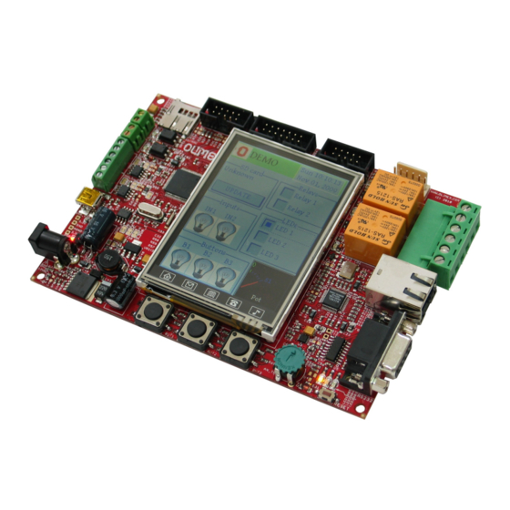
- Page 1 PIC32-MAXI-WEB General purpose development board USER’S MANUAL Document revision C, October 2015 Designed by OLIMEX Ltd, 2013 All boards produced by Olimex LTD are ROHS compliant...
-
Page 2: Disclaimer
This document is intended only to assist the reader in the use of the product. OLIMEX Ltd. shall not be liable for any loss or damage arising from the use of any information in this document or any error or omission in such information or any incorrect use of the product. -
Page 3: Table Of Contents
Table of Contents DISCLAIMER ......................2 1. INTRODUCTION ....................4 1.1 BOARD FEATURES ....................... 4 1.2 ELECTROSTATIC WARNING: .................... 4 1.3 BOARD USE REQUIREMENTS: ..................4 1.4 BOARD LAYOUT ........................5 2. MICROCONTROLLER DETAILS ..............6 2.1 FEATURES ..........................6 2.2 BLOCK DIAGRAM ........................ -
Page 4: Introduction
Dimensions (140×100) mm (5.51×3.94)" 1.2 ELECTROSTATIC WARNING: The PIC32-MAXI-WEB board is shipped in protective anti-static packaging. The board must not be subject to high electrostatic potentials. General practice for working with static sensitive devices should be applied when working with this board. -
Page 5: Board Layout
Hardware: The board requires +12V regulated power supply. !!! Please note that the PIC32 processor on this board is not supported by the once famous ICD2 programmer/debugger and derivatives. You would need a newer debugger/programmer. Please ensure your programmer/debugger is compatible with PIC32 microcontrollers. 1.4 BOARD LAYOUT Page 5 of 22... -
Page 6: Microcontroller Details
2. MICROCONTROLLER DETAILS Some of the details about the main microcontroller in PIC32-MAXI-WEB (PIC32MX795F512L) microcontroller are mentioned in this chapter. It is highly recommended to refer to the original datasheet which might be downloaded from the official Microchip web-side. 2.1 FEATURES... - Page 7 lines Hardware Real-Time Clock and Calendar (RTCC) Five 16-bit Timers/Counters (two 16-bit pairs combine to create two 32-bit timers) Five Capture inputs Five Compare/PWM outputs Five external interrupt pins High-speed I/O pins capable of toggling at up to 80 MHz ...
-
Page 8: Block Diagram
2.2 BLOCK DIAGRAM A block diagram with main functional parts of the microcontroller as seen in the official Microchip documentation. Page 8 of 22... -
Page 9: Memory Map
2.3 MEMORY MAP The microcontroller's memory regions as seen in the official Microchip documentation. Page 9 of 22... -
Page 10: Board Schematic And Dimensions
PIC32-MAXI-WEB. 3.1 SCHEMATIC The schematic of PIC32-MAXI-WEB is available for reference on the next page. Only the board schematic is available to the customer. It is available only as a stand-alone PDF document and as a reference image on. The board design files are kept private. - Page 11 PIC32-MAXI-WEB, board revision A: 2.5V UEXT1 3.3V RXD1_INT 3.3V 3.3V 4.7k 4.7k UEXT1 See LPC2378-STK_Rev.C SW_SCL1 0R(NA) 0R(NA) SW_SDA1 PHY_IRQ TXD1 RXD1 AETXEN 3.3V MOSI3A SCL1 SDA1 MISO3A MISO1 MOSI1 3.3V SCK1 UEXT1_CS 3.3V 100nF 10uF/6.3V/0805 FB0805/600R/200mA(201209-601) BH10S 100nF PHY_VDD_PLL PHY_RSTN 10uF/6.3V/0805...
-
Page 12: Physical Dimensions
3.2 PHYSICAL DIMENSIONS Note that all dimensions are in millimeters. Page 12 of 22... -
Page 13: Control Circuitry
LEDs on and established Ethernet connection. 4.2 RESET CIRCUIT PIC32-MAXI-WEB reset circuit is made of D4 (1N4148), RC group R55 – 10k and C31 – 100nF. Serial resistor R56 – 330Ω is used to prevent fast C31 charge and discharge when PIC32MX795F512L is being programmed. -
Page 14: Jumpers, Connectors And Interfaces
5. JUMPERS, CONNECTORS AND INTERFACES In this chapter you will find the description of the jumpers and what signals might be found on the different connectors. 5.1 JUMPER DESCRIPTION 3.3V_E – Enables 3.3V supply for PIC32MX795F512L and all other devices. Default state closed (shorted). -
Page 15: External Connector Description
350mA. The power jack is like the ones we use on all Olimex boards → YDJ-1134 (2mm in diameter front hole). If your power adapter doesn't have the same jack you would need to adapt it. -
Page 16: Rs232/Uart
Pin # Signal name RSTN 3.3V PGED2 PGEC2 PGED2 conducts I/O operations for the “Program Data” signal. Serial data for programming. PGEC2 serves only as input for the “Program Clock” signal. Clock used for transferring the serial data (output from ICSP, input for the MCU). 5.3.3 RS232/UART Pin # Signal name... -
Page 17: Can1 And Can2
5.3.5 ETHERNET Pin # Signal name(chip side) Pin # Signal name(chip side) Not Connected (NC) Not Connected (NC) VCC/2 (2.5V) Not Connected (NC) Color Usage Left Yellow 100MBits/s (Half/Full duplex) Right Green Activity 5.3.6 CAN1 AND CAN2 Controller Area Network(CAN) is a standard designed to allow microcontrollers and devices to communicate with each other within a vehicle without a host computer. -
Page 18: Uext1
5.3.8 UEXT1 The 10-pin UEXT connectors are typically mounted on Olimex boards. They pack three common interfaces in a single connector – UART, I2C and SPI. You can use the UEXT connector to access this interfaces easier (via jumper wires, for example). -
Page 19: Microsd Card
5.3.10 MICROSD CARD Pin # Signal name MCIDAT2 CS_MMC MOSI3A VDD (3.3 V) AC1TX/SCK3A MISO3A MCIDAT1 Not Connected Not Connected Not Connected Not Connected Page 19 of 22... -
Page 20: Available Demo Software
RTOS with excellent support and online documentation. Version used is v7.3.0. MPLAB has support for FreeRTOS (Tools/RTOS viewer). You could find demo software for PIC32-MAXI-WEB board at the board's web page. It is recommended to refer to the “README.txt” file inside the demo archive. -
Page 21: Revision And Ordering Information
How to purchase? You can purchase directly from our online shop or from any of our distributors. Note that usually it is faster and cheaper to purchase Olimex products from our distributors. List of confirmed Olimex LTD distributors and resellers: https://www.olimex.com/Distributors. -
Page 22: Warranty And Support
All goods are checked before they are sent out. In the unlikely event that goods are faulty, they must be returned, to OLIMEX at the address listed on your order invoice. OLIMEX will not accept goods that have clearly been used more than the amount needed to evaluate their functionality. - Page 23 Mouser Electronics Authorized Distributor Click to View Pricing, Inventory, Delivery & Lifecycle Information: Olimex Ltd. PIC32-MAXI-WEB...
Need help?
Do you have a question about the PIC32-MAXI-WEB and is the answer not in the manual?
Questions and answers