
Related Manuals for OLIMEX A13-OLinuXino


Summary of Contents for OLIMEX A13-OLinuXino
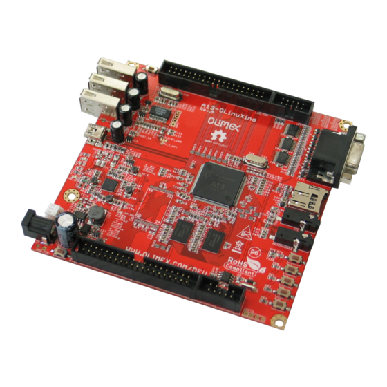
- Page 1 A13-OLinuXino and A13-OLinuXino-WIFI Open-source single-board Android 4.0 mini-computer USER’S MANUAL Revision G, October 2014 Designed by OLIMEX Ltd, 2012 All boards produced by Olimex LTD are ROHS compliant...
-
Page 2: Disclaimer
This document is intended only to assist the reader in the use of the product. OLIMEX Ltd. shall not be liable for any loss or damage arising from the use of any information in this document or any error or omission in such information or any incorrect use of the product. -
Page 3: Table Of Contents
2.7 GPIO under Debian ....................... 14 2.8 I2C and SPI under Debian ....................16 2.9 Software support ........................16 CHAPTER 3: A13-OLINUXINO BOARD DESCRIPTION ......... 17 3. Introduction to the chapter ..................... 17 3.1 Layout (top view) ........................17 CHAPTER 4: THE ALLWINNER A13 MICROCONTROLLER ....... 18 4. - Page 4 OLIMEX© 2014 A13-OLinuXino user's manual 6.1 Communication with the A13 ....................22 6.1.1 USB communication ............................. 22 6.1.2 UART1 interface ............................23 6.2 SD/MMC slot .......................... 24 6.3 UEXT module ......................... 25 6.4 GPIO-1 (General Purpose Input/Output) 10pin connector ..........26 6.5 GPIO-2 (General Purpose Input/Output) 40pin connector ..........
-
Page 5: Chapter 1: Overview
Thank you for choosing the OLinuXino single board computer from Olimex! This document provides a user’s guide for the Olimex OLinuXino board. As an overview, this chapter gives the scope of this document and lists the board’s features. The document’s organization is then detailed. -
Page 6: Target Market And Purpose Of The Board
There are three major processor variants. According to the names: A13-OLinuXino and A13- OLinuXino-MICRO and A13-SOM. The base model has also two flavors: A13-OLinuXino and A13-OLinuXino-WIFI. The first one is the base model that goes without any operating system image on board, while the second has two additional components –... - Page 7 OLIMEX© 2014 A13-OLinuXino user's manual – Chapter 6 covers the connector pinout, peripherals and jumper description – Chapter 7 provides the schematics – Chapter 8 contains the revision history, useful links and support information Page 7 of 37...
-
Page 8: Chapter 2: Setting Up The Olinuxino Board
- Wireless internet connectivity or USB modem – for browser access and access to the Android market Some of the suggested items can be purchased by Olimex, for instance: SY0612E – power supply adapter 12V/0.5A for A13-OLinuXino USB-SERIAL-CABLE-F – USB serial console cable female USB-MINI-CABLE –... -
Page 9: Powering The Board
Android image – configured for 480×800 screen resolution. 2.3 Powering the board There are three possible ways of powering A13-OLinuXino – via external supply using the power jack, via a battery using the battery connector or via the USB OTG connector. Depending on your preferred way of powering A13-OLinuXino you might need additional hardware. -
Page 10: Prebuilt Software
You can find and image with the view of the progress window in LiveSuit: Download links to all available images (and tools needed) can be found at the A13-OLinuXino wiki page: https://www.olimex.com/wiki/A13-OLinuXino. -
Page 11: Button Functions In Android
OLIMEX© 2014 A13-OLinuXino user's manual 2.5 Button functions in Android The following buttons represent functions in the Android: PWR_BUT – used to wake the board from stand-by HOME – shows the home screen; note that HOME is also used to enter bootloader mode for firmware update ENTER –... -
Page 12: Installing The Sdk Tools
Android 4.0 API 2.6.4. Connecting the A13-OLinuXino Power the A13-OLINUXINO. Now connect the miniUSB to the board and wait a bit for the USB to enumerate. After the tools are installed we navigate to “platform-tools” folder located in the directory of the tools (where we extracted in point 1), then we enter: ./adb devices... -
Page 13: Downloading The Default Config File And Script Tool
A13_config_600x800.fexbin /sdcard/nanda/script.bin 2.6.7. Restarting the A13-OLinuXino We go to the shell of the A13-OLinuXino board and reboot 2.7 GPIO under Debian You can read data from a given GPIO port. The logical ranges are usually as follows:... - Page 14 OLIMEX© 2014 A13-OLinuXino user's manual 2.4V-3.3V for HIGH (or 1) All voltages are measured against ground (GND). If the input signal is to high, you will at least destroy the port! The algorithms for writing a value to a GPIO port and reading such a value are pretty similar. The usage of GPIO ports follows the algorithm (we would use GPIO #49 for demonstration purposes): 1.
-
Page 15: I2C And Spi Under Debian
We usually try to provide details on how to build the Linux and the Android images at our wordpress page: http://olimex.wordpress.com/. Another useful place is the Olimex forums where a lot of people share their experience and advice: https://www.olimex.com/forum/ Additional Android and Linux support and features are added overtime. The Linux support is a work-in-progress and you should not expect full Linux support after the initial volume of such boards have become available on the market. -
Page 16: Chapter 3: A13-Olinuxino Board Description
3. Introduction to the chapter Here you get acquainted with the main parts of the board. Note the names used on the board might differ from the names used below to describe them. For the actual names check the A13-OLinuXino board itself. -
Page 17: Chapter 4: The Allwinner A13 Microcontroller
OLIMEX© 2014 A13-OLinuXino user's manual CHAPTER 4: THE ALLWINNER A13 MICROCONTROLLER 4. Introduction to the chapter In this chapter is located the information about the heart of OLinuXino – its microcontroller. The information is a modified version of the datasheet provided by its manufacturers. - Page 18 OLIMEX© 2014 A13-OLinuXino user's manual R-TP Controller 4-wire resistive TP interface 2 points and gesture detection Boot Devices NAND Flash SPI Nor Flash SD Card USB Powerful Acceleration Graphic (3D, Mali400 MP) ...
-
Page 19: Block Diagram
OLIMEX© 2014 A13-OLinuXino user's manual 4.2 Block diagram The block diagram is taken from Allwinner's datasheet. Page 19 of 37... -
Page 20: Chapter 5: Control Circuity
The power supply is handled mainly by AXP209 power management system, an Allwinner chip that goes together with the A13 processor. The power supply circuit of A13-OLinuXino allows flexible input supply from 6V to 16V. The minimum amperage suggested is 1A, and this threshold would rise if using all the three USB-HOSTs, a lot of GPIOs and LCD_con. -
Page 21: Chapter 6: Connectors And Pinout
UART1 interface allowing you to connect to an USB port. 6.1.1 USB communication The main way of communicating with the firmware of A13-OLinuXino is via the USB-OTG connector. You will also need a software tool “LiveSuit” and a newer firmware image if you wish to upgrade the firmware. -
Page 22: Uart1 Interface
Processor Pin # 3.3V SDC0_SCK SDC0_DATA3 Consider the above table when connecting the USB-SERIAL-CABLE-F according to the wire color code. If having A13-OLinuXino with 1xUART0 and the table with the signals can be found below: UART0 UART1 Pin # Signal Name... -
Page 23: Sd/Mmc Slot
The microSD card slot is a standard 8pin connector. The SD card can be used for booting the operating system for A13-OLinuXino. It is suggested to have an SD card with a proper Linux/Android image especially if you have ordered a version of the board without NAND memory. -
Page 24: Uext Module
OLIMEX© 2014 A13-OLinuXino user's manual 6.3 UEXT module A13-OLinuXino has an UEXT connector and can connect with Olimex's UEXT modules. For more information on UEXT please visit: https://www.olimex.com/Products/Modules/UEXT/resources/UEXT.pdf UEXT connector Pin # Signal Name Processor Pin # 3.3V UART1_TX UART1_RX... -
Page 25: Gpio-1 (General Purpose Input/Output) 10Pin Connector
OLIMEX© 2014 A13-OLinuXino user's manual 6.4 GPIO-1 (General Purpose Input/Output) 10pin connector The GPIO connector numbers are printed at the bottom of the board for your convenience. GPIO-1 Pin # Signal Name Processor Pin # 1 5V 2 GND 3 3.3V... -
Page 26: Gpio-2 (General Purpose Input/Output) 40Pin Connector
OLIMEX© 2014 A13-OLinuXino user's manual 6.5 GPIO-2 (General Purpose Input/Output) 40pin connector The GPIO pins are led out on a separate 40pin connecter. They allow the user to attach additional hardware, check readings or perform hardware debug. The GPIO-2 connector numbers are printed at the bottom of the board for your convenience. -
Page 27: Lcd_Con 40Pin Connector
OLIMEX© 2014 A13-OLinuXino user's manual 6.6 LCD_CON 40pin connector The LCD_CON pins are led out on a separate 40pin connecter for the ease of connecting an LCD. We have tested the ability of the board to interact with such a display. They allow the user to attach additional hardware, check readings or perform hardware debug. -
Page 28: Pwr Jack
OLIMEX© 2014 A13-OLinuXino user's manual 6.7 PWR Jack The power jack used is the typical 2.5mm one used by Olimex in most of our products. You should provide between 6 and 16 volts @ 1.5A maximum to the board. Pin #... -
Page 29: Battery Connector
OLIMEX© 2014 A13-OLinuXino user's manual 6.9 Battery connector When using the battery connector keep in mind that it is an energy solution that wouldn't be able to power the board and all the peripherals. The voltage of a 3.7V LIPO battery would be enough to power the processor and the memory but won't be enough to power external touchscreen LCD. -
Page 30: Jumper Description
OLIMEX© 2014 A13-OLinuXino user's manual 6.8 Jumper description Please note that all the jumpers on the board are SMD type. If you feel insecure of your soldering/cutting technique it is better not to try to adjust the jumpers. The only really important jumper on the board is CE_NAND_E, which needs to be closed if you have board variant with NAND flash memory but you wish to boot OS from SD card. - Page 31 OLIMEX© 2014 A13-OLinuXino user's manual 2×2Gb (512M x 8 bit) DDR3 SDRAM – the exact memory used in the first revisions of the board is hynix H5TQ2G83CFR-H9C 1×32Gb (4096M x 8 bit) NAND FLASH – the exact memory is hynix H27UBG8BTR – only present in A13-OLinuXino-WIFI LED1 + CHLED + PWR_LED –...
-
Page 32: Chapter 7: Schematics
If you are looking for a schematic of an older revision of the board and it isn't available at our web site you may request it by the support e-mail. Note that A13-OLinuXino-WIFI has all the components shown in the schematics. The stripped down version (A13-OLinuXino, without the -WIFI part) lacks two components: the NAND memory and the embedded WIFI module RTL8188CU. -
Page 33: Physical Dimensions
OLIMEX© 2014 A13-OLinuXino user's manual 7.2 Physical dimensions Note that all dimensions are in mils. The three highest elements on the board in order from the tallest to the shortest are: capacitor C126 – 650mils, the three USB hosts – 500mils, the VGA connector - 475mils... -
Page 34: Chapter 8: Revision History And Support
OLIMEX© 2014 A13-OLinuXino user's manual CHAPTER 8: REVISION HISTORY AND SUPPORT 8. Introduction to the chapter In this chapter you will find the current and the previous version of the document you are reading. Also the web-page for your device is listed. Be sure to check it after a purchase for the latest available updates and examples. -
Page 35: Board Revision
1. Added BAT54C after Rx to UART1 connector 2. Added 4.32k pull-up resistor on the RX line 3. Changed wrong prints of the revision and the Olimex web-site 4. Some libraries updated and some component prints removed due to space restrictions 5. -
Page 36: Useful Web Links And Purchase Codes
A13-OLinuXino-WIFI – the full version of A13-OLinuXino with added NAND memory (Android image) and MOD-WIFI_RTL8188 A13-OLinuXino – the lite version of A13-OLinuXino with no external NAND and no embedded internet interface USB-SERIAL-CABLE-F – USB serial console cable for connecting to UART1 SY0612E –... -
Page 37: Product Support
All goods are checked before they are sent out. In the unlikely event that goods are faulty, they must be returned, to OLIMEX at the address listed on your order invoice. OLIMEX will not accept goods that have clearly been used more than the amount needed to evaluate their functionality.
Need help?
Do you have a question about the A13-OLinuXino and is the answer not in the manual?
Questions and answers