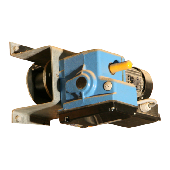
Summary of Contents for Munters IA0090
- Page 1 IA Inlet Actuator Instruction Manual IA Inlet Actuator Models: IA0090 • IA0090P • IA0250D • IA0250DP © Munters Corporation, April 2019 QM1235r2...
-
Page 2: Warranty
• Available as 1-phase 115 V (60 Hz) electric motor with UL and CSA approval. Please Note: To achieve maximum performance and insure long life from your Munters product it is essential that it be installed and maintained properly. Please read all instructions carefully before beginning installation. - Page 3 Connection and operation - abbreviations Connecting the control components: switch materials and cable lengths Overview: connections and elements for “Operating & Setting” Rotational directions and end positions IA0090 motor gearbox Wiring diagrams IA0090 motor gearbox Setting the limit switch system...
-
Page 4: About The Equipment
1.2 Configurations IA0090/IA0250D Motor Gearbox The IA0090/IA0250D ships in 2 boxes, Box 1 of 2 is the Gear Motor and Box 2 of 2 is the installation kit. • The IA0090/IA0250D is standard delivered with a 1-phase motor: A - 115V •... - Page 5 1.3 Options for IA0090 Motor Gearbox Potentiometer: Position feedback IA0090P An optional potentiometer built-in set (AC1429) for the IA0090 motor gearbox. Position feedback which works in combination with the limit switch system. The built-in set with potentiometer makes it possible to signal with precision to a (climate) computer, not just the start and end positions of the limit switch system, but also all the intermediate positions of the driven system.
-
Page 6: Installation Instructions
IA0090 forces applied. *Please observe the following allowed mounting positions when installing the IA0090 Motor Gearbox Image 2.1 Use the M10 bolt and washer from the mounting kit to mount the plates to the gearbox. - Page 7 Chapter 2 Installation Instructions Mounting IA0090/IA0250D: Belt Drum - Ceiling Mount (Configuration 1) Mount the square mounting plate to the IA0090 by choosing option 1 (side) or 2 (foot). IA0090, ACTUATOR MOUNTING BRACKET M10 SPLITLOCK WASHER M10x20 BOLT Configuration 1 2.2 Mounting the Drum, Winch Belt and Couplings...
- Page 8 Installation Instructions 2.3 Pre-winding the Winch Belt onto the Belt Drum To safely use the belt drum and winch belt of the IA0090/IA0250D it is necessary to pre-wind the belt at least ½ a revolution onto the drum. Belt drum with single or double belt: •...
- Page 9 The overview in image 3.3.2 shows the most important connections, parts and elements for operating and setting a IA0090 motor gearbox. As shown in image 3.3.1, remove the limit switch cover of the gearbox. : Cover in image 3.3.2 is also removed for a complete overview. However it is not necessary to remove cover in this manual.
- Page 10 Unscrew the four bolts and remove the limit switch cover while the gasket stays in place. 1. Limit switch cover 2. Gasket 3. Bolts 4. Cover electric motor Image 3.3.1 The overview of a IA0090 motor gearbox. The detailed diagrams for connecting are shown in Step 3.5 Image 3.3.2 © Munters Corporation, April 2019 QM1235r2...
- Page 11 Clockwise [CCW] (B) which is away from the motor. Also visible are the corresponding limit switches for setting the end positions A and B. See figure below. Based on where the IA0090 and inlets are mounted and the direction the belt is wrapped on the drum, determine which direction will be open and which will be close.
- Page 12 The image and the diagram below show the connections of a Temporary Power Cable. Image 3.5.1 IA0090 Image 3.5.2 ● Go to Step 3.6 and set the Limit Switch System prior to the permanent connections. ● Remove the Temporary Power Cable. © Munters Corporation, April 2019 QM1235r2...
- Page 13 Chapter 3 Connection and Operations Make the permanent connections. ● The image and the diagram below show the permanent connections of the IA0090 gearbox. GROUND CW (Clockwise) CCW (Counter Clockwise) NEUTRAL Image 3.5.3 Diagram 3.5.4 * Suitable for inductive load of 115V - 2,5 A...
- Page 14 4. Now turn the Adjusting Ring over the Textured Brass Nut so far, that the working switch is just contacted by the long Adjusting Screw. 5. Now tighten the Set Screws firmly on the Textured Brass Nut. The Adjusting Ring cannot turn on the Brass Nut anymore. The Limits are now set. © Munters Corporation, April 2019 QM1235r2...
- Page 15 ① still in place, and mount it with the four bolts. See image 3.3.1. : If the feedback option is applicable, then first install and set the potentiometer (P) according to Step 3.4 and Step 3.5. © Munters Corporation, April 2019 QM1235r2...
- Page 16 For a 2m belt use gear ?? on the ??? shaft. with Gear For a 3m belt use gear ?? on the ??? shaft. Gear on IA Shaft Figure A Terminal Block K2 Figure B © Munters Corporation, April 2019 QM1235r2...
- Page 17 The table below can be used to select the necessary gearwheels when fitting a potentiometer and installation set in an IA0090 motor gearbox. The table shows the maximum number of revolutions of the drive shaft of the IA0090 motor gearbox.
-
Page 18: Maintenance
IA Actuator by Munters Corporation, Lansing, Michigan U.S.A. 1-800-227-2376 Munters Europe AB, Isafjordsgatan 1, P.O. Box 1150, SE-164 26 Kista, Sweden. Phone +46 08 626 63 00, Fax +46 8 754 56 66. Munters Corporation 2691 Ena Drive Lansing, MI 48917 U.S.A. Phone +1 800-227-2376, Fax +1 517-676-7078 www.munters.us...


Need help?
Do you have a question about the IA0090 and is the answer not in the manual?
Questions and answers