Sign In
Upload
Manuals
Brands
Fireye Manuals
Control Unit
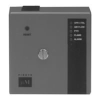
MicroM MEC320C
User Manuals: Fireye MicroM MEC320C Safeguard Control
Manuals and User Guides for Fireye MicroM MEC320C Safeguard Control. We have
1
Fireye MicroM MEC320C Safeguard Control manual available for free PDF download: Manual
Fireye MicroM MEC320C Manual (59 pages)
FLAME SAFEGUARD CONTROLS
Brand:
Fireye
| Category:
Control Unit
| Size: 1 MB
Table of Contents
Description
1
Specifications
2
Ambient Temperature Limits
2
Load Ratings
3
Alternative Load Ratings
3
Composition of each Combination
3
All Dimensions in Inches (Millimeters in Parentheses)
4
Approvals
5
Ordering Information
6
Microm Chassis Types
6
Microm Programmer Models
6
Accessories
8
Flame Scanners
8
Installation of Control, Scanners and Flame Detectors
9
Wiring Base
9
Installing the Programmer and Amplifier Modules
10
Amplifier
10
Programmer
10
Replaceable Fuse
10
Programmer Dipswitch Settings
11
Microm Programmer Dip Switch Configuration
11
Dipswitch Definitions
12
Led Indicator Lights
12
Lockout Codes
13
Ptfi:
13
Flame
13
Diagnostic Messages - Troubleshooting Guide
14
Programmer Description
14
MEP100 and MEP101
14
Pilot Ignited Burners
14
Safety Shutdown
15
Direct Spark Ignited Burners
15
Normal Operation
15
Mep102 & Mep104
15
Timing Chart
16
Mep200 Series
16
Mep100P
16
MEP100 as FLAME SWITCH
16
Timing Charts
17
Mep235
17
Mep236
17
Mep500 Series
18
Type Mep236
18
Type Mep230H
18
Type Mep560
19
Type Mep561
19
Mep300/Mep600 Series
20
Type Mep562
20
Type Mep300
20
Type Mep304
21
Type Mep335
21
Type Mep397
22
Type Mep696
22
Optional Plug-In Boards
23
Type Mep697
23
Plug -In Board Location and Installation
23
Function
24
Remote Reset
24
Advanced Reset Functions
24
Smart Reset
24
Remote Display
25
Smart Recycle
25
Address Mode
25
Operating Status
26
Additional Information on Operating Status
26
Timing
26
Lockout History
27
Program Setup
27
System Info
28
Communications
28
Inputs
30
Outputs
30
Logic Dispatch
31
Logic Dispatcher
31
Program Module Identification
32
Message Description
33
Addressing Modes
33
Test Jack Voltage
34
Amplifier Test Jack Voltage Vs. Ed510 Display Board
34
External Meter Connections
35
Installation Testing
35
New Warning for Micro-M Control Product Bulletin
35
Use of Test Meter (All Controls)
35
Normal Pilot Flame Test (Programmers with Run/Check Switch)
36
Minimum Pilot Test
36
Flame Failure Test
36
Service Guide
38
Wiring Arrangements
40
Suggested Grounding Rules
46
Installation
46
Maintenance
47
Installation - Uv Scanners
47
Typical Scanner Installations
48
Scanner Must Have Unobstructed
48
Flame Must Completely Cover
48
Operation — 45Uv5 Self-Checking Uv Scanner
49
Wiring - Uv Scanners
49
Installation—Infrared Scanner Type 48Pt2
50
Wiring
50
Keeping the Scanner Cool
50
INSTALLATION - 69Ndl FLAME ROD
51
Type 69ND1 Flame Rod
52
Flame Signal Strength
52
Contacts
52
Humidity
52
Mounting 45UV5 Scanner
53
UV8A Scanner
53
Mounting for High Temp. Applications
53
Alternate Standard Mounting
53
Mounting UV1A/UV1B Scanners
54
Standard Mounting
54
Mounting with Heat Insulating Nipple
54
Standard Mounting with Purging/Cooling Air
54
M-Series to M-Series II to Microm Cross Reference Listing
55
Red Jumper Wire
56
Advertisement
Advertisement
Related Products
Fireye MicroM MEC320
Fireye MicroM MEC320R
Fireye MicroM MEC320D
Fireye MicroM MEC320RD
Fireye MicroM MEC320RC
Fireye MicroM MEC320TS
Fireye MicroM MEC120
Fireye MicroM MEC120D
Fireye MicroM MEC120RC
Fireye MicroM MEC230RC
Fireye Categories
Controller
Control Unit
Control Systems
Scanner
Industrial Equipment
More Fireye Manuals
Login
Sign In
OR
Sign in with Facebook
Sign in with Google
Upload manual
Upload from disk
Upload from URL