Table of Contents
Advertisement
Quick Links
WARNING: Selection of this control for a particular application should be made by a com-
petent professional, licensed by a state or other government. Inappropriate application of this
product could result in an unsafe condition hazardous to life and property.
DESCRIPTION
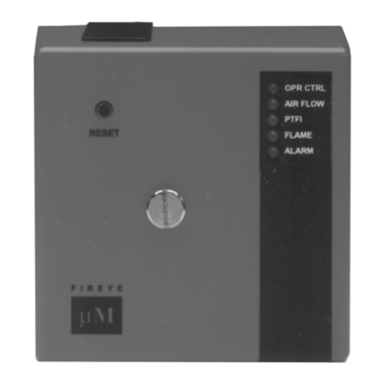
The Fireye MicroM Series Flame Safeguard Control is a compact, microprocessor based,
modular burner management system designed to provide automatic ignition and continuous
flame monitoring for commercial sizes of heating and process equipment firing any type of
fuel. The advantages of the MicroM are zero dependence on discrete components previ-
ously used for timing functions thereby extending the stability of the system and reducing
the effects of time and temperature.
A complete MicroM system consists of the relay module, MEC320TS, programmer mod-
ule, MEP696, amplifier module, MEUV4, subbase, 61-3060 or 61-5042 and UV scanner,
UV1A3 or UV1A6. An optional alphanumeric display (ED510) is available that provides
complete English language description of the current operating status as well as diagnostic
history.
To maximize safety the MEP696 provides early spark termination followed by a pilot prov-
ing period. This prevents the unwanted detection of spark generated by a maladjusted pilot
and spark assembly. The air flow switch connected between terminals 7 and 6 must be
closed within 10 seconds after the start of a cycle. Below is a detailed list of the MEP696
operating parameters.
Functions provided on the MEC320TS chassis and MEP696 programmer:
Fixed 30 second pre-purge period
1.
Ignition terminal 4 shuts off 10 seconds into the Pilot Trial for Ignition
2.
5 second Pilot Proving period
3.
Pilot terminal 3 shuts off 5 seconds into the Main Trial for Ignition
4.
Post Purge has selectable 0 or 60 seconds duration
5.
Release to modulate contacts 1 second after AUTO
6.
Lockout occurs if air flow, terminal 6, is not proven 10 seconds into purge
7.
Modbus communications allowing for hookup to plc system
8.
Dip-switch selectable communication baud rate, 4800, 9600 or 19200 baud
9.
Dip-switch selectable pilot trial for ignition timing, 5 or 10 seconds
10.
Smart LEDs that provide on board diagnostic lockout information
11.
Amplifier test jacks provide uniform 0-10 vdc for flame signal strength
12.
MicroM
FLAME SAFEGUARD CONTROLS
MEC320TS, MEP696, MEUV4
MC-3200
JUNE 6, 2006
FIREYE
APPROVED
1
Advertisement
Table of Contents

Subscribe to Our Youtube Channel
Related Manuals for Fireye MicroM Series


Summary of Contents for Fireye MicroM Series
- Page 1 DESCRIPTION The Fireye MicroM Series Flame Safeguard Control is a compact, microprocessor based, modular burner management system designed to provide automatic ignition and continuous flame monitoring for commercial sizes of heating and process equipment firing any type of fuel.
-
Page 2: Specifications
SPECIFICATIONS Supply: 120 VAC (min. 102, max. 132) 50/60 Hz. Power Consumption: 12 VA (Operating) Shipping Weight (Approx): 3 lbs (1.4 kg) AMBIENT TEMPERATURE LIMITS Table 1: MAXIMUM MINIMUM Control 140 F 60 C - 40 F - 40 C Scanner UV1A, UV2, 200 F 93 C... - Page 3 DIMENSIONS MOUNTING BASE 3/16” DIA. MOUNTING HOLES (4) KNOCKOUTS (12) FOR 1/2” CONDUIT 5 3/16” 4” 3/16” MOUNTING 1/2” HOLES 5 3/16” 5 5/16” 4” 1/2”’ 13/16” HEX 2 3/8” 2” 1” DIA ”L” (20.6) (60.3) (50.8) (25.4) 1 3/16” (30) 15/16”...
-
Page 4: Ordering Information
Use moisture resistant wire suitable for at least 90 degrees C. Good electrical wir- ing practice should be followed to ensure an adequate ground system. Refer to Fireye Service Note SN-100 separately and General Grounding Rules later in this document for grounding methods. - Page 5 FIGURE 1. WIRING ARRANGEMENT FOR PILOT IGNITED BURNERS USING MEP696 PROGRAMMER AIR FLOW OPERATING INTERLOCK CONTROL FLAME SCANNER FLAME ONLY (WATCHDOG) FLAME AMPLIFIER 120VAC MODULATE CONTACTS LOCATED ON 50/60Hz DAUGHTER BOARD PILOT VALVE SPARK MAIN FUEL VALVE ALARM BLOWER MOTOR IGNITION CONTACTOR INSTALLING THE PROGRAMMER AND AMPLIFIER MODULES...
- Page 6 Fuse. The fuse can blow as a result of an overload condition on Terminals 3, 4, or 5. To replace the fuse, remove power from the system and using a small screwdriver or similar tool, install a Fireye replacement fuse (P/N 23-197) or equivalent 10 amp fuse (e.g. Wick- man # 19373-071-K).
-
Page 7: Led Indicator Lights
optional ED510 display. Refer to the section using the optional ED510 display for detailed information. The ED510 display operates at 4800 baud only. To use the ED510 display, power must be removed and dip switches 1 & 2 must be set in the CLOSED position. SWITCHES INDICATORS (shown in closed or OFF position) -
Page 8: Lockout Codes
Alarm: This LED flashes when an alarm condition is detected and is also used as an address indicator (see communication). During an alarm condition, the Alarm LED is made to flash at approximately a 1 second rate. The remaining four LEDs are illuminated as a coded sequence identifying the reason for the lockout. - Page 9 DIAGNOSTIC MESSAGES - TROUBLESHOOTING GUIDE POSSIBLE CAUSE SOLUTION Check Programmer Voltage on Terminal 5 at improper time. Inspect wiring to main fuel valve Welded watchdog relay Replace chassis Internal diagnostic failure Replace programmer Check Chassis Voltage on Terminal 3 or 4 at improper time. Inspect wiring to pilot valve and igniter.
- Page 10 SEQUENCE TIMING MEP696 Timing Sequence Table 4: COMMUNICATIONS The protocol to be used is Modbus RTU. This is implemented by the master (PC, PLC, etc.) issuing a poll to the slave (MicroM) and the slave responding with the appropriate message. A typical format of a poll request is as follows: DST refers to the logical address of the slave set but using reset pushbutton or ED510.
- Page 11 Below is a table of currently available messages provided by the MicroM programmers, followed by a description where necessary. MESSAGE WORDS RESPONSE VALUE ADDRESS REQUESTED STATUS 83 (053H) = RUN; 202 (0CAH) = LOCKOUT MSGN Current message being displayed (see Table 3) GSTAT Defines Timer Type TIMER...
- Page 12 The MSGN being transmitted is a numerical value and must be interpreted by the communicating device, which actually is an advantage since this can be made to be whatever message text the end user wants. In other words, it allows for programming custom messages without actually changing the message in the programmer.
- Page 13 Table 1: Logic Dispatch LOGIC DISPATCHER VALUE MicroM MPOSTIDLE MPREPURGE1 MPURGE MTFI MSTABLE MTFMF MAUTO MSHTDWN1 MSHTDWN2 MIDLE...
- Page 14 Table 2: Message Description MicroM Message L1-7 OPEN FALSE FLAME STARTING BURNER INTRLCK OPEN LOCKOUT LINE FREQUENCY NOISE DETECTED LOCKOUT FLAME FAIL - PTFI UNIT ADDRESS MTFI IGNITION TIMING FLAME SIGNAL CYCLE COMPLETE LOCKOUT AMPLIFIER HIGH COUNT FAIL LOCKOUT FLAME FAIL – MTFI LOCKOUT FALSE FLAME –...
- Page 15 address after 31 is 0. The second method is to use the local reset located on the plug-in board. It is first necessary to open the operating control (L1-7) to have the MicroM in the IDLE or STANDBY position. Depressing the reset switch for greater than 10 seconds will cause the address of the MicroM to be displayed in a binary format on the LEDs located on the programmer board.
- Page 16 Fireye shall be limited exclusively to the right to replacement or repair as above provided. In no event shall Fireye be liable for consequential or special damages of any nature that may arise in connection with such product or part.
Need help?
Do you have a question about the MicroM Series and is the answer not in the manual?
Questions and answers