
Related Manuals for Okofen PELLEMATIC SmartXS

Summary of Contents for Okofen PELLEMATIC SmartXS
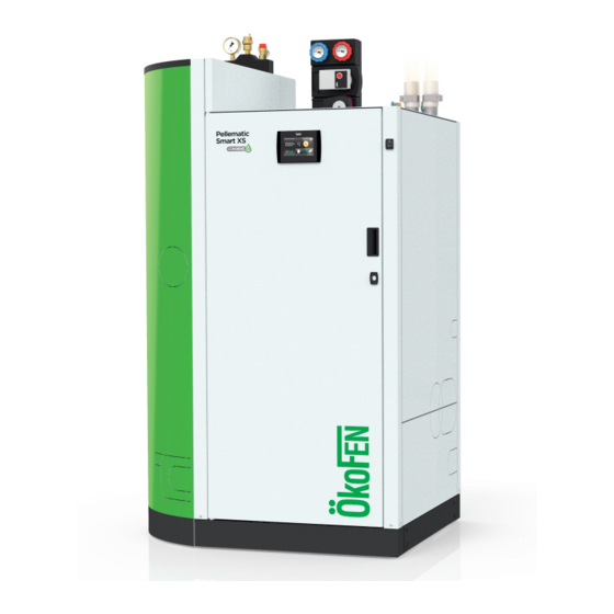
- Page 1 Please read carefully prior to installing and servicing. SAVE THESE INSTRUCTIONS Installation Manual PELLEMATIC® SmartXS FA — V2.09 Pelletronic TOUCH PE 607 USA_FA 2.1 · www.oekofen.com...
- Page 2 Title: Installation Manual PELLEMATIC® SmartXS Article number: PE 607 USA_FA 2.1 Version valid from: 07/2018 Approved: Wohlinger Christian Author & Manufacturer MAINE ENERGY SYSTEMS LLC 8 Airport Road — P.O. Box 547 Bethel Maine 04217 © MAINE ENERGY SYSTEMS LLC E-Mail: info@maineenergysystems.com www.maineenergysystems.com Subject to modifcations...
-
Page 3: Table Of Contents
Contents 1 Dear Customer ..............................5 2 Use only for the purpose intended ........................ 6 3 General information ............................7 4 Types of safety warning sign......................... 9 5 Warnings and safety instructions .........................10 5.1 Basic safety instructions ..........................10 5.2 Warning signs.............................. 10 5.3 What to do in an emergency........................ - Page 4 15.2 Fault texts..............................70 15.3 Malfunction report............................71 16 Default values and settings ........................86 17 Parts list ............................... 89 17.1 Pellematic SmartXS............................ 89 18 Technical data PELLEMATIC SmartXS....................... 93 19 Pellet boiler cautionary markings ......................95 Installation Manual PELLEMATIC® SmartXS...
-
Page 5: Dear Customer
Dear Customer Dear Customer Maine Energy Systems specializes in wood pellet heating. Our company enjoys an exclusive license from ÖkoFEN to manufacture products here in North America. We represent expertise, innovation and quality. We are delighted that you have decided to purchase our product. •... -
Page 6: Use Only For The Purpose Intended
Use only for the purpose intended Use only for the purpose intended The pellet boiler is designed to heat water for central or other indirect heating systems and hot water supply for buildings. It is not permissible to use the pellet boiler for any other purpose. Reasonable foreseeable inadvertent uses for the pellet boiler are not known. -
Page 7: General Information
General information General information As require by the United States Departmen of Environmental Protection the following information is given for the: Smart XS wood pellet fired central heating boiler. Manufactured by Maine Energy Systems, of 8 Airport Road, Bethel, Maine, 04217 •... - Page 8 General information The amount of draft in your chimney depends on the length of the chimney, local geography, nearby obstructions and other factors. Too much draft may cause excessive temperatures in the appliance and may damage the catalytic combustor. Inadequate draft may cause backpuffing into the room and ‘plugging’ of the chimney Inadequate draft will cause the appliance to leak smoke into the room through appliance and chimney connector joints an uncontrollable burn or excessive temperature indicates excessive draft.
-
Page 9: Types Of Safety Warning Sign
Types of safety warning sign Types of safety warning sign The warning signs use the following symbols and text. Types of safety warning sign Risk of injury Consequences of risk Avoiding risk 1. Risk of injury: Danger - indicates a situation that could lead to death or life- threatning injury. -
Page 10: Warnings And Safety Instructions
Warnings and safety instructions Warnings and safety instructions Observing safety instructions ensures that the heating system is operated safely. 5.1 Basic safety instructions • Never get yourself into danger; give your own safety top priority. • Keep children away from the central heating room and storage room. •... - Page 11 Warning signs R R i i s s k k o o f f f f i i r r e e Do not store any flammable materials in the boiler room. Do not hang out any washing in the boiler room. Do not operate with fuel loading or ash removal doors open.
-
Page 12: What To Do In An Emergency
What to do in an emergency 5.3 What to do in an emergency R R i i s s k k t t o o l l i i f f e e Never get yourself into danger; give your own safety top priority. - Page 13 Installation with an existing boiler P P o o s s s s i i b b l l e e e e s s c c a a p p e e o o f f f f l l u u e e g g a a s s : : Do not connect this unit to a chimney flue serving an- other appliance unless multiple appliances into a single flue is authorized by all authorities having jurisdiction.
-
Page 14: Prerequisites For Installing A Pellet Boiler
Prerequisites for installing a pellet boiler Prerequisites for installing a pellet boiler The following must be fulfilled before the installation and operation of a fully automatic pellet boiler. 6.1 Guidelines and standards for installing a pellet boiler Overview of standards and guidelines applying to the installation of a pellet boiler. Check whether you need to obtain planning permission or approval from the authorities for installing a new heating system or changing your existing system. -
Page 15: Flue Gas System
Flue gas system before water enters the boiler room. All components that come into contact with water must be replaced before the pellet boiler is put into operation again. 6.3 Flue gas system The flue gas system consists of the chimney and flue gas tube. The connection between pellet boiler and chimney is the flue gas tube. - Page 16 Flue gas system The condensation temperature of glue gas of wooden pellets (max. 10% water-content) is on average 122° F. 4. Chimney draft effect By reference of a chimney calculation according to EN 13 384-1, the diameter of the chimney has to be chosen and the system has to be checked for enough chimney draft.
-
Page 17: Safety Systems
Safety systems 6.4 Safety systems The following safety measures are the prerequisite for safe operation of your system. Emergency stop switch Every heating system must be able to be switched off with an Emergency Stop switch. The Emergency Stop switch location is determined by your local code requirement. It should remove all electrical power from the boiler. -
Page 18: Product Description
Product description Product description The description of the product is intended to provide an overview of the components that make up a MESys pellet heating system, the parts of the pellet boiler and advice on where you can find more information. 7.1 Function description The PELLEMATIC Smart XS heating system combines water heating and hot water storage. - Page 19 Function description Air Out & possible location Vacuum turbine Ash bin for Pressure Relief Valve Supply and Return Delivery auger Drain valve Air hose Flame return gate Optional Solar Coil Burner Pellet hose (suction Cleaning system system) Heat insulation Burner plate Storage tank Combustion chamber door Installation Manual PELLEMATIC®...
-
Page 20: Pellet Suction System
Pellet suction system 7.2 Pellet suction system The pellet suction system consists of the pellet hose, air hose and a suction turbine. The suction vacuum turbi- ne in the hopper conveys pellets in the pellet line from the storage room or fabric tank to the hopper. Key components of pellet suction system Pellet- Suction hose Line from the storage room auger or fabric tank to the hopper. - Page 21 Assembly of the vacuum system • Fire protection: At each wall penetration of the pellet hose, be sure to comply with local building code regulations. • Crossing: Please make sure that you cross the hoses as few times as possible. •...
- Page 22 Assembly of the vacuum system Connection of the pellet and air hose to the suction turbine PE 607 USA_FA 2.1...
-
Page 23: Storage Systems
Storage systems Storage systems There are two methods for storing pellets: in a storage room with an auger feed system (version A) or in a FleXILO fabric tank (version B). FleXILO fabric tanks can be located inside the central heating room, storage room or protected from wet and sun outside. -
Page 24: Bringing The Pellet Boiler Into The Boiler Room
Bringing the pellet boiler into the boiler room Bringing the pellet boiler into the boiler room This section describes the prerequisites as well as the working sequence required. Transport 2. Notes on bringing the unit into the building 3. Casing parts 4. - Page 25 Notes on bringing the unit into the building In order to reduce weight to 646 Lbs. burner and hopper may also be dismantled. Note: To install the heating system properly and ensure economical operation, operation, minimum clearance dimensions indicated below must be observed and followed when setting up the boiler. In addition, make sure that legislation in your country is complied with relating to the minimum clearance of the flue gas tube.
-
Page 26: Casing Parts
Casing parts 9.3 Casing parts The boiler is protected by a casing on all sides. The casing parts prevent contact with hot, moving and live components. They also give MESys pellet boilers a unique appearance. Burner housing Accumulator side section, short, top Accumulator side section, long Accumulator housing rear panel Pump group housing... -
Page 27: Dismantling For Transport To The Installation Location
Dismantling for transport to the installation location 1 1 0 0 Dismantling for transport to the installation location Dismantling of the Pellematic Smart XS down to the basic element is described below. Observe the dismantling instructions and sequence. Dismantle the Pellematic Smart XS according to the conditions at the installation location so that practicable and safe transport is possible. - Page 28 Dismantling of the housing parts Dismantling sequence of the housing parts: PE 607 USA_FA 2.1...
- Page 29 Dismantling of the housing parts Installation Manual PELLEMATIC® SmartXS...
- Page 30 Dismantling of the housing parts PE 607 USA_FA 2.1...
-
Page 31: Disconnection Of The Cable Routing
Disconnection of the cable routing 10.2 Disconnection of the cable routing The cable routing is divided into three main groups: Cable connection Disconnection Time of disconnection Cables to operating The operating device and boiler controller form No dismantling device part of the accumulator front panel. They are necessary! removed together. -
Page 32: Dismantling Of The Fresh Water Installation (Optional)
Dismantling of the fresh water installation (optional) 10.4 Dismantling of the fresh water installation (optional) L L e e a a k k s s All hydraulic connections must be properly tightened and newly sealed during installation. 10.5 Dismantling of the pump group with heating controller The pump group can be equipped with one or two heating circuits. - Page 33 Dismantling of the pump group with heating controller L L e e a a k k s s All hydraulic connections must be properly tightened and sealed during installation. Installation Manual PELLEMATIC® SmartXS...
-
Page 34: Disassembly Of The Solar Heat Exchanger (Optional)
Disassembly of the solar heat exchanger (optional) 10.6 Disassembly of the solar heat exchanger (optional) PE 607 USA_FA 2.1... -
Page 35: Dismantling Of The Waste Water Connection
Dismantling of the waste water connection 10.7 Dismantling of the waste water connection Installation Manual PELLEMATIC® SmartXS... -
Page 36: Dismantling Of The Bleeding And Safety Valve
Dismantling of the bleeding and safety valve 10.8 Dismantling of the bleeding and safety valve L L e e a a k k s s All hydraulic connections must be properly tightened and sealed during installation. PE 607 USA_FA 2.1... -
Page 37: Removal Of The Accumulator Tank Insulation
Removal of the accumulator tank insulation 10.9 Removal of the accumulator tank insulation The insulation material insulates the Pellematic Smart XS. Removal is necessary in order to be able to hold and carry the basic element safely. Remove cover insulation. 2. -
Page 38: Connecting Up The Hydraulics
Connecting up the hydraulics 1 1 1 1 Connecting up the hydraulics The hydraulic connections are located on the rear side of the boiler. R R i i s s k k o o f f e e x x p p l l o o s s i i o o n n With improper placement of Pressure Relief Valves, boilers can be dangerous. -
Page 39: Hydraulic Scheme 1
Hydraulic scheme 1 11.1 Hydraulic scheme 1 1 heating circuit + DHW (fresh water module) Return heating circuit Heating expansion vessel Flow heating circuit Flow, top Return, bottom Cold water Solar system Regulation via boiler controller – without heating controller possible! Installation Manual PELLEMATIC®... -
Page 40: Overview Of The Hydraulic Connections
Overview of the hydraulic connections 11.2 Overview of the hydraulic connections In the following section of the manual, an "overview of the hydraulic connections", Items 1, 2 and 3 are of metric design and are therefore not supplied here in North America. -
Page 41: Heating Circuit Group
Heating circuit group 11.3 Heating circuit group B B u u r r n n s s Switch off the complete heating system 6 hours in adv- ance and secure it to prevent restarting before com- mencing work on the system. L L e e a a k k s s All hydraulic connections must be properly tightened and sealed during installation. -
Page 42: The Fresh Water Module
The fresh water module 11.4 The fresh water module The fresh water module prepares hygienic, fresh, domestic hot water. Even in the case of varying flow tempe- ratures and/or varying differential pressures, the fresh water module generates a constant DHW temperature. - Page 43 The fresh water module Hot water 1” internal thread 87 PSI max. operating pressure DHW side max. operating pressure heating water side 43.5 PSI max. accumulator temperature 230°F min. accumulator temperature 140°F at a set hot water temperature 122°F Thermostat adjustable from 68°F –...
-
Page 44: Dhw Re-Circulation
DHW Re-Circulation 11.5 DHW Re-Circulation General description: The DHW re-circulation function will provide nearly instant DHW availability at all faucets in the system. How it works: By the use of a circulator external of the boiler, DHW is constantly sent to and if not used back from each DHW faucet or appliance requiring DHW in the home. - Page 45 Suggested piping arrangement for combined operation Installation Manual PELLEMATIC® SmartXS...
-
Page 46: Connecting To The Power Supply
Connecting to the power supply 1 1 2 2 Connecting to the power supply 12.1 Plugs on the boiler control unit The designation of the plugs must correspond with the labeling of plug-in positions. Designation Number Voltage Name of the sensor, motor or pump 3 2 GND 1 24 Volt Operating display... - Page 47 Plugs on the boiler control unit N PE 14 15 16 230 Volt Fuel transport system RES1 50 PE 49 230 Volt Motor hopper N PE 26 25 24 230 Volt Not used 1 2 3 N PE 6 230 Volt Burner motor LUFT N PE 11...
-
Page 48: Wiring Diagrams
Wiring diagrams 12.2 Wiring diagrams The wiring diagrams for the boiler control unit provide detailed technical information for technicians. E E l l e e c c t t r r i i c c s s h h o o c c k k Only an authorised service technician may connect the pellet boiler to the power supply. - Page 49 Wiring diagrams Installation Manual PELLEMATIC® SmartXS...
- Page 50 Wiring diagrams PE 607 USA_FA 2.1...
- Page 51 Wiring diagrams Installation Manual PELLEMATIC® SmartXS...
- Page 52 Wiring diagrams PE 607 USA_FA 2.1...
-
Page 53: Fuses - Boiler Controller
Fuses - boiler controller 12.3 Fuses - boiler controller The control unit is protected against short circuits by fuses. There are 5 fuses in the Terminal Box at the rear of the boiler and two fuses at the lower area on the main controller or FA. D D a a m m a a g g e e o o f f p p r r o o p p e e r r t t y y If fuses are suspected of problems, take great care when replacing any of them! Always replace fuses with fuses... -
Page 54: Operating The Autopellet
Operating the AutoPellet 12.4 Operating the AutoPellet The operation of the system is described in the manual for the End User. PE 607 USA_FA 2.1... -
Page 55: The Heating Controller
The heating controller 1 1 3 3 The heating controller The Heating Controller or Zone Controller pictured below, is not available for the North American market at this time. 13.1 LED status heating controller Display Description Cause and remedy — Power supply present red flashing Error condition... -
Page 56: Connection Plan
Connection plan 13.2 Connection plan The Connection plan is a description of all the electrical connections from the Pelletronic heating controller: Only an authorised installer may install and connect the heating controller to the power supply. Isolate the entire heating system from the power supply before starting work on the heating controller. - Page 57 Connection plan Reserve Accumulator pump Sensor existing boiler Power supply 115V – 240V~ ZIRK Return sensor circulation KOLL Collector sensor VWMZ Solar energy Flow RWMZ Solar energy Return Reserve Z_IN Flow rate 24V Reserve 0-10V Solar pump 2 or OUT2 accumulator pump Terminals extra-low voltage zone Bus wiring...
- Page 58 Connection plan Terminals low voltage zone - 120VAC Accumulator pump Solar pump 1 Sol P1 Domestic hot water X25 – Mixer HC2 Power supply 23/N CLOSED 115V – 240V~ X25 – Mixer HC2 Return pump – 13/N OPEN Heat main pump Burner demand BRanf Solar pump 2...
- Page 59 Connection plan Electrical wiring diagrams heating controller The wiring diagrams are also located on the inside of the cover of the heating controller. Be aware of the instructions and diagrams illustrated there. Installation Manual PELLEMATIC® SmartXS...
-
Page 60: Jumper X34 For Analog Voltage Outputs X11 (Out1) And X21 (Out2)
Jumper X34 for analog voltage outputs X11 (OUT1) and X21 (OUT2) 13.2.1 Jumper X34 for analog voltage outputs X11 (OUT1) and X21 (OUT2) The different types of high-efficiency pumps: Analog pumps with 0-10 V control and PWM pumps with 24V. For each type of pump you have to adjust the signal at the heating controller. -
Page 61: Wiring Diagrams
Wiring diagrams 13.4 Wiring diagrams Wiring diagram with: • 1x Boiler controller FA • 1x Heating controller Pelletronic • 1x Touch operating device (Master) • 1x Touch remote control (Slave) • 1x Remote controll with LED Note: You find more detailed information about wiring in chapter 13.3 Rules of wiring for micronetwork with 1,2 or more heating controllers, page 60 Installation Manual PELLEMATIC®... - Page 62 Wiring diagrams Wiring diagram with: • 3x Boiler controller FA • 3x Heating controller Pelletronic • 1x Touch operating device (Master) • 4x Touch remote control (Slave) • 2x remote controll with LED Note: You find more detailed information about wiring in chapter 13.3 Rules of wiring for micronetwork with 1,2 or more heating controllers, page 60 PE 607 USA_FA 2.1...
-
Page 63: Cable Specification Pelletronic Touch
Cable specification Pelletronic Touch 13.5 Cable specification Pelletronic Touch YML-J Power supply K 02 OUTPUTS see on wiring diagram on the front side Cable Cable type Section Pin I/O BOX Function – Shortcut Ampere Burner contact 1 – BRanf 1 K 03 2x0.75 YML-J... -
Page 64: Sensor Values
Sensor values Collector sensor – KOLL K 08 2x0.75 PT 1000 K 25 2x0.75 Solar energy Flow – VWMZ KTY 2k Solar energy Return – RWMZ K 26 2x0.75 KTY 2k Sensor Reserve – S1 2x0.75 KTY 2k/Dig Flow rate 24V – Z_IN 2x0.75 Reserve –... -
Page 65: Starting Up For The First Time
Starting up for the first time 1 1 4 4 Starting up for the first time After verifying all installation work has been correctly completed and pellet fuel has been delivered, it is time to commission the boiler. A A i i r r t t i i g g h h t t p p r r o o p p e e r r t t y y o o f f c c o o m m b b u u s s t t i i o o n n c c h h a a m m b b e e r r To ensure correct combustion and overall operation, all fittings to the combustion chamber must be correctly assembled to be completely air-tight. - Page 66 Checklist for checking the heating system Street: Type of accumulator: Place: Solar device: D D a a m m a a g g e e t t o o p p r r o o p p e e r r t t y y Use the checklist to check the heating system before starting up for the first time.
- Page 67 Checklist for checking the heating system Nameplate Is the nameplate placed on the boiler? A common chimney for two different fuels is allowed if all Chimney system codes and regulations allow it. Electric installation and regulation Power supply Check the electrical connection. Check the dimensions of the fuses.
-
Page 68: Output Test
Output Test 14.1.3 Output Test The Output Test serves to check all connected outputs: • all motors • relay fault signals • magnet valves • boiler controlled pumps Note: After choosing of one port, the operation will be interrupted. By leaving the menu output test the normal operation will continue. - Page 69 Output Test Designation If not, then check Check if Motor store room the motor auger store room is running • the store room auger motor is connected auger Note: • the auger rotates easily On suction systems, switch on the •...
-
Page 70: Malfunctions
Malfunctions 1 1 5 5 Malfunctions 15.1 Malfunctions - what to do Follow the sequence described for handling malfunctions. • The heating system switches off automatically if a malfunction occurs. • The control unit display shows a malfunction alarm text. •... -
Page 71: Malfunction Report
Malfunction report 15.3 Malfunction report This is a list of all malfunction reports on the display. Solution Display Input / Output Code Affected element table 1001 HC1 Flow BC X4 or X5 1002 DHW1 OnSensor BC 1003 Outside Sensor BC Heating controller 13.1a 1004... - Page 72 Malfunction report Solution Display Input / Output Code Affected element table 3012 Flow Energy1 Return Energy1 3013 3014 ExistBoiler1 3017 Cascade OnSensor X3 or X7 3018 X3 or X8 Cascade OffSensor 3019 Circulation Return1 3020 DHW1 Off Sensor X6 or X7, X8, X9 4005 BUS HCR 1 X1A or X1B...
- Page 73 Malfunction report Solution Display Input / Output Code Affected element table 5023 PE1 Motor cleaning 5024 PE1 Flue gas fan Boiler Controller 13.10 5025 PE1 Cirkulationspump 5026 PE1 Motor ext auger1 13.12 Boiler Controller 5027 PE1 Motor ext auger2 Boiler Controller 13.10 5028 RES1...
- Page 74 Malfunction report Solution Display Input / Output Code Affected element table 5067 Error Output ZW 13.35 Boiler Controller 5068 Error Output ES Boiler Controller 13.36 13.1a Sensors KTY2K - Heating controller + Boiler Controller (Fault 1001 to 1020 and 5000 to 5007) – Sen- sor break Type of fault Sensor break...
- Page 75 Malfunction report 13.1b Sensors KTY2K - Heating controller + Boiler Controller (Fault 2001 to 2020 and 5000 bis 5007) – short circuit Type of fault Short circuit 2001 Code : HC1 Flow SC 2002 DHW1 OnSensor SC 2003 Outside Sensor SC 2004 Boiler Sensor SC 2008...
- Page 76 Malfunction report 13.1c Sensors KTY2K - Heating controller + Boiler Controller (Fault 3001 to 3020) – other faults Type of fault Other faults Code: 3001 HC1 Flow 3002 DHW1 OnSensor 3003 Outside Sensor 3004 Boiler Sensor 3008 TPO1 3009 TPM1 3011 TPU1 3012...
- Page 77 Malfunction report 13.3 Bus (Fault 4005, 4006, 4007, 4015, 4016) Display: [4005] BUS HCR Description: Time-Out of BUS-connection from touch operating device to heating controller Cause and Remedy: Wrong cable connection Check cable connection ► No power supply available Connect heating controller to BUS ►...
- Page 78 Malfunction report Cause and Remedy: Sensor defect Measure sensor (approx. 5 mV at 125°C) replace if ► required Sensor cable defect Replace sensor ► Sensor temperature too Sensor temperature below measuring range (– 10° ► Sensor polarity reversed Change sensor connection + and – ►...
- Page 79 Malfunction report Display: [5013] PE Underpressure box SC Description: Negative draft input short-circuit, measuring circuit from negative draft measure- ment is shorted out – Input UP Cause and Remedy: Signal incorrect Check poarity and signal (0-10V) ► Signal cable defect Replace sensor ►...
- Page 80 Malfunction report 13.8 Motor turbine (Fault 5018) Display: [5018] PE Motor Turbine Description: Vaccuum turbine not running (Exit VAK) Cause and Remedy: Motor unplugged Plug in motor, check cable connections ► Motor defect Replace motor ► Fuse F1, suction circuit Replace fuse ►...
- Page 81 Malfunction report 13.12 Motor extraction auger 1 - RA (Fault 5026) [5026] Motor ext auger1 Display: Description: Storage room auger 1 motor defect – Output RA Cause and Remedy: Motor unplugged Plug in motor, check cable connections ► motor is jammed Remove pellets and dust from auger and make su- ►...
- Page 82 Malfunction report Not enough draught Check ventilation flap, funktion radial fan, draught ► free Flue gas sensor or flamm- Check Flue gas sensor or flammroom-temperatu- ► roomtemperature-sensor re-sensor soiled Display: [5036] PE Flame supervision fault Description: Flame supervision fault, minimum flue gas temperature not reached during heating up at full power –...
- Page 83 Malfunction report Extraction system not con- Pellet bridge - destroy bridge and make sure ma- ► veying pellets terial flows properly Suction fan unplugged Connect up suction fan ► Storage room auger motor Connect up storage room motor ► unplugged 13.18 Ashbox full (Fault 5044) –...
- Page 84 Malfunction report Sensor unpuged (AE2) Connect plug ► Parameter set incorrectly Check settings in menu Level detection system ► (protected access) 13.23 Error Output VAK (Fault 5055) Display: [5055] Error Output VAK Cause and Remedy: Output defect, incorrect Check cable connection / Replace Boiler ►...
- Page 85 Malfunction report 13.31 Error Output UW (Fault 5063) [5063] Error Output UW Display: Cause and Remedy: Output defect, incorrect Check cable connection / Replace Boiler ► wiring Controller 13.32 Error Output LUFT (Fault 5064) Display: [5064] Error Output LUFT Cause and Remedy: Output defect, incorrect Check cable connection / Replace Boiler ►...
-
Page 86: Default Values And Settings
Default values and settings Default values and settings Customer Default Pellematic Smart XS Operation Mode Operation Mode Auto Locktime MO – SU 00:00 - 00:00 00:00 - 00:00 00:00 - 00:00 Outertemp. Control Mode Upper range 68° F Lower range –... - Page 87 Default values and settings Exhaust Vent. Type FRT Controller Mode Min Temp 248° F Set ++ Limit Upper Limit Lower PID Gain PID Integration Time 200 sec 2 zs PID Different Time Weight System Mode Textile Tank Threshold 882 lB. Correction Value 0 lB.
- Page 88 Default values and settings Modulation stage Time 40 min Settings 104° F Control Temperature Switch Off Temp 115° F Switch On Hyst 18° F 14° F Hysteresis shutdown Power Level AGT Minimum Malfunction Mode On/Off Output SM Default Input AK Default Cap sensor RA active Cap sensor ZW active...
-
Page 89: Parts List
Parts list 1 1 7 7 Parts list 17.1 Pellematic SmartXS Installation Manual PELLEMATIC® SmartXS... - Page 90 Pellematic SmartXS 210099 210076 80688 80814 121317 PG52040 80813 80792 80819 80815 210115 E1411 PG52045 210112 80816 80818 210104 E1330B PG52042 210103 80773 24326 80804 PG52041 80726 210082 80793 80772 210127 80780 PG52064 210031 80791 80695-2 E1204-1 26086 80483 210106...
- Page 91 Pellematic SmartXS 210096 E1204 210022ET 210073 210093 210060 E1004 E1059 210079 210038 80670 E1515 210033 Installation Manual PELLEMATIC® SmartXS...
- Page 92 Pellematic SmartXS 210007 E1138 PE326 121382 E1384 121194 210069 80590 E1192 210031OE 80286ET 210006 PE 607 USA_FA 2.1...
-
Page 93: Technical Data Pellematic Smartxs
Technical data PELLEMATIC SmartXS Technical data PELLEMATIC SmartXS Designation SmartXS Boiler power full load Boiler Power Minimum 93.9 Efficiency Condensing Mode Efficiency Non-Condensing Mode 88.9 Rated AFUE Boiler Water Temperature °F 83 to 194 (when controlled by outside temperature) Minimum Boiler Temperature °F... - Page 94 Technical data PELLEMATIC SmartXS Designation SmartXS Flue Pipe Material Stainless Steel, moisture resistant, condensate proof, minimum .09 In. WC overpressure sealed. Dimensions 40.95 Width 71.65 Height Depth 33.46 Weights Total Weight Lbs. Pellet Hopper capacity Lbs. Ash Box capacity Lbs.
-
Page 95: Pellet Boiler Cautionary Markings
Pellet boiler cautionary markings Pellet boiler cautionary markings Installation Manual PELLEMATIC® SmartXS... - Page 96 Pellet boiler cautionary markings PE 607 USA_FA 2.1...
- Page 97 Pellet boiler cautionary markings Installation Manual PELLEMATIC® SmartXS...
- Page 100 Author & Manufacturer MAINE ENERGY SYSTEMS LLC 8 Airport Road — P.O. Box 547 Bethel Maine 04217 E-Mail: info@maineenergysystems.com © MAINE ENERGY SYSTEMS LLC www.maineenergysystems.com Subject to modifcations...
Need help?
Do you have a question about the PELLEMATIC SmartXS and is the answer not in the manual?
Questions and answers