Table of Contents
Advertisement
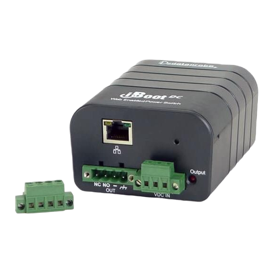
Congratulations on purchasing the best
network controlled power switch available.
The iBoot-DC provides you the ability to
reboot crashed devices with the click of a
mouse.
Be sure to read up on all the
features of the iBoot-DC Including:
Web Based setup and control
iBoot Cloud Service: Control all your
iBoots from one web portal.
AutoPing: Automatic monitoring and action
for failed equipment.
Event Scheduling for real-time power
control.
Telnet setup and control
Management Utility: Easy Setup,
Firmware upgrades and Reset to Factory
Default.
Easy Software Integration: Protocols to
build your own custom applications.
Local Link Multicast Name Resolution:
Use to access on supporting networks.
Reboot Only Mode: Prevents accidental
switching off to ensure continuous operation.
1.
2.
3.
4.
5.
6.
7.
iboot-dc_v181024e
1. Table of Contents
1
8.
2
9.
3
6
8
11
18
Web Enabled
Power Switch
October 2018
21
25
25
26
27
28
Advertisement
Table of Contents

Related Manuals for Dataprobe iBoot-DC


Summary of Contents for Dataprobe iBoot-DC
-
Page 1: Table Of Contents
Power Switch October 2018 Congratulations on purchasing the best network controlled power switch available. The iBoot-DC provides you the ability to reboot crashed devices with the click of a mouse. Be sure to read up on all the features of the iBoot-DC Including: ... -
Page 2: General Description
2. General Description The iBoot-DC is a network attached, IP addressed, web controlled AC power switch. Anyone with a web browser can access iBoot-DC to perform power On, Off or Power Cycle (Reboot or Power Burst). iBoot-DC uses two levels of password for security. -
Page 3: Hardware Installation
3. Hardware Installation 3.1. Ethernet Connections iBoot-DC supports 10/100 Ethernet using the cable supplied, or other suitable unshielded twisted pair (Cat 5) cabling. Activity (green) and 100Mb (amber) LEDs on the network connector indicate when the network connection is properly established and when the connection is 100 Mbit/s. - Page 4 3.3. Connecting Negative Voltages iBoot-DC will accept a negative (relative to ground) power source i.e. -48VDC. Insure the power leads are connected so that "+" terminal voltage is positive RELATIVE to the "-" terminal voltage. Do Not connect Chassis Ground when using –VDC Power.
- Page 5 Step 2 3. The unit is 3. Ready for ready for wall DIN rail mounting. mounting. 4. Use M3 or #4 screws (not included) for attachment to suitable surface iboot-dc_v181024e iBoot-DC Page 5...
-
Page 6: Initial Configuration
Enter New IP Address for iBoot Note: The IP address can only be set within the first two minutes of powering up the iBoot-DC or pressing the reset button (see Section 11). The Setup Utility will only work with iBoots on the same physical subnet as the PC. - Page 7 5. Click OK when done. Once the IP Address is set, other all other operational features of the iBoot-DC can be set up. Click on Discover again to refresh the display, highlight the desired iBoot-DC and click on Manage | Launch Browser.
-
Page 8: Web Browser Operation
Open your browser and enter the IP address of iBoot-DC into the address bar. If you have changed the IP address by any of the methods described or used DHCP, enter that address, otherwise, use the default IP address 192.168.1.254... - Page 9 Trigger counter is provided. If the iBoot-DC is connected to a time server (see Section 6.3), The Home page will also show the five most recent history events, including the Outlet, Action, User and Time/Date of each event. The iBoot-DC holds the last 32 events in memory.
- Page 10 5.4. URL Control iBoot-DC can be controlled directly by sending a completely formed URL through a browser window or HTTP command. The URL syntax for control is: http://<address>?s=<status>&t=<time>&u=<user>&p=<password> Where: <address> = the IP Address of the device, or DNS name that resolves to the IP Address, Including any HTTP Port if not standard 80 <status>...
-
Page 11: Web Setup
(See section 6.9) Initial State: The outlet can be set to the state it will assume when the iBoot-DC is powered up or reset The choices are: On, Off and Last, meaning the state it was in when the power was removed or reset commenced. - Page 12 Telnet Port: This setting is used to allow access to the iBoot-DC via telnet by ports other than standard 23. DxP Port: This setting is used to allow access to the iBoot-DC via Dataprobe Exchange Protocol (DxP) via ports other than standard 9100.
- Page 13 (like turning on an indicator or siren). You set one or two IP addresses to be periodically pinged. When iBoot-DC no longer detects a response from these addresses, programmed power control function is actuated.
- Page 14 With AutoPing operational, the main iBoot-DC page will display the current status of this feature. The status will be OK to indicate that iBoot-DC is receiving responses to the ping, or that the fail counter has not yet been exceeded.
- Page 15 Clear: Delete the scheduled event. Click Save to save the current settings. Click Reset to delete any unwanted changes. 6.8. Password Settings The iBoot-DC supports three modes of user and password operation. Login Required: This mode supports both User and Admin users.
- Page 16 Command Line Interface (CLI) control will not process “set outlet off” If cloud control is enabled, the Off command will not be processed. Disabled When the feature is disabled, all the modes that can turn the power off will be available and functioning. iboot-dc_v181024e iBoot-DC Page 16...
- Page 17 (DNS) packet format that allows hosts to perform name resolution on the same local link. On most networks you will be able to access the iBoot-DC by its device name when on the local network. By default the name is iBoot-DC-xxxx where the xxxx is the last 4 segments of the MAC address for your iBoot-DC.
-
Page 18: Iboot Cloud Service
Insure Proper iBoot-DC Firmware iBoot Cloud Service requires version iBoot-DC Firmware version 1.21.99 or greater. Check the bottom of any web page of the iBoot for the firmware version. If needed, download and install the proper iBoot Firmware from http://dataprobe.com/support-iboot-dc/... - Page 19 Locations: Group all iBoots by location. Click on any location to display or hide all the iBoots at that location. Account: Display and edit account information and obtain account access history. Help: Links to the iBoot Cloud Forum and Dataprobe support pages. iboot-dc_v181024e iBoot-DC Page 19...
- Page 20 Device Name that is displayed on the iBoot web page. To add locations, click on the Locations button on the menu bar, and then click Add Location. Name the location and click the Add Location button. iboot-dc_v181024e iBoot-DC Page 20...
-
Page 21: Command Line Interface
8. Command Line Interface The iBoot-DC Command Line Interface (CLI) provides a text based method for communicating with the iBoot. The syntax of the CLI uses a basic Set (change a variable) and Get (retrieve a variable). The CLI is accessed either through the Telnet protocol, which requires a Telnet client program. - Page 22 This command sets the ip address setting mode. Static mode DHCP locks the address as set, dhcp mode allows DHCP server to assign address. This command is used to set the iBoot-DC’s ip address. set ipaddress <dotted 192.168.1.254 decimal> This command is used to set the iBoot-DC’s subnet mask.
- Page 23 Sets single AutoPing or two AutoPing relationship And or Or. Single and | or> set autoping action <none | on- This command is used to set the action that the iBoot-DC will None latch | on-follow | off-latch | off- perform when the autoping triggers.
- Page 24 Reboot Required> This is the prompt that will be displayed whenever there have been changes made that require a reboot. This prompt will remain the active prompt until the iBoot-DC has been rebooted. iboot-dc_v181024e iBoot-DC Page 24...
-
Page 25: Dxp Protocol
1) Insure that the Upgrade Enable checkbox is checked in the Network Setup web page of the iBoot-DC 2) Run the Device Management Utility, available at the link above. If the iBoot-DC you would like to upgrade is not visible in the list box, either Select Device | Discover from the menu to locate iBoot-DC units on the local network, or Select Device | Add from the menu to add the IP address of the iBoot-DC. -
Page 26: Troubleshooting
Troubleshooting The iBoot-DC has a recessed pushbutton switch in the event the unit is not performing as expected. Use the pushbutton as follows: Action Result Momentary Soft Reset. Will not change outlet status. 10 Seconds push Reset to Factory Defaults. Hold the button in until the Outlet LED is blinking, then release. -
Page 27: Specifications
IP Addressed, DHCP assigned or Static Internal HTTP Web Server Forms Processing Browser required Telnet Server User Settings Record your Setup here for reference Location: HTTP Port: MAC Address: Auto-Ping Address: IP Address: Auto-Ping Port: Subnet Mask: Heartbeat Port: Gateway: iboot-dc_v181024e iBoot-DC Page 27... -
Page 28: Technical Support And Warranty
90 days, whichever is greater. If Purchased from Dataprobe Inc.; Service under this Warranty is obtained by shipping the product (with all charges prepaid) to the address below. Seller will pay return shipping charges within the United States. Call Dataprobe Technical Service to receive a Return Materials Authorization (RMA) Number prior to sending any equipment back for repair.
Need help?
Do you have a question about the iBoot-DC and is the answer not in the manual?
Questions and answers