Advertisement
Quick Links
What's Included
•
iBoot-G2S Unit
•
Power Input Cable for North America
•
Power Outlet Cable for North America
•
Network Cable
•
USB Cable
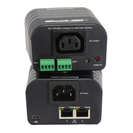
Connections
1. Connect Network.
network using the cable supplied, or other suitable unshielded twisted pair (Cat 5)
cabling. Optionally, connect the other to a networked device. When power is
connected to the iBoot-G2S, the green LEDs on the network connectors indicates
when the network connection is properly established.
2.
Connect Powered Device.
to the IEC receptacle marked A/C Outlet. An IEC-320 to North American (NEMA 5-
15) power cord is included for connecting the iBoot outlet to the device to be
controlled. If the device has a power switch, turn it on, to allow iBoot-G2+ to control
the power.
Make sure that the combined load of all controlled devices
does not exceed 12 Amps for 105-125VAC or 10 Amps for 210-
240VAC.
3. Connect Power Mains
labeled AC Input, and the other end to your AC source.
different terminating plug is required, be sure it is properly rated and meets all the
required local electrical standards.
Web Browser Access
Factory Default IP Address: DHCP Set or 192.168.1.254
Factory Default Security Credentials:
Role
Username
Administrator
admin
Discover and/or Set the IP Address
If you network supports DHCP, the IP address of the iBoot will be
automatically assigned. Find the IP Address of the iBoot using either from the
DHCP Router/Server or use the Dataprobe Device Management Utility (DMU),
available at dataprobe.com/support-iboot-g2s.
DMU.
Point your browser to the IP Address of the iBoot, then enter the Administrator
Username and Password to access the complete setup features. Once the
user is validated, the Control and Status is displayed.
To control the power, select the Main Outlet checkbox, and then click on the
appropriate power button. During power cycling, the Power Status bar will
indicate the temporary status, with a blue background. Once the cycle is
complete, the status bar will revert to its original condition.
iBoot-G2S Quick Start
iBoot-G2S supports dual 10/100 Connect one to the
Connect the device to be powered ON and OFF
Connect the supplied power cord to the connector
Password
admin
See Page 2 for more in the
© 2018 Dataprobe Inc.
Quick Start Guide
Available Online at
dataprobe.com/support-iboot-g2s
•
Complete Product Manual
•
Device Management Utility
•
Latest iBoot-G2S Firmware
•
Software Developer Tools
If a power cord with a
Fig.1 Connect Network
Fig. 2 Connect Device
Fig. 3 Connect Power
Fig. 4 Status and Control Page
V180802N
Advertisement

Related Manuals for Dataprobe iBoot-G2S


Summary of Contents for Dataprobe iBoot-G2S
-
Page 1: Quick Start Guide
(Cat 5) cabling. Optionally, connect the other to a networked device. When power is connected to the iBoot-G2S, the green LEDs on the network connectors indicates when the network connection is properly established. -
Page 2: Changing The Ip Address
Fig. 5 Device Management Utility work with iBoots on the same physical subnets as the PC Complete instructions for the DMU are provided with the download, and in the full iBoot-G2S Manual. 2. Web Page Setup From the home page, click on Setup, then Network. -
Page 3: Mounting Options
Mounting Options iBoot-G2S is suitable for desktop or shelf mounting. A mounting kit for wall and DIN rail mounting is available. Order part: 1920034 iBoot-MK Mounting Kit for iBoot-G2 Series 1920034 Mounting Kit iBoot G2 Series Installing the Wall Mounting Kit...
Need help?
Do you have a question about the iBoot-G2S and is the answer not in the manual?
Questions and answers