Table of Contents
Advertisement
Quick Links
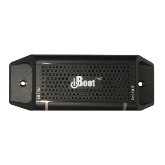
Congratulations on purchasing the best network controlled power switch available. The iBoot-PoE-P
provides you the ability to reboot crashed devices automatically or with the click of a mouse. Be sure to
read up on all the features of the iBoot-PoE-P Including:
PoE Extender 100m
PoE Passive 9 - 72 VDC up to 90 Watts
Web Based setup and control
Automatic Reboot using AutoPing and Traffic Monitor.
Event Scheduling for real-time power control.
Telnet setup and control
Management Utility: Easy Setup, Firmware upgrades and Reset to Factory Default
iBoot Cloud Service: Control all your iBoots from one web portal.
1.
2.
3.
4.
5.
6.
7.
Table of Contents
2
8.
5
9.
7
10
13
18
PoE Passive
Extender with Reboot
April 2019
20
22
28
28
29
30
31
Advertisement
Table of Contents

Related Manuals for Dataprobe iBoot PoE-P


Summary of Contents for Dataprobe iBoot PoE-P
-
Page 1: Table Of Contents
PoE Passive Extender with Reboot April 2019 Congratulations on purchasing the best network controlled power switch available. The iBoot-PoE-P provides you the ability to reboot crashed devices automatically or with the click of a mouse. Be sure to read up on all the features of the iBoot-PoE-P Including: ... -
Page 2: General Description
Service. A simple Web browser interface makes it easy to control power from anywhere in the world with a click of a mouse. iBoot-PoE-P also supports Telnet for text commands, as well as Dataprobe’s Exchange Protocol (DxP) for interfacing to a variety of Dataprobe products and custom software development. - Page 3 1.2. Automatic Reboot iBoot-PoE-P provides two ways to monitor your application and provide automatic reboot when configurable conditions are met AutoPing The AutoPing feature allows iBoot-PoE-P to automatically detect failed equipment and perform a timed reboot or other power control function. You set one or two IP addresses to be periodically pinged. When iBoot-PoE-P no longer detects a response from these addresses, the programmed power control function is actuated.
- Page 4 Dataprobe Exchange Protocol (DxP) This protocol allows Dataprobe products to communicate across networks, and allows developers to design custom applications to integrate iBoot-PoE-P into unique applications. For more information about DxP, contact Dataprobe Support team (support@dataprobe.com). iboot-poe-p_v190422w...
-
Page 5: Hardware Installation
2. Hardware Installation 2.1. Auto Configuration Sequence In most cases, the iBoot-PoE-P can completely configure itself on initial installation to identify all network elements and automatic reboot of failed devices. For the best results follow this sequence when installing the iBoot-PoE-P for the first time. 1. - Page 6 2.3. Power Connection Model iBoot-PoE-P Power is supplied by the Power Source Equipment (PSE) on the NET IN connector. No external Power Supply is necessary. Voltage Range: 9 – 72 VDC The iBoot-PoE-P supports 802.3af Mode A, Mode B and 4PPoE wiring specifications. 4PPoE Mode B Mode A...
-
Page 7: Initial Configuration
IP Address and be ready to use. You can discover the IP Address through your Server/Router, or use Dataprobe’s Device Management Utility (DMU). If your network does not use DHCP, the iBoot-PoE-P will default to IP Address 192.168.1.254 3.2. - Page 8 Factory Defaults. This must be done within the first two minutes of powering up the iBoot or pressing the reset button. Get all the details on the DMU at http://dataprobe.com/support-dmu/ 3.3. Other ways to set the IP Address 1. Web Browser via the Set-up Page – See Section 5 2.
- Page 9 The following are the standard settings that will be used for self-configuring AutoPing and Traffic Monitor. All these settings can be changed with either the web setup or Command Line Interface. See Section 5.5 for an explanation of these settings. AutoPing Setting Address: IP Address of Powered Device...
-
Page 10: Web Browser Operation
4. Web Browser Operation 4.1. Password Protection iBoot-PoE-P uses two username/password credential sets, one for power control only (User) and one that also provides access to the setup functions (Admin). This configuration can be changed to require Administrator credentials at all times or allow unsecured User level control. - Page 11 4.3. Control and Status Page Once the user is validated, the Control and Status page is displayed. (Only one person can be connected to the iBoot-PoE-P at a time.). This page provides automatic updates every 5 seconds. To control the power, click on the appropriate button. During power cycling, the Power Status bar will indicate the temporary status, with a blue background.
- Page 12 4.4. URL Control iBoot-PoE-P supports a RESTful API and can be controlled directly by sending a completely formed URL through a browser window or HTTP command. The URL syntax for control is: http://<address>?s=<status>&t=<time>&u=<user>&p=<password> Where: <address> = the IP Address of the device, or DNS name that resolves to the IP Address, plus any HTTP Port if not standard 80 <status>...
-
Page 13: Web Setup
5. Web Setup iBoot-PoE-P setup section consists of several pages. Access any page via the buttons on the left of the page. Each time a setting is changed click on the Save button for that page to save the changes before moving to the next page. - Page 14 Telnet Port: This setting is used to allow access to the iBoot-PoE-P via telnet by ports other than the standard for telnet 23. DxP Port: This setting is used to allow access to the iBoot-PoE-P via Dataprobe Exchange Protocol (DxP) via ports other than standard 9100.
- Page 15 5.5. Automation Automation settings page shows the current status of the AutoPing and Traffic Monitors that are set. It also allows Automatic Configuration of these settings. The Traffic Monitor shows the current throughput. This will update each time the Refresh button is pressed.
- Page 16 With AutoPing operational, the main iBoot-PoE-P page will display the current status of this feature. The status will be OK to indicate that iBoot-PoE-P is receiving responses to the ping, or that the fail counter has not yet been exceeded. If the fail count has been exceeded, the status will change to FAIL.
- Page 17 Time: Set the initial time for the event. The format for the time is hh:mm with hours in 24 hour format. Repeat: Set the repeat multiplier, if desired. Set the number from 0 to 999 and either Days, Hours, or Minutes. To have the schedule repeat every two days, set this number to 2.
-
Page 18: Disable Off
6. Disable Off This new feature in version 1.2.30 and above ensures that the power to the controlled device will always be on whenever possible. No accidental turning or leaving the power off is possible. To use the “Disable Off” feature WEB –... -
Page 19: Local Link Multicast Name Resolution
7. Local Link Multicast Name Resolution The Link-Local Multicast Name Resolution ( LLMNR ) is a protocol based on the Domain Name System (DNS) packet format that allows hosts to perform name resolution on the same local link. On most networks you will be able to access the iBoot-PoE-P by its device name when on the local network. By default the name is iBoot-PoE-P-xxxx where the xxxx is the last 4 segments of the MAC address for your iBoot- PoE-P. -
Page 20: Iboot Cloud Service
While the Cloud Service is in Beta stage, the firmware in the iBoot is fully tested and released by Dataprobe. If you do not enable the cloud capabilities of the iBoot, you can expect continuous and dependable operation. 8.1. - Page 21 Cycle Off Select the outlet you want to control, then Click On, Off or Cycle from top bar. Full cloud operation and feature descriptions are available online here: http://Dataprobe.com/iboot-cloud-service iboot-poe-p_v190422w iBoot-PoE-P Page 21...
-
Page 22: Command Line Interface
The iBoot-PoE-P Command Line Interface (CLI) provides a text based method for communicating with the iBoot -PoE-P. The syntax of the CLI uses a basic Set (change a variable) and Get (retrieve a variable). The CLI is accessed either through the Telnet protocol, which requires a Telnet client program. Dataprobe provides a simple Telnet Client program (EZ Term) at http://dataprobe.com/support-iboot-poe/. 9.1. CLI Access Open the Telnet client and connect to the IP address set for the iBoot-PoE-P . - Page 23 set cycle <1-999> This command is used to set the cycle time, in seconds get cycle This command returns the current cycle time set upgrade enable <yes | no> Enables or disables the ability to upload new firmware to the iBoot-PoE-P. get upgrade enable This command displays the upload enable status.
- Page 24 set dxp port <0-65535> This command sets the port that the iBoot-PoE-P’s DxP protocol service listens for 9100 incoming connections on. When set to 0 the Protocol service is disabled. Note: At least one of the above MUST NOT be 0. The CLI will protect against all 3 from being set to 0.
- Page 25 set traffic monitor <enable | disable> Enable or disable the traffic monitor Enabled set traffic monitor failtime <1-999> Fail time set traffic monitor restarttime <0-999> Restart time set traffic monitor cycles <0-99> Number of cycles set traffic monitor min Min band width <0-125000000>...
- Page 26 Event Commands These commands are only available to the administrator. get events This command displays all scheduled events as shown below. Example: Date Time Repeats Action 1. 01/13/2013 16:00 every 1 Day(s) 2. 01/13/2013 16:15 every 0 Day(s) 3. 01/15/2013 17:00 every 1 Hour(s) Cycle 4.
- Page 27 Prompts The CLI will use the following prompts: User> This prompts the user to enter his user name (user or admin). This is the first prompt that the user is presented with. Password> This prompts the user to enter his password. iBoot >...
-
Page 28: Dxp Protocol
DxP Protocol iBoot-PoE-P supports the Dataprobe Exchange Protocol (DxP) for inter device communications and to allow software developers to integrate Dataprobe product into custom applications. Through the DxP protocol, the developer can: Turn on and off power to the Outlet ... -
Page 29: Troubleshooting
Troubleshooting The iBoot-PoE-P has a recessed pushbutton switch in the event the unit is not performing as expected. Use the pushbutton as follows: Action Result Momentary Soft Reset. Will not change output status. 5 Seconds push Reset to Factory Defaults. Hold the button in until the Outlet LED is blinking, then release. -
Page 30: Specifications
Specifications 13.1. Physical 1.85” 47.0 mm Height 4.9” 24.5 mm Width 1.35” 34.3 mm Depth Weight 3.9 oz 110g MTBF Temperature Maximum Operating Temperature dependent on current draw: 0-30 watts 70 degrees C 31-40 watts 60 degrees C 41-60 watts 50 degrees C 61-90 watts 40 degrees C 0 degrees C. -
Page 31: Technical Support And Warranty
90 days, whichever is greater. If Purchased from Dataprobe Inc.; Service under this Warranty is obtained by shipping the product (with all charges prepaid) to the address below. Seller will pay return shipping charges within the United States. Call Dataprobe Technical Service to receive a Return Materials Authorization (RMA) Number prior to sending any equipment back for repair.
Need help?
Do you have a question about the iBoot PoE-P and is the answer not in the manual?
Questions and answers