Table of Contents

Subscribe to Our Youtube Channel
Related Manuals for Dataprobe iBoot


Summary of Contents for Dataprobe iBoot
-
Page 1: Table Of Contents
Control & Status Page Auto-Ping Setup Page Hardware Installation Passwords Page Ethernet Connections Forgotten Password A/C Power Connections Program Control iBoot Configuration Direct TCP Control Setting IP Address User Settings Using DHCP Using Web Browser Access Specifications Using ibootrst.exe Tech Support & Warranty... -
Page 2: Important Safety Information
Ver 1.5 Page 2 IMPORTANT SAFETY INSTRUCTIONS When using this product, basic safety precautions should always be followed to reduce the risk of fire, electric shock, and injury to persons, including the following: Read and understand all instructions. Follow all warnings and marked on the product. -
Page 3: General Description
Page 3 General Description The iBoot is a network attached, IP addressed, Web Controlled AC power switch. Anyone with a web browser can access iBoot to perform power On, Off or Reboot (timed power shutdown). iBoot is password protected for security. -
Page 4: Auto-Ping
Ping'ed. When iBoot no longer detects a response from the address, the programmed power control function is actuated. ♦ Use Auto-Ping Locally: Put iBoot next to the device to be monitored and reboot it automatically when it no longer responds. ♦... -
Page 5: Hardware Installation
CAUTION Be sure to check that the unit is set to the correct operating voltage before plugging in the unit or applying AC power. Make certain to disconnect the iBoot from the AC power source before making any control connections. -
Page 6: Ethernet Connections
Ver 1.5 Page 6 Ethernet Connections iBoot supports 10/100 Ethernet using unshielded twisted pair (Cat 5) cabling. Uplink and Downlink connections are provided. Use the Uplink jack to connect to an Ethernet hub and the Downlink jack to connect to an additional piece of networking equipment. -
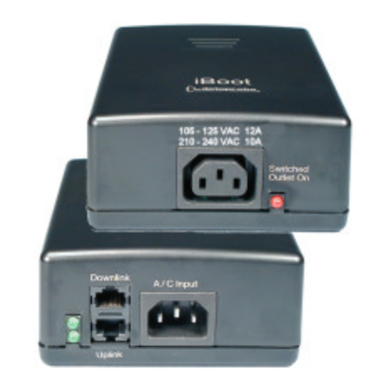
Page 7: Ac Power Connections
Ver 1.5 Page 7 AC Power Connections Select Input Voltage Before Making Any Connections 115V for 105 to 125VAC 230V for 210 to 240VAC Connect to Power Source Use Included Cord for North America. For other A/C Input Downlink locations, use locally approved power cord. - Page 8 Ver 1.5 Page 8 iBoot can be set for operating voltages of 105-125 VAC or 210- 240 VAC by setting the voltage selector switch located on the side of the unit to the appropriate position 115 or 230. Make sure the switch is set to the correct position before applying power.
-
Page 9: Iboot Configuration
IP address from a DHCP Server. If you network has a DHCP server, it will automatically assign an IP address to iBoot the first time it is connected and powered up. 1. Setting the IP address from a DHCP Server A DHCP server will automatically assign an IP address (dynamic address) as well as Subnet Mask and Gateway to the iBoot. - Page 10 To use ibootrst.exe, the computer running the program must be on the same subnet and network segment as the iBoot is to be programmed to. Same subnet can be directly connected or connected through Ethernet hubs. (NOT routers or switches) To use ibootrst.exe...
- Page 11 Using ARP you use a computer to set the IP address. The IP address assigned to iBoot must be use the same network segment as the computer assigning the address. ARP does not work across routed or switched networks.
-
Page 12: Web Browser Operation
Page 12 Web Browser Operation Password Protection iBoot uses two passwords, one for normal use and one that also provides access to the setup functions. From the factory, both passwords are the same. (PASS) Open your browser and enter the IP address of iBoot into the address bar. - Page 13 Ver 1.5 Page 13 cycle, click on either Power On or Power Off buttons. iBoot will assume the status selected. Use the Refresh link to obtain the latest status of iBoot. Using your browser's refresh button can lead to inadvertent power switching.
-
Page 14: Setup Page
This will be automatically set if using DHCP HTTP Port: This setting is used to allow access to iBoot on a port other than the Web standard Port 80. If the port is changed, you will need to identify the port number when you enter iBoot's IP address into your browser: if the new port is 9100 then use http://192.168.1.254:9100 to access iBoot. - Page 15 ♦ Power Cycle Once Power On – Latch: Upon loss of ping response, iBoot will power on and remain so until changed via the web, ibootctl.exe or direct messaging. Power On – Follow: Upon loss of ping response, iBoot will power on. When the ping response returns, iBoot will power off.
-
Page 16: Passwords Page
Two passwords are provided. The first password allows access to the control of iBoot, but not to the Setup functions. When this password is used, the main screen will not have a link to Setup. The Setup Password allows access to both the Main Screen and the Setup Screen. -
Page 17: Program Control
Ver 1.5 Page 17 Program Control ibootctl.exe Dataprobe provides a remote control program to control iBoot directly. This program is useful for creating simple desktop icons for specific power functions for one or more iBoots. It can also be run from a command line and can be called by other programs. -
Page 18: Specifications
Ver 1.5 Page 18 Specifications Model iBoot A/C Power Control Module Ver 1.5 SKU: 1410010 Physical Height 2.25 in. Width 4.50 in. Depth 6.00 in. Weight 1.25 lb. Input: 3 Prong, Male, IEC 320 input connector. Input Cord Spec...16AWGX3C 10A 250 UL/CSA/VDE Rated (1.25mm... -
Page 19: Tech Support & Warranty
Page 19 TECHNICAL SUPPORT, RETURNS and WARRANTY Dataprobe Technical Support is available 8:30AM to 5:30PM ET to assist you in the installation and operation of this product. To obtain Technical Support call our Tech Support Hotline at 201- 967-8788, or Email us at tech@dataprobe.com. -
Page 20: More Power Control Solutions
More Power Control Solutions 8 Outlet Remote Control Power Strips Rack Mounted 8 outlet power strips can be controlled by Web / Telnet / Modem / Serial or DTMF dialing tones. Visit www.dataprobe.com/power/8outlets.html Phone Controlled Power Switch PowerPAL offers remote control of a single A/C outlet using any tone dial telephone.
Need help?
Do you have a question about the iBoot and is the answer not in the manual?
Questions and answers