Table of Contents
Advertisement
Quick Links
User MANUAL
OAKWORKS
Spine Positioning System II
CresCent
FaCe Pad
radioluCent
Frame With
adjustable
FaCe rest
8" x 22" x 2"
7" x 12" x 1½"
(20 x 56 x 5 cm)
(18 x 30 x 4 cm)
large
small
reCtangular
reCtangular
adjuster Pad
adjuster Pad
www.oakworksmed.com · 717.235.6807
®
Contoured torso
suPPort Pad
Contoured
torso Wedge
Carry Case
made in the USA
with US & imported parts
8" (20cm)
semi-
round
bolster
Advertisement
Table of Contents

Subscribe to Our Youtube Channel
Related Manuals for OAKWORKS Spine Positioning System II


Summary of Contents for OAKWORKS Spine Positioning System II
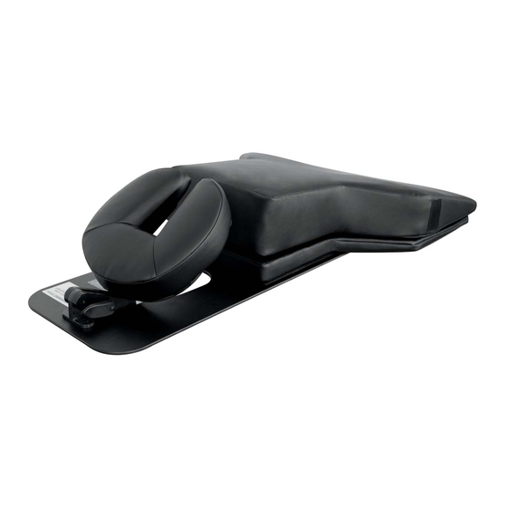
- Page 1 User MANUAL OAKWORKS ® Spine Positioning System II Contoured torso CresCent suPPort Pad FaCe Pad radioluCent Frame With adjustable FaCe rest Contoured torso Wedge 8” x 22” x 2” 7” x 12” x 1½” (20 x 56 x 5 cm)
- Page 2 Oakworks® Medical Equipment, a Oakworks®, Inc. shall not be liable for division of Oakworks®, Inc. incidental or consequential damages in connection with or arising out of the furnishing, performance, or use of this Oakworks®...
-
Page 3: Table Of Contents
Directions for Use Preparation for Use ...................... 6 Face Rest Platform Adjustment ................... 6 Torso Support Strap ..................... 7 Transporting the Spine Positioning System II ............7 Imaging Scenarios ......................8-14 Cleaning & Disinfection ....................15 Inspections & Maintenance ..................15-16 Warranty Information ...................... -
Page 4: Introduction
InTRODUCTIOn / PRODUCT USe DeSCRIPTIOn / SyMbOl IDenTIfICATIOn InTRODUCTIOn The Spine Positioning System II is an integral component of the pain management fluoroscopy suite. With this system procedural set up time is reduced, patient comfort is enhanced and unwanted movement is minimized. Most impor- tantly, the target anatomy is more readily visualized which allows the physician to perform spine procedures in a more efficient and secure manner. -
Page 5: Safety Instructions
Do not overhang the radiolucent frame beyond the warning line on the frame. Operate the C-arm of the fluoroscopy system with the Spine Positioning System II in place before using the device with a patient for the first time. Make sure there is adequate clearance to permit free C-arm rotation for both the patient and the positioning device. -
Page 6: Product Description & Photos
PRODUCT DeSCRIPTIOn Spine Positioning System II Contoured torso suPPort Pad CresCent FaCe Pad radioluCent Frame With adjustable FaCe rest Contoured torso Wedge 8” x 22” x 2” 7” x 12” x 1½” (20 x 56 x 5 cm) (18 x 30 x 4 cm) -
Page 7: Radiolucent Frame
PRODUCT DeSCRIPTIOn RADIOlUCenT fRAMe Used to support the Torso Support and Crescent Face Pad. One cam lock facilitates cervical flexion and extension. Cervical Support Adequate free space System under see through face section for aeration, supple- Cam lock mental oxygen, jaw/face contact as necessary;... -
Page 8: Contoured Torso Wedge
PRODUCT DeSCRIPTIOn COnTOUReD TORSO WeDge The Contoured Torso Wedge is constructed of dense foam This provides enhanced patient stability and conveniently reduces shoulder interference during cervical procedures. SMAll ReCTAngUlAR ADjUSTeR PAD The 7” x 12” (18 x 30 cm.) Small Rectangular Adjuster pad is used to reduce lumbar lordosis and/or increase chest height to allow for shoulders to naturally descend out of the plane of the cervical and thoracic spine. -
Page 9: Directions For Use
DIReCTIOnS fOR USe PRePARATIOn fOR USe CAUTIOn Do not overhang the platform frame beyond the Warning line on the frame. Unpack and inspect all components. Identify the components and their use with the pictures located in the Product Description Section of this manual. All components are shipped in a clean but not sterile condition. -
Page 10: Torso Support Strap
Radiolucent Frame Spine Positioning System Pads Open the cam lock on the adjustable face rest When placing the Spine Positioning System II and rotate the face rest flat against the base in the Carry Case, put some pads, wedges or frame. -
Page 11: Imaging Scenarios
A patient safety strap must be used during all procedures. The following imaging scenarios of patients will demonstrate: 1. Various body types using the Spine Positioning System II (SPS II) 2. Their positioning and specific configurations of the SPS II used in particular clinical situations 3. - Page 12 IMAgIng SCenARIOS WARnIng A patient safety strap must be used during all procedures. Patient - don Components used: Radiolucent Frame, Crescent Face Pad, Contoured Torso Support Pad, Large Adjuster Pad, 8” Semi-Round Bolster (not pictured) SPS II set up for Don shown here Don in the SPS II while obtaining an Lateral image of the lumbar spine oblique image of the lumbar spine...
- Page 13 IMAgIng SCenARIOS WARnIng A patient safety strap must be used during all procedures. Patient - liz Components used: Radiolucent Frame, Crescent Face Pad, Contoured Torso Support Pad, Contoured Torso Wedge, 8” Semi-Round Bolster (not pictured) SPS II set up for liz shown here Liz in the SPS II while obtaining an Liz in the SPS II while obtaining a lateral AP image of the upper thoracic spine.
- Page 14 IMAgIng SCenARIOS WARnIng A patient safety strap must be used during all procedures. Patient - mary Components used: Radiolucent Frame, Crescent Face Pad, Contoured Torso Support Pad, Contoured Torso Wedge, 7” x 12” Rectangular Adjuster Pad, 8” Semi-Round Bolster (not pictured) SPS II set up for Mary shown here Mary in the SPS II while obtaining an AP image through the C1-2 segment...
- Page 15 IMAgIng SCenARIOS WARnIng A patient safety strap must be used during all procedures. Patient - Carl Components used: Radiolucent Frame, Crescent Face Pad, Contoured Torso Support Pad, Contoured Torso Wedge, 8” Semi-Round Bolster (not pictured) SPS II set up for Carl shown here Carl in the SPS II while obtaining an Right thoracic oblique image to visual- AP image of the mid-thoracic spine...
- Page 16 IMAgIng SCenARIOS WARnIng A patient safety strap must be used during all procedures. Patient - debbie Components used: Radiolucent Frame, Crescent Face Pad, Contoured Torso Support Pad, Contoured Torso Wedge, Small Adjuster Pad, 8” Semi-Round Bolster (not pictured) SPS II set up for Debbie shown here Debbie in the SPS II while obtaining a AP image of the cervical spine while lateral cervical image.
-
Page 17: Imaging Scenarios
IMAgIng SCenARIOS WARnIng A patient safety strap must be used during all procedures. Patient - jane Components used: Radiolucent Frame, Crescent Face Pad, Contoured Torso Support Pad, Contoured Torso Wedge, 8” Semi-Round Bolster (not pictured) SPS II set up for jane shown here Jane in the SPS II while obtaining a The lower cervical interlaminar lateral image of the cervical spine. -
Page 18: Cleaning & Disinfection
CleAnIng & DISInfeCTIOn / InSPeCTIOnS & MAInTenAnCe CleAnIng & DISInfeCTIOn WARnIng Before cleaning with any liquid cleaner be sure to unplug the power cord from the outlet. Use a 10% sodium hypochlorite (bleach) solution or Recommended Disinfectants on all surfaces. Clean all sides of each upholstered section. -
Page 19: Warranty Information
2. Hold the cam with other hand. Good (no gap) 3. Tighten the cam until there is no gap between the 2 metal parts. WARRAnTy View complete warranty details at www.oakworks.com PRODUCT SPeCIfICATIOnS Component Aluminum equivalence Dimensions radiolucent Frame 1.20 mm @ 100 kVp, HVL of 3.6 mm... -
Page 20: Contact Information
User MANUAL OAKWORKS ® Spine Positioning System II COnTACT InfORMATIOn: Inc. ® akworks 923 East Wellspring Road New Freedom, PA 17349 Phone: 717-235-6807 FAX: 717-235-6798 www.oakworksmed.com FDA Listed Manual Part Number: MMMNUP0003-EN Revision: B Revision date: 04/24/2015 made in the USA with US &...
Need help?
Do you have a question about the Spine Positioning System II and is the answer not in the manual?
Questions and answers