Burkert AirLINE 8652 Quick Start Manual
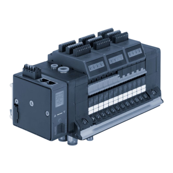
Modular valve terminal for pneumatics
Hide thumbs
Also See for AirLINE 8652:
- Operating instructions manual (96 pages) ,
- Quick start manual (39 pages) ,
- Operating instructions manual (122 pages)

Related Manuals for Burkert AirLINE 8652


Summary of Contents for Burkert AirLINE 8652
- Page 1 Type 8652 AirLINE Modular valve terminal for pneumatics Modulare Ventilinsel für Pneumatik Îlot de vannes modulaire pour système pneumatique Quickstart English Deutsch Français...
- Page 2 We reserve the right to make technical changes without notice. Technische Änderungen vorbehalten. Sous réserve de modifications techniques. © Bürkert Werke GmbH & Co. KG, 2017-2019 Operating Instructions 1902/07_EU-ML_00810542 / Original DE...
-
Page 3: Table Of Contents
Type 8652 Type 8652 Contents 7.2 Electrical connection electronics module with The QuicksTarT ..............4 digital inputs .............. 19 1.1 Definitions of terms ............. 4 7.3 Electrical connection Type 6534 valves for Symbols ............... 4 safety-related shut-off (SIA variant) ......19 inTended use ..............5 Pneumatic connection ..........22 Basic safeTy insTrucTions .......... 6 sTarT-up ................ -
Page 4: The Quickstart
▶ Persons, who work on the device, must read and understand these instructions. CauTIon The operating instructions and data sheets for Bürkert Warns of a possible danger. devices can be found on the Internet at: ▶ Failure to observe the warning may result in moderate or www.burkert.com minor injuries. Definitions of terms noTe Term Is used in these instructions Warns of damage to property. -
Page 5: Intended Use
Type 8652 Intended use inTended use The valve terminal airline Type 8652 is designed for con- The valve terminal is only intended for use in industrial trolling and recording the switching statuses of pneumati- environments. cally operated process valves. The valve terminal is not suitable for use in applications that ▶... -
Page 6: Basic Safety Instructions
Type 8652 Basic safety instructions Basic safeTy insTrucTions risk of injury due to unintentional activation and uncontrolled start-up of the device and system. These safety instructions do not consider any contingencies or incidents which occur during assembly, operation and maintenance. ▶... -
Page 7: General Information
Email: info@burkert.com supply voltage is switched on! International Contact addresses can be found on the final pages of the printed Quickstart. And also on the Internet at: www.burkert.com Warranty The warranty is only valid if the device is used as intended in accor- dance with the specified application conditions. Information on the Internet The operating instructions and data sheets for Bürkert products can be found on the Internet at: www.burkert.com... -
Page 8: Technical Data
Type 8652 Technical data Technical daTa Operating conditions Conformity noTe The device conforms to the EU directives as per the EU Declaration ▶ Use safety-low voltage according to protection class 3 of Conformity (if applicable). EN 61140, VDE 0140. Standards Type of permissible range The applied standards, which are used to demonstrate conformity condition with the EU Directives, are listed in the EU type examination cer- Ambient -10…+55 °C... -
Page 9: General Technical Data
Type 8652 Technical data General technical data Type of permissible range condition Valve slots max. 24 Power Power consumption is dependent on the Position feedback max. 48 consumption configuration of the valve terminal. Degree of protection IP20 For the fieldbus interface, the total current is 5.4.1 Pneumatic slide valve Type 6534 calculated using the formula: cfl* circuit... -
Page 10: Type Label Standard (Example)
Type 8652 Technical data Type label UL (example) pilot pressure diagram Type 8652 AirLINE 3–10 bar –10...+55 °C , 3A E238179 24 V S/N 1002 Proc. Cont. Eq. For safety-relevant W18TT information, see operating 00320501 instructions Fig. 3: Type label UL for valve terminal Type 8652 pilot pressure [bar] Fig. -
Page 11: Specifications Industrial Ethernet
Type 8652 Technical data Specifications Industrial Ethernet ethernet/ip Predefined standard Identity Object (0x01) profineT io objects Message Router Object (0x02) Topology recognition LLDP, SNMP V1, MIB2, physical device Assembly Object (0x04) Minimum cycle time 10 ms Connection Manager (0x06) not supported DLR Object (0x47) MRP (Media Redundancy) MRP Client is supported QoS Object (0x48) Additional supported DCP, VLAN priority tagging, Shared TCP/IP Interface Object (0xF5) features Device... -
Page 12: Specifications Profibus Dpv1
Type 8652 Technical data modbus Tcp Transmission speed 100 MBit/s Modbus Function Codes 1, 2, 3, 4, 6, 15, 16, 23 Mode Message Mode: Server Data transport layer Ethernet II, IEEE 802.3 Transmission speed 10 and 100 MBit/s EtherCAT® is a registered trademark and patented technology, licensed Data transport layer Ethernet II, IEEE 802.3 by Beckhoff Automation GmbH, Germany Specifications PROFIBUS DPV1... -
Page 13: Assembly
Type 8652 Assembly assemBly WarnIng risk of injury from improper assembly. ▶ Only trained technicians may perform assembly work. ▶ Perform assembly work with suitable tools only. Valve terminal AirLINE Type 8652 is supplied as a fully assembled device. Any modifications should only be recommended minimum distances carried out by Bürkert. 50 mm 30 mm The valves are an exception to this rule and may be replaced 30 mm 50 mm with identical valves by the user. -
Page 14: Assembly On The Base Of The Control Cabinet Or The Wall Of The Control Cabinet With Airline Quick
Type 8652 Assembly Assembly on the base of the control Mounting plate cabinet or the wall of the control cabinet with AirLINE Quick For assembly, initially prepare a cut-out on the base or the wall of A-A (1 : 2) the control cabinet and drill the holes for the fastening screws. The cut-out can be created, e.g., through laser-cutting or punching (see “Tab. - Page 15 Type 8652 Assembly t > = 1,5 nur bei o = 10 ±0,2 Fig. 7: Flange interface AirLINE Quick number of number of number of number of m [mm] n1 [mm] n2 [mm] m [mm] n1 [mm] n2 [mm] valves boreholes valves boreholes...
-
Page 16: Connecting The Functional Earth
Type 8652 Installation Connecting the functional earth insTallaTion WarnIng Danger risk of injury from high pressure. malfunctioning caused by electrostatic discharge. Actuators may change their position when the pressure changes. Electrostatic discharge at the device may cause ▶ Before working on the device or system, secure the actuators malfunctioning. against moving. ▶ Connect the device to the functional earth according to the Suddenly escaping pressure medium can quickly accelerate installation situation. -
Page 17: Electrical Connection Gateway
Type 8652 Installation Possible cable cross-section: ≤1.5 mm CauTIon → Connect the spring-type terminal according to the configuration (see “Tab. 4”) risk of injury due to discharge of medium and malfunctioning. → Establish Ethernet or PROFIBUS DPV1 connection according Medium may escape if the seals are not seated correctly. The function of the device may be restricted by pressure losses. to the assignment (see “Tab. - Page 18 Type 8652 Installation 7.1.1 Industrial Ethernet 7.1.2 PROFIBUS DPV1 The X1 and X2 interfaces for RJ45 plug-in connectors are Configuration Plug-in connector D-Sub, 9-pin equivalent. Configuration Plug-in connector RJ45 pin signal function connection Not assigned Plug TX– RX– configu- assigned assigned Not assigned ration RxD/TxD-P Data line – (A-conductor) Mandatory Tab.
-
Page 19: Electrical Connection Electronics Module With Digital Inputs
Type 8652 Installation Electrical connection electronics The following data may be output depending on the sensor used: module with digital inputs 3-wire 2-wire mechan. → Connect position feedback sensors according to the sensors sensors limit assignment on the electronics module. possible data switches Possible cable cross-section: ≤1.5 mm... - Page 20 Type 8652 Installation WarnIng risk of injury and property damage due to electrical faults. If the connections for the safety-related shut-off are not con- nected correctly, there is a risk of injury due to uncontrolled Coding behaviour of the plant. ▶ When using several SIA variant valves, connect each con- Bridge nection to an individual potential-free contact (mechanical switch or relay).
- Page 21 14 The designations 12 and 14 are described in the operating instructions. These can be found on the Internet at: 14 (–) www.burkert.com Fig. 11: Circuit diagram diagram of all circuit functions available as SIA variant, except circuit function H...
-
Page 22: Pneumatic Connection
Type 8652 Installation Pneumatic connection P / 1 supply connection X / 12/14 Danger supply connection for risk of injury from high pressure. auxiliary pilot air ▶ Before working on the device or system, secure the actuators against moving. ▶ Before working on the device or system, switch off the pres- sure. Vent or drain lines. Position of valve outputs 2x3/2 + 5/2 + 5/3 way Working connection 2 Filter (for filtering the... -
Page 23: Start-Up
The start-up files required by the respective design software and their descriptions are available online. Download the start-up files and their descriptions from: www.burkert.com → Type 8652 → Fig. 16: By rotating the seal 180°, it is set whether the auxiliary pilot air downloads „software“ → initiation files supply occurs internally or externally. -
Page 24: Selecting Protocol At Fieldbus Gateway Me43
Type 8652 Start-up Starting up via manual override Instructions on installing the start-up files can be found in the documentation of the project planning software which you are Manual override lends itself to start-up the device and system. using. Manual override functions without a voltage supply to the valve terminal and enables manual switching of the valves. Selecting protocol at fieldbus gateway me43 With devices of the PROFIBUS DPV1 version, the pro-... -
Page 25: Marking The Valve Slots
Type 8652 Start-up Marking the valve slots 8.3.1 Additional element “Lock Manual Override” The valve island is supplied with MultiCard format device markers: Device marker ESG 5/10 MC NE WS Locking The individual device markers are fixed to a sprue and can be manual override printed in this form using standardized industrial printers (e.g. only spring return from Weidmüller). -
Page 26: Operation
▶ Observe the safety instructions and intended use. Operation of the valve terminal AirLINE Type 8652 using the Bürkert Communicator software is described in the operating ▶ Only adequately trained personnel may operate the system or instructions: www.burkert.com device. Display elements fieldbus gateway Operating via manual override me43 See chapter “8.3 Starting up via manual override”. -
Page 27: Display Elements Electronics Module
Type 8652 Operation Display elements electronics module led status description The electronics modules are equipped with an LC display for link led Connection to the network has been displaying the status. The switching position of the valve and (yellow) lights established. -
Page 28: Maintenance, Troubleshooting
Type 8652 Maintenance, troubleshooting mainTenance, Message 1 / Message 2 Wire break Example of other TrouBleshooTinG alternating: at input 2 possible messages: of the upper Wire Break WarnIng position feedback Message 1 unit Wire break at inputs risk of injury from improper maintenance work. 2–4 of the lower Wire Break ▶... - Page 29 Type 8652 Maintenance, troubleshooting Valves at valve islands with Hot Swap function can be replaced → Observe safety instructions. when pressurized. To ensure safe disassembly of the valve from → Using a screwdriver, loosen the fastening screws of the valve. the valve island, there must be sufficient space available to →...
-
Page 30: 10.2 Replacing The Filter
Type 8652 Maintenance, troubleshooting 10.2 Replacing the filter Fastening screws, electronic module Danger risk of injury from high pressure and discharge of medium. ▶ Before working on the device or system, secure the actuators against moving. ▶ Before working on the device or system, switch off the pres- sure. Vent or drain lines. Fastening screw, valve Fig. 23: Replacing a valve without minimum distance to the front edge of the control cabinet Screw Pins... -
Page 31: 10.3 Troubleshooting
Type 8652 Maintenance, troubleshooting 10.3 Troubleshooting malfunction possible cause corrective action Valves malfunction possible cause corrective action for SIA variant: Connect connection do not switch Connection terminal terminal with bridge or Valves No or insufficient load Check the electrical with bridge or connected cable do not switch voltage connection... -
Page 32: 10.4 Lc Display Of Electronics Module
Type 8652 Maintenance, troubleshooting 10.4 LC display of electronics module malfunction possible cause corrective action An overview of the possible display contents is provided in Valves switch Deaeration of the Use appropriately sized chapter “9.5 Display elements electronics module”, page 27. with a delay exhaust air ducts silencers or expansion... -
Page 33: Disassembly
Type 8652 Transportation, storage, disposal TransporTaTion, sToraGe, message possible cause corrective action disposal Wire Break Wire break at input Check position noTe ch. x x of the position feedback/plug-in feedback unit connection Transport damage due to inadequately protected devices. (position feedback ▶... - Page 35 www.burkert.com...
Need help?
Do you have a question about the AirLINE 8652 and is the answer not in the manual?
Questions and answers